

Page 1
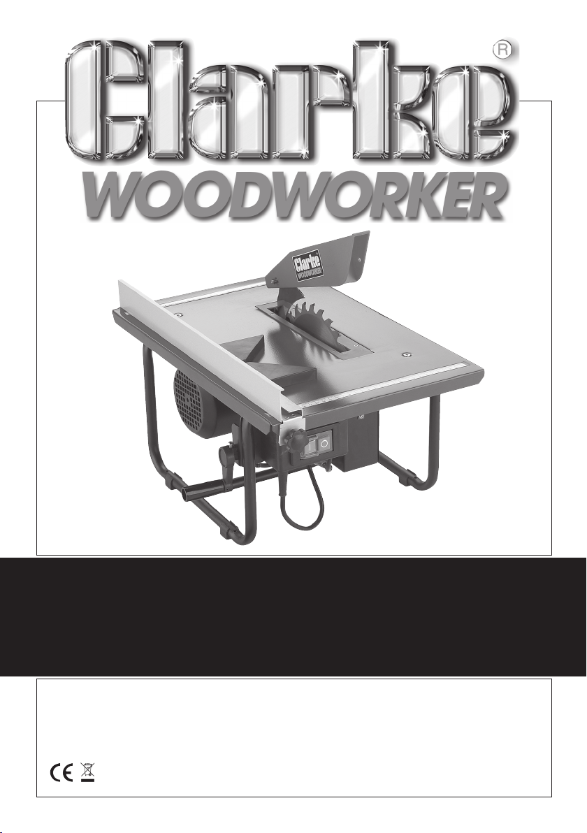
8” (200mm) TABLE SAW
8” (200mm) TABLE SAW
Model: CTS800B
OPERATING & MAINTENANCE
INSTRUCTIONS
© 0606
Page 2
PLEASE READ THIS MANUAL THOROUGHLY
BEFORE USE.
I
f you have any problems using, or setting up this
machine, please ring the CLARKE helpline...
020 8988 7400
020 8988 7400
• Press 1 for Parts
• Press 2 for Technical Assistance
GUARANTEE
This product is guaranteed against faults in manufacture for 12 months
from purchase date. Please keep your receipt as proof of purchase.
This guarantee is invalid if the product has been found to have been
abused in any way, or not used for the purpose for which it was
intended, or to have been tampered with in any way.
Faulty goods should be returned to their place of purchase, no product
can be returned to us without prior permission. The reason for return must
be clearly stated.
This guarantee does not affect your statutory rights.
DECLARATION OF CONFORMITY
We declare that this product complies with the following standards/directives:
• 89/336/EEC • 98/68/EEC • 73/23/EEC • 98/37/EEC (ANNEX IV) • EN 61029-2-1:2002
CERTIFICATE NO: ....... M802 08 41469 063
ISSUED BY: .................. TUV Rheinland Product Service GmbH,
Zertifzierstelle, Ridlerstr. 65,
D-80335 Munich
Serial/Batch No: ....... See Front Cover
When disposing of this product, ensure it is disposed of according to all local ordinances. It must not
be disposed of with general household waste.
2
Page 3

Thank you for purchasing this CLARKE 8” (200mm) Table Saw, which is designed for
DIY and hobby use, to rip and cross cut wood exclusively, up to maximum thickness
of 40mm. Please read ‘Restrictions Of Use’ below.
Before attempting to operate this machine, please read this instruction manual
thoroughly and follow all directions carefully. By doing so you will ensure the safety
of both yourself and others around you, and at the same time, you may look
forward to long and trouble free service from your Table Saw.
RESTRICTIONS OF USE
This saw is NOT suitable for cutting:
• Timber greater than 40mm.
• Metal, stone, rubber, plastic, bones, etc.
• Logs or round timber.
DO NOT fit any other tool or combination of blades.
DO NOT use as a free standing machine or as a hand held machine.
DO NOT modify the machine or its guards/controls in any way.
DO NOT use with any covers/guards removed.
CONTENTS Page
Safety Precautions ........................................................................ 4
Electrical Connections ................................................................. 6
Pre-Assembly Check ..................................................................... 7
Mounting your Table Saw............................................................. 8
The Rip Fence ................................................................................ 8
Dust Extraction ............................................................................... 9
Operating Instructions .................................................................. 9
Rip Sawing ..................................................................................... 9
Cross Cutting ............................................................................... 10
Bevel Cutting ............................................................................... 11
Maintenance............................................................................... 11
Replacing the saw blade........................................................... 12
Specifications .............................................................................. 13
Spare Parts & Servicing ............................................................... 13
Parts List & Diagrams .............................................................. 14-15
3
Page 4
SAFETY PRECAUTIONS
As with all machinery, there are certain hazards involved with their
operation and use. Exercising respect and caution will considerably
lessen the risk of personal injury. However, if normal safety precautions
are overlooked or ignored, personal injury to the operator or damage to
property may result.
1. KNOW YOUR MACHINE. Read this manual carefully. Learn the machines’ applications
and limitations, as well as the specific potential hazards peculiar to it.
2. KEEP GUARDS IN PLACE and in working order.
3. ENSURE THE MACHINE IS EARTHED: The machine is equipped with three-pin
plug which should be plugged into a three-hole electrical socket. Never
remove the earth pin.
4. REMOVE ADJUSTING KEYS AND SPANNERS. Form habit of checking to see that
keys and spanners etc., are removed from the machine before turning it ON.
5. KEEP WORK AREA CLEAN. Cluttered areas and benches invite accidents.
6. DON’T USE IN DANGEROUS ENVIRONMENT. Don’t use power tools or machines
in damp or wet locations, or expose them to rain. Keep work area well lit.
7. KEEP CHILDREN AND VISITORS AWAY. All children and visitors should be kept a
safe distance from work area.
8. MAKE WORKSHOP CHILDPROOF - with padlocks, master switches or by
removing starter keys.
9. DON’T FORCE THE MACHINE. It will do the job better and safer at the rate for
which it was designed.
10. WEAR PROPER APPAREL. Loose clothing, gloves, neckties, rings, bracelets, or
other jewellery may get caught in moving parts. Nonslip footwear is
recommended. Wear protective hair covering to contain long hair.
11. USE SAFETY GLASSES. Also use face or dust mask if cutting operation is dusty.
Everyday eyeglasses only have impact resistant lenses, they are NOT safety glasses.
12. USE EAR DEFENDERS.
13. DON’T OVERREACH. Keep proper footing and balance at all times.
14. MAINTAIN TOOLS IN TOP CONDITION. Keep tools sharp and clean for best
and safest performance. Follow instructions for lubricating and changing
accessories.
15. DISCONNECT TOOLS/MACHINES from electrical supply before servicing and
when changing accessories such as blades, bits, cutters, etc.
16. USE RECOMMENDED ACCESSORIES. Consult the manual for recommended
accessories. The use of improper accessories could be hazardous.
17. NEVER STAND ON TOOL. Serious injury could occur if the tool is tipped or if the
cutting tool is accidentally contacted.
4
Page 5

18. BEFORE USING THE MACHINE, check for damage. If a guard, or other part is found to
be damaged, it should be carefully checked to ensure that it will operate properly
and perform its intended function. Check for alignment, binding, or breakage of
parts, mountings, and any other conditions that may affect its operation. A guard or
any other part that is found to be damaged should be properly repaired or replaced.
20. NEVER LEAVE MACHINE RUNNING UNATTENDED. TURN POWER OFF. Don’t leave
machine until it comes to a complete stop.
21. DRUGS, ALCOHOL, MEDICATION. Do not operate tool whilst under the
influence of drugs, alcohol or any medication.
22. MAKE SURE THE MACHINE IS DISCONNECTED FROM POWER SUPPLY while motor
is being mounted, connected or reconnected.
23. ALWAYS use saw Blade Guard and Riving Knife for every operation.
24. ALWAYS hold the work firmly against the Rip Fence when ripping.
25. ALWAYS USE PUSH-STICK when required. Always use a push-stick for ripping
narrow stock. (Refer to Rip Sawing page 9)
26. NEVER Rip Saw ‘freehand’, which means using your hands to support or guide
the work piece. Always use the Rip Fence to position and guide the work.
27. NEVER stand or have any part of your body in line with the path of the saw blade.
28. NEVER reach behind or over the cutting tool for any reason.
29. ALWAYS remove the Rip Fence when cross cutting, unless using the angle guide.
30. NEVER use the Rip Fence as a cut-off when cross cutting.
31. NEVER attempt to free a stalled saw blade without first turning the saw OFF.
Switch off and disconnect from power supply immediately to prevent motor damage.
32. PROVIDE adequate support to the rear and sides of the saw table for wide or
long workpieces.
33. AVOID KICKBACKS (work thrown back towards you) by:
a. keeping the blade sharp,
b. keeping the Rip Fence in line with the saw blade,
c. keeping the Riving Knife and Blade Guard in place,
d. by not releasing the work before it is pushed all the way past the saw blade,
e. by not ripping work that is twisted or warped or does nor have a straight
edge to guide along the fence.
34. AVOID awkward operations and hand positions where a sudden slip could
cause your hand to move into the saw blade.
35. NEVER use solvents to clean plastic parts. Solvents could possibly dissolve or
otherwise damage the material. Only a soft dry cloth should be used to
clean plastic parts.
36. BOLT the saw to a supporting surface (table, bench or mounting board, as
appropriate)
37. ALWAYS ensure the Riving Knife is directly in line with the Saw Blade at all times
38. DO NOT exceed the Duty Cycle for the machine. (see Specifications).
5
Page 6
ELECTRICAL CONNECTIONS
Connect the mains lead to a standard 230 volt (50Hz) electrical supply via a 13
amp BS1363 plug fitted with a 5 amp fuse.
WARNING: THIS APPLIANCE MUST BE EARTHED.
IMPORTANT: The wires in the mains lead are coloured in accordance with the
following code:
Green & Yellow - Earth
Blue - Neutral
Brown - Live
As the colours of the flexible cord of this appliance may not correspond with the
coloured markings identifying terminals in your plug, proceed as follows:
• Connect GREEN & YELLOW cord to terminal marked with a letter ”E” or Earth
symbol " ", or coloured GREEN or GREEN & YELLOW.
• Connect BROWN cord to terminal marked letter “L” or coloured RED.
• Connect BLUE cord to plug marked letter “N” or coloured BLACK.
FUSE RATING
The fuse for the plug in this appliance must be rated at 5 amps.
We recommend that this machine is connected to the mains supply via a Residual
Current Device (RCD).
EXTENSION CABLES
If an extension cable is used always ensure that it is fully unwound. The maximum
extension length is 25M, and the wire size in the cables must be at least 1.5mm in
diameter. As a general rule the extension cable must be thicker than the cable
supplied with the Table Saw. If longer extensions are required please seek advice
from a qualified electrician.
IF IN DOUBT CONSULT A QUALIFIED ELECTRICIAN.
DO NOT ATTEMPT ANY ELECTRICAL REPAIRS YOURSELF.
6
Page 7
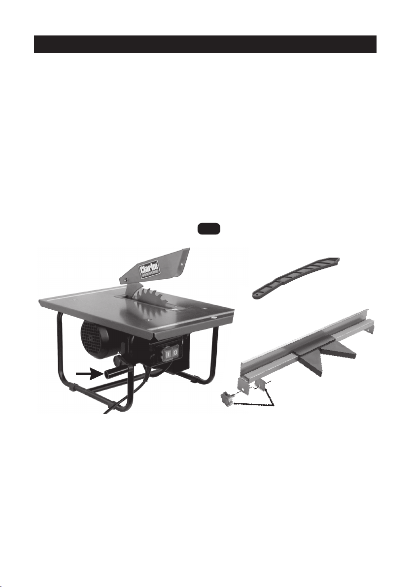
PRE-ASSEMBLY CHECK
Unpack your Table Saw and lay out the various components, checking to ensure
that all parts detailed below have been supplied. Should any of the components
be missing or damaged then please contact your dealer immediately.
A Table Saw with fitted plug 1
B Rip Fence assembly 1
C Push Stick 1
D45O Cross Cut Guide 1
E Crank Handle C/w Screw 1
F Knob Headed Screws with clamp 2
(For use with Ripfence)
Fig.1
A
C
B
D
E
F
Some minor assembly work is required, as follows:
1. Attach the handle, arrowed in the illustration above, using the screw to secure.
2. The Rip Fence. Simply insert the knob headed screws through the holes in the
end of the fence and screw on the clamp plates.
BEFORE USE, the Table Saw MUST be bolted firmly to either a workbench or a piece
of sturdy plywood, and this must then be firmly clamped to a workbench before
use. See Mounting the Saw.
7
Page 8
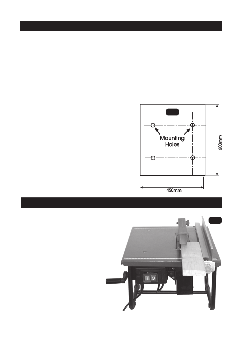
MOUNTING THE SAW
If the Saw is to be bolted to a workbench, you should ensure that it is positioned in
the most convenient location. Ensure adequate lighting is available and the
electrical supply is close at hand.
A mounting board should be used if a permanent mounting is unavailable or not
desired. The board is necessary in order to give the saw stability during operation.
It is recommended that the board dimensions are not less that 450x600mm and at
least 15mm thick.
Once mounted, as described below, the board must be securely clamped to a
workbench, using at least two ‘G’ clamps, one at each side, and a constant check
made to ensure they are tight during operation.
To mount the saw, drill four 8mm holes, using
the machine as a template to mark out the
position of the holes, and bolt the machine
down with 5mm bolts, ensuring flat washers are
used between the bolt head and base.
If a mounting board is used, countersunk head
screws should be used, with the holes in the
underside of the board countersunk to suit. The
mounting holes should be centrally located on
the board.
It is important to ensure the nuts are not overtightened, and are tightened progressively to
avoid distorting the base.
Fig.2
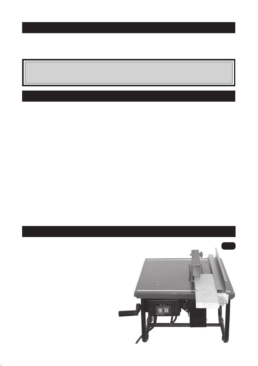
RIP FENCE
Your Table Saw is provided with a Rip Fence
which is essential to ensure straight line cutting,
and should ALWAYS be used when rip sawing.
The Fence is secured to the table with two
knob head screws, acting on a pair of
clamp plates, one at the front and one
at the rear of the table.
The fence may be placed at any suitable
position on the table, and either left
or right of the saw blade. Do not
over-tighten the securing knobs.
Measurement scales are provided
at the front and back of the table. These
may be used to position the rip fence for
rough cutting. If precision is required, use a
ruler between the rip fence and the front
and back of the blade.
8
Fig.3
Rip Fence is shown in its Lower Position
Page 9
DUST EXTRACTION
This table saw is equipped with a dust extraction port at the rear of the machine.
For safe operation, we recommend that a suitable dust extraction device or
vacuum cleaner is connected during operation.
WARNING:
Excessive sawdust build up around the motor could possibly ignite and
cause damage to either the motor, table saw or your workshop.
OPERATION
Before use, ALWAYS check:
• To ensure ALL parts are sound and properly fixed. (Any broken or damaged
part must be replaced before machine is used).
• Supply voltage is compatible with machine i.e. 230V, A.C. 50Hz.
• To ensure the machine is properly mounted (see Mounting the Saw).
• To ensure the blade rotates freely.
• To ensure the Riving Knife is directly in line with the saw blade (See p12).
• To ensure the Blade Guard falls completely to the table under its own weight.
• To ensure you comply with all safety precautions (see pages 3 -5),
When perfectly satisfied switch ON by pressing the switch ‘I’, at the front of the
machine. Switch OFF by pressing ‘O’.
NOTE: ON/OFF switch is a ‘no volt release’ type, i.e. if the power fails or is
disconnected while the machine is in use, the machine will not restart when power
is restored.....the ‘I’ (ON ) button must be pressed.
RIP SAWING
Rip Sawing is the term used to describe a cut which is in the
same direction as the grain of the wood.
For this operation the Rip Fence should always
be used.
To Rip Cut a piece of wood you should
proceed as follows:
1. Adjust the Rip Fence to required width of
cut. - the distance between the edge of
the blade and the Rip Fence, ensuring it
is perfectly parallel to he saw blade.
Use the measurement scales at the
front and back of the table for rough
cutting or measure the distance between
the front and back of the blade to the rip
fence with a rule for precision.
9
Fig.4
Page 10
NOTE: The Rip fence can be mounted left or right hand side of blade.
2. Hold workpiece against the Rip Fence and feed through blade. Do not force it.
If the motor slows, feed more slowly. NEVER hold on to offcut of the wood.
3. If sawing long lengths of material, arrange a support at the rear of the
machine, or use an assistant to support the material as it runs off.
4.
IMPORTANT! 1. Always use the push stick to push the workpiece past the saw blade.
2.. DO NOT exceed the Duty Cycle..see ‘Specifications’
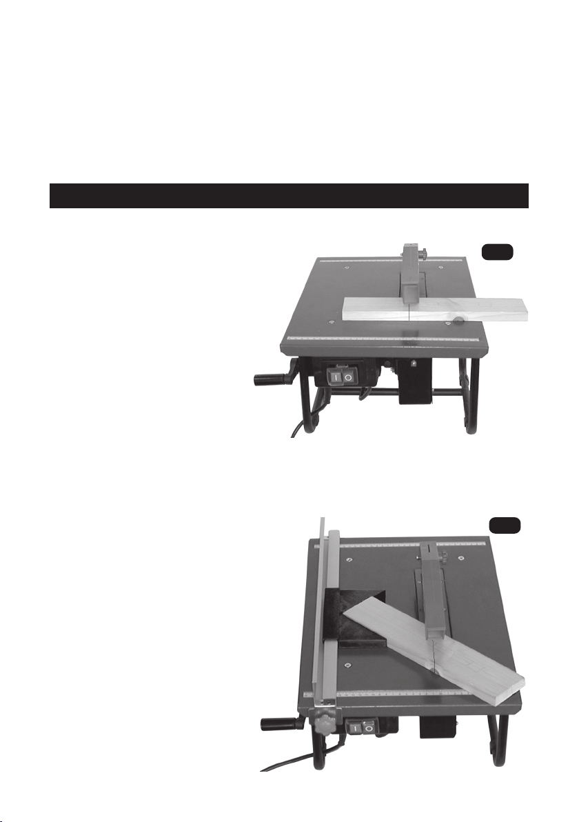
CROSS CUTTING
Cross Cutting is the term used to describe a cut which is across the grain of the wood.
This operation is carried out as follows:
1. Remove the Rip Fence.
2. Slacken the Blade securing knobs,
front and rear. (These are shown
more clearly Fig.7 on p.11)
3. Turn the Adjuster handle so that
the blade is at 90O, as indicated by
the pointer, then tighten the
securing knobs.
NOTE: If a precision 90O cut is
required, check the angle of the saw
blade using a square, make any
adjustments necessary using the adjuster
handle, then reset the pointer.
Fig.5
4. Clearly mark the workpiece where the cut is required.
5. Hold workpiece firmly and feed through saw blade, ensuring feed is straight
(DO NOT attempt to cut curves).
6. If sawing long sections arrange supports
Fig.6
at one or both sides of machine, as
required.
O
Cross cuts at 45
may also be cut
using the Special guide provided.
Attach the Rip Fence, and locate
the guide in the slot provided, as
shown in Fig.6.
Hold the work firmly in the guide, and
proceed to feed the work into the
blade, ensuring you do not restrain or
hold on to the offcut.
IMPORTANT: The Ripfence may ONLY
be used for cross cutting in
conjunction with the angle gauge.
10
Page 11
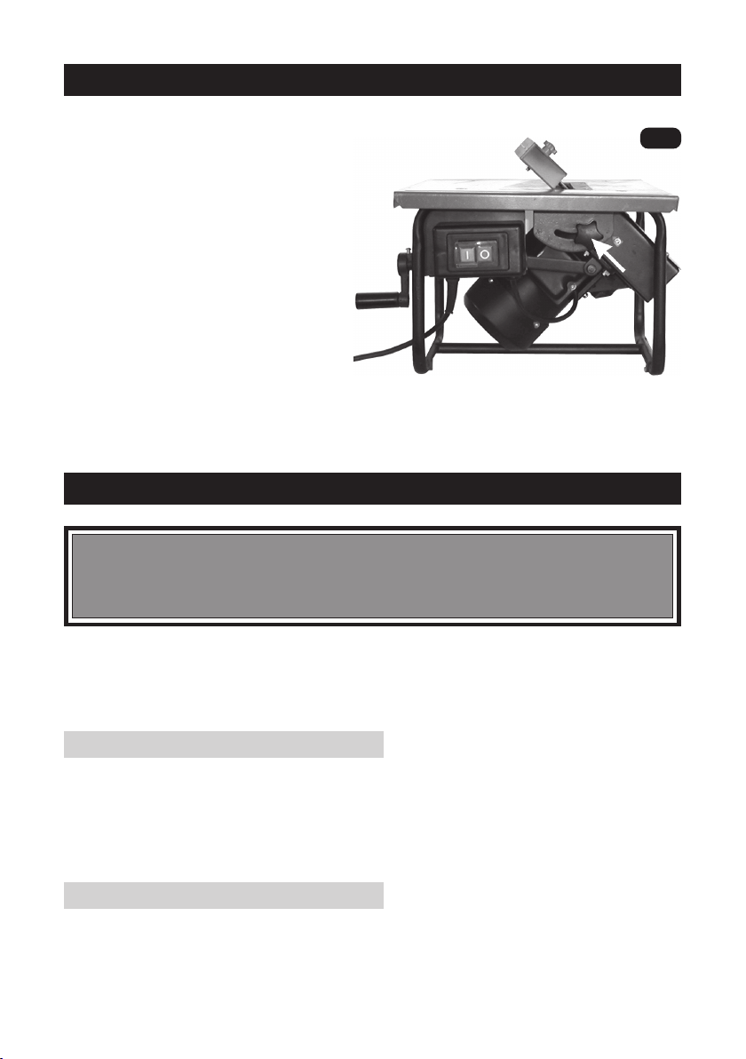
BEVEL CUTTING
Rip and cross cuts can be made at
angles between 0o - 45o.
1. Slacken the Blade securing
knobs, front and rear (Front knob
is arrowed in Fig.7).
2. Turn the Adjuster handle as
required to the desired angle as
indicated on the scale.
3. Tighten both securing knobs.
4. Proceed to cut as for rip or
cross cutting.
Note: If precision is required, use a
protractor between the blade and
table.
MAINTENANCE
WARNING!
Ensure the machine is disconnected from the mains supply BEFORE any
maintenance tasks or adjustments are carried out.
Fig.7
Your Table Saw requires very little maintenance.
Carrying out those tasks specified below, will not only ensure the maximum safety of
operation, but will also prolong the life of your machine.
AFTER EACH USE:
Saw dust must be removed from the machine.
Remove the side cover by unscrewing the five securing screws, and use a vacuum
cleaner to ensure all dust is removed, before replacing the cover.
All plastic components can be wiped clean with a soft dry cloth.
KEEP SAW BLADE SHARP.
Use a half round file where necessary to keep the teeth sharp. A blade that is
badly dulled or with broken or badly damaged teeth should be replaced
immediately.
11
Page 12
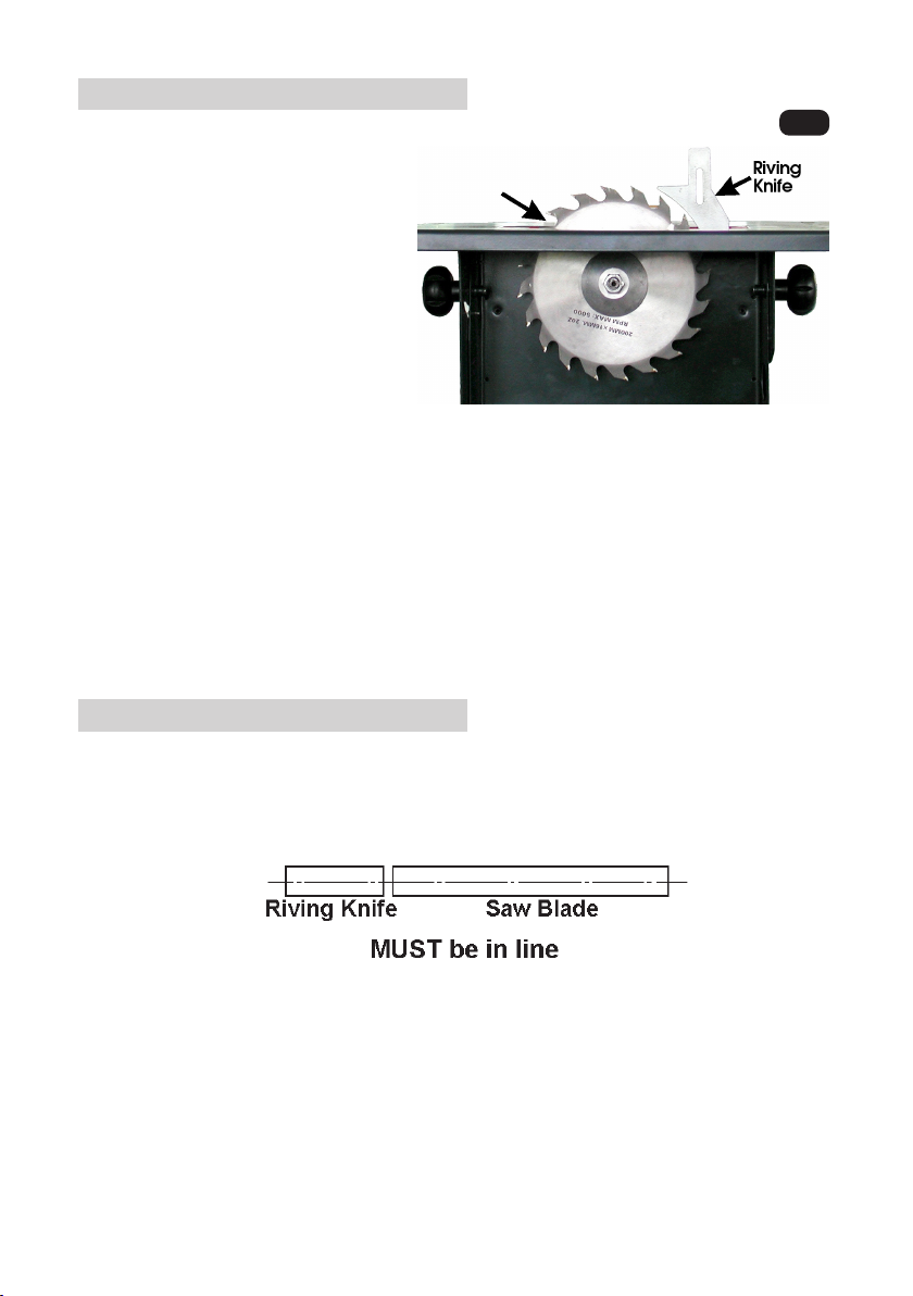
REPLACING THE SAW BLADE
Fig.8
1. Remove the side cover by
unscrewing the five securing
screws.
2. Place a steel bar or
screwdriver blade between
the table top and one of the
saw blade teeth, (at the point
arrowed in Fig.8), then undo
the saw blade securing nut normal right hand thread.
3. Remove the outer flange
followed by the saw blade by
angling it outwards at the bottom so that it is clear of the motor shaft, and
carefully withdrawing it from below.
4. Replace in reverse order ensuring the saw blade teeth face downwards at
the front of the table.
Hold the blade firmly whilst wearing a good industrial glove when tightening
the centre nut, taking care to avoid damaging your hand on the sharp
teeth.
RIVING KNIFE
The riving knife is an important component and must always be in place
and directly in line with the saw blade. It prevents the work from chattering
as it passes through the blade.
If necessary, remove the Table Insert, then slacken the two securing screws
and adjust accordingly, ensuring the clearance between the saw blade
and riving knife is 5mm maximum. Inspect at regular intervals to ensure
the gap is correctly maintained, and adjust as required.
It may also be necessary to remove the Riving Knife and bend back into
shape if it is not exactly in line with the saw blade.
12
Page 13

SPECIFICATIONS
Model No. ................................................................ CTS800B
Part No. ..................................................................... 6500723
Motor ........................................................................ 230V 50Hz 1ph
Power Rating ............................................................ 600Watts
Motor Speed (No Load).......................................... 2950RPM
Blade Size ................................................................. 200mm, 16mm Bore
Depth of cut at 90 degrees .................................... 40mm
Depth of cut at 45 degrees .................................... 25mm
Table size.................................................................. 500 x 335mm
Dust Port ................................................................... 40mm O.D.
Weight ...................................................................... 12.5kg
Noise Level............................................................... 108dBL
(Sound Power Level) (Cutting 25mm soft wood)
Duty Cycle ............................................................... S3 30%**
** This denotes that this machine may be used for 3 minutes only, in any 10 minute period.
Please note that CLARKE International reserves the right to modify design at any time without prior notice.
Any significant change will be reflected in this manual.
WA
SPARE PARTS AND SERVICE
REPLACEMENT BLADES
Replacement blades for your CTS800 Table Saw are available from your local
dealer as follows:
24 Tooth TCT Blade .............. Model: TCT200 ................ Part No. 490070
For Spare Parts and Service, please contact your nearest dealer, or CLARKE
International, on one of the following numbers.
PARTS & SERVICE TEL: 020 8988 7400
PARTS & SERVICE TEL: 020 8988 7400
or e-mail as follows:
or e-mail as follows:
PARTS: [email protected]
PARTS: [email protected]
SERVICE: [email protected]
SERVICE: [email protected]
13
Page 14
PARTS LIST
No. Description Part No.
1 Foot Support GRCTS800B01
2 Frame GRCTS800B02
3 Screw GRCTS800B03
4 Spring Washer GRCTS800B04
5 Washer GRCTS800B05
6 Motor Support GRCTS800B06
7 Motor GRCTS800B07
8 Lower Blade Guard GRCTS800B08
9 Dust Outlet GRCTS800B09
10 Plastic Housing GRCTS800B10
11 Conn. Rod Bracket GRCTS800B11
12 Screw GRCTS800B12
13 Washer GRCTS800B13
14 Nut GRCTS800B14
15 Table GRCTS800B15
16 Big Washer GRCTS800B16
17 Lock Knob GRCTS800B17
18 Pin GRCTS800B18
19 Screw GRCTS800B19
20 Screw GRCTS800B20
21 Star Washer GRCTS800B21
22 Riving Knife GRCTS800B22
23 Plate GRCTS800B23
24 Inner Flange GRCTS800B24
25 Saw Blade See Page 13
26 Outer Flange GRCTS800B26
27 Centre Nut GRCTS800B27
28 Side Cover GRCTS800B28
29 Washer GRCTS800B29
30 Screw GRCTS800B30
No. Description Part No.
31 Handle GRCTS800B31
32 Screw GRCTS800B32
33 Sleeve GRCTS800B33
34 Shaft GRCTS800B34
35 Box GRCTS800B35
36 Screw GRCTS800B36
37 Nut GRCTS800B37
38 Washer GRCTS800B38
39 Connecting Rod GRCTS800B39
40 Washer GRCTS800B40
41 Pin GRCTS800B41
42 Locking Pin GRCTS800B42
43 Screw GRCTS800B43
44 Switch Box GRCTS800B44
45 Switch GRCTS800B45
46 Cable Protector GRCTS800B46
47 Cable GRCTS800B47
48 Clable Gland GRCTS800B48
49 Table Insert GRCTS800B49
50 Screw GRCTS800B50
51 Blade Guard GRCTS800B51
52 Locking Knob GRCTS800B52
53 Washer GRCTS800B53
54 Ruler Label GRCTS800B54
55 Rip Fence GRCTS800B55
56 Locking Knob GRCTS800B56
57 Locking Clamp GRCTS800B57
58 Pointer GRCTS800B58
59 Cross Cut Guide GRCTS800B59
60 Push Rod GRCTS800B60
14
Page 15
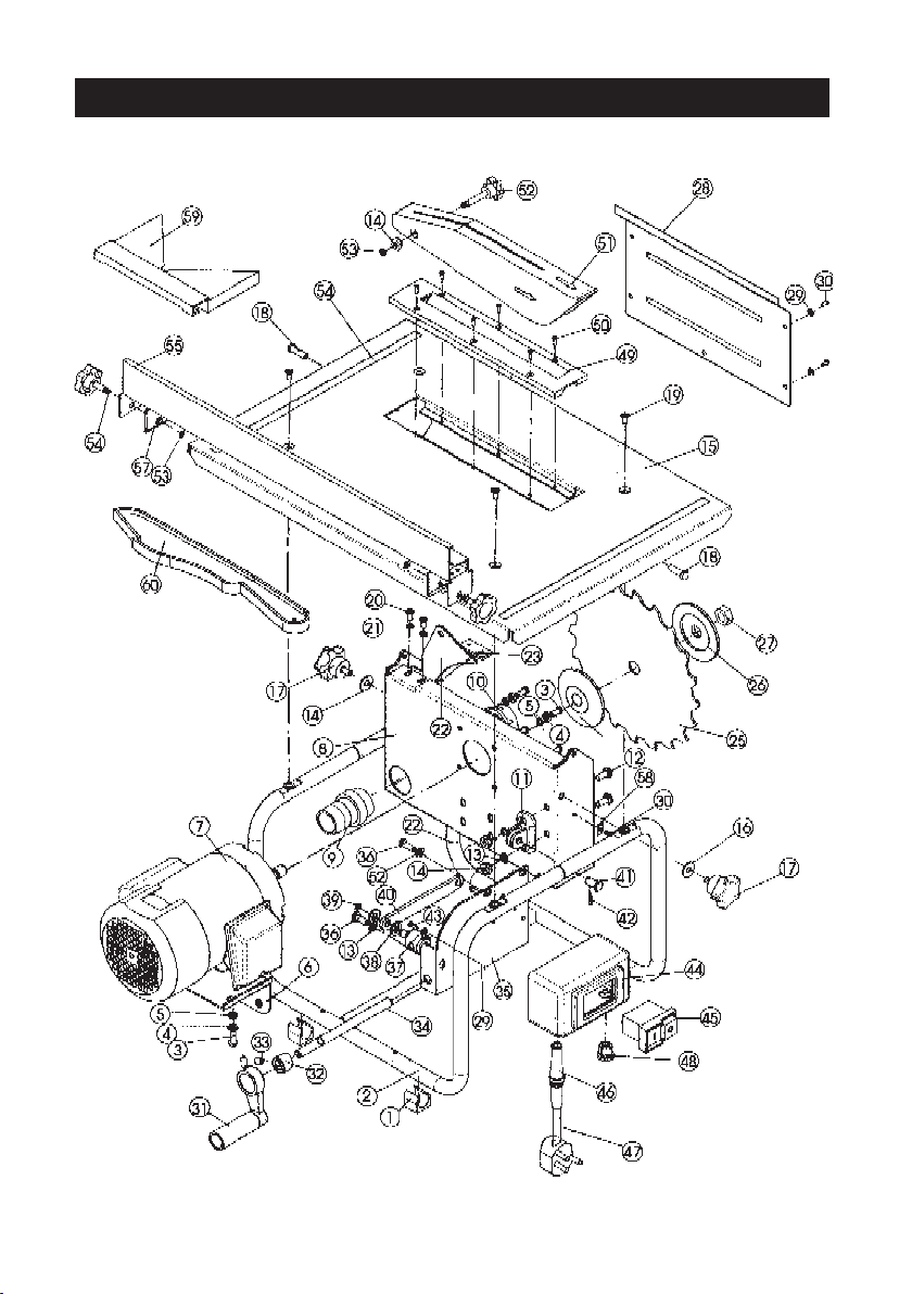
PARTS DIAGRAM
15
 Loading...