

Page 1

WOODLATHE
WOODLATHE
MODEL NO. CWL-20RV
Part No. 6500670
OPERATING & MAINTENANCE
INSTRUCTIONS
1202
Page 2

SPECIFICATIONS
Motor ................................................................ 230V 50Hz 1 Phase
½ HP Induction
Current rating .................................................. 2.2 amp
Max distance between centres ................... 850mm (35.4")
Centre height turning capacity .................... 304mm (12") Diameter
Gross weight ................................................... 85kg
Dimensions ...................................................... 1380x320x362mm
Drill chuck speeds (RPM)** ............................ 1. 500 RPM 6. 1210 RPM
2. 620 RPM 7. 1400 RPM
3. 760 RPM 8. 1590 RPM
4. 900 RPM 9. 1790 RPM
5. 1050 RPM 10. 2000 RPM
**The Speeds quoted are correct to within a 15% tolerance.
2
19
Page 3

Thank you for purchasing your CLARKE, Variable Speed, Reversible Head, Wood
Lathe.
Before attempting to operate this machine, please read this instruction manual
thoroughly, and follow all directions carefully. By doing so you will ensure the safety
of both yourself andthat of others around you, and at the same time, you should
look forward to long and trouble free service from your Wood lathe.
GUARANTEE
This product is guaranteed against faults in manufacture for 12 months
from date of purchase. Please keep your receipt as proof of purchase.
This guarantee is invalid if the product has been found to have been
abused or tampered with in any way, or not used for the purpose for which
it was intended. The reason for return must be clearly stated.
This guarantee does not affect your statutory rights.
TABLE OF CONTENTS PAGE
General Safety Precautions ...................................................................... 4
Additional Safety Rules for Wood Lathes ................................................ 5
Electrical Connections .............................................................................. 7
Assembly ..................................................................................................... 8
Preparation for Use .................................................................................. 10
Speed Selection ....................................................................................... 13
Starting Procedure ................................................................................... 14
Maintenance ............................................................................................ 14
Parts List and Diagram ....................................................................... 16-17
Specifications ........................................................................................... 19
18
3
Page 4
GENERAL SAFETY RULES FOR OPERATING MACHINERY
WARNING
As with all machinery, there are certain hazards involved with their
operation and use. Exercising respect and caution will considerably lessen
the risk of personal injury. However, if normal safety precautions are
overlooked, or ignored, personal injury to the operator may result.
• KNOW YOUR MACHINE. Read the manual carefully. Learn the machines
applications and limitations, as well as the specific potential hazards peculiar to it.
• KEEP GUARDS IN PLACE and in working order.
• EARTH ALL MACHINES. If the machine is equipped with three-pin plug, it should
be plugged into a three-pin electrical socket. Never remove the earth pin.
• REMOVE ADJUSTING KEYS AND WRENCHES.
• KEEP WORK AREA CLEAN. Cluttered areas and benches invite accidents.
• DON’T USE IN DANGEROUS ENVIRONMENT. Don’t use machinery in damp or
wet locations, or expose them to rain. Keep work area well lit.
• KEEP CHILDREN AND VISITORS AWAY. All children and visitors should be kept a
safe distance from work area.
• MAKE WORKSHOP CHILDPROOF - with padlocks, master switches or by
removing starter keys.
• DON’T FORCE THE MACHINE. It will do the job better and safer, at the rate for
which it was designed.
• USE RIGHT TOOL. Don’t force a tool or attachment to do a job for which it was
not designed.
• WEAR PROPER APPAREL. Loose clothing, gloves, neckties, rings, bracelets, or
other jewellery may get caught in moving parts. Nonslip footwear is
recommended. Long hair should be contained.
• USE SAFETY GLASSES. Also use face or dust mask if cutting operation is dusty.
Everyday eyeglasses only have impact resistant lenses, they are NOT safety
glasses.
• USE EAR DEFENDERS.
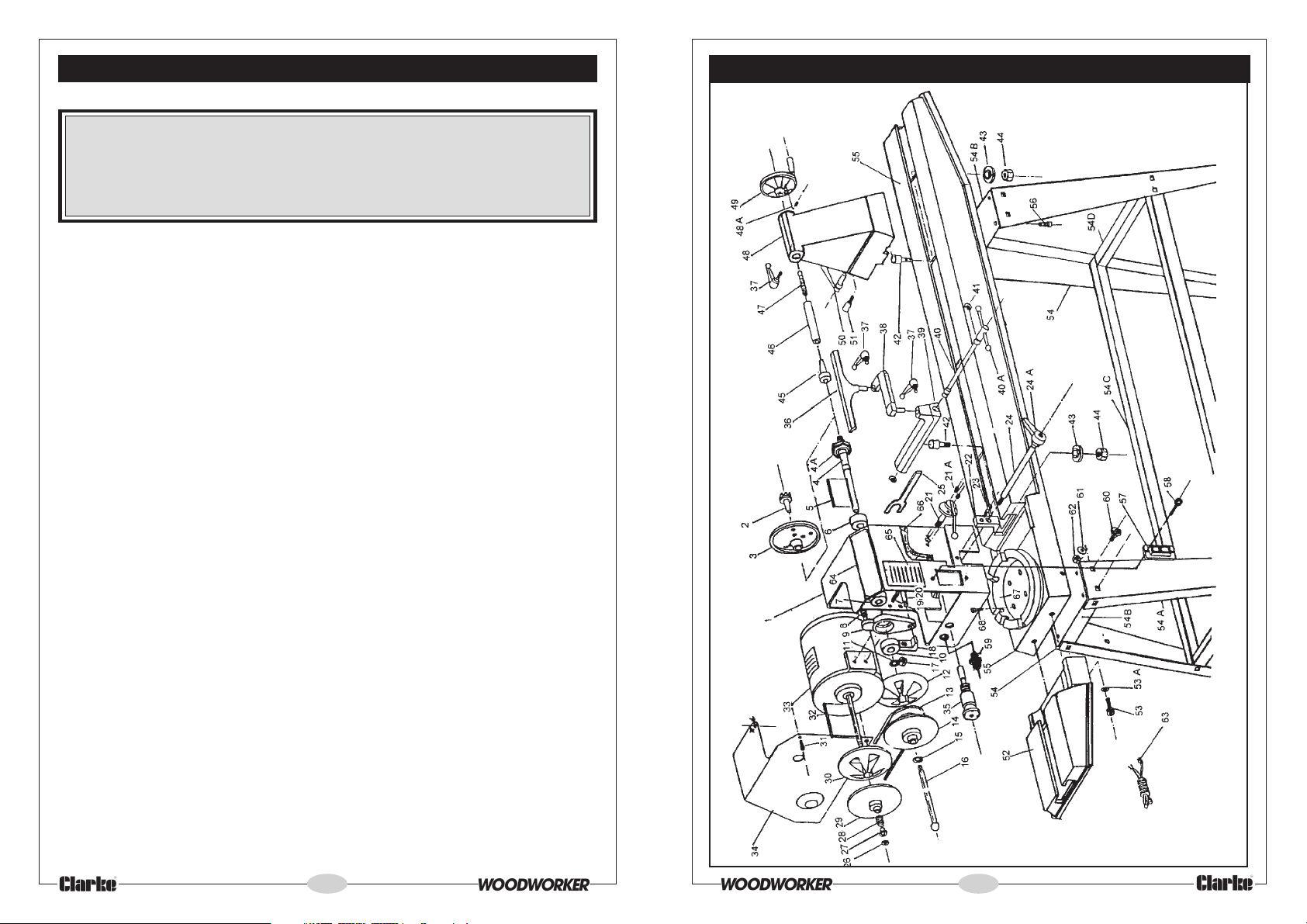
PARTS DIAGRAM
• DON’T OVERREACH. Keep proper footing and balance at all times.
• MAINTAIN TOOLS IN TOP CONDITION. Keep tools sharp and clean for best and
safest performance. Follow instructions for lubricating and changing
accessories.
4
17
Page 5

PARTS LIST
No. Description Part No. No. Description Part No.
Headstock
1
Live Centre
2
Face Plate
3
Drive Spindle
4
Spindle Collar
4A
Key (4x4x85mm)
5
Bearing (6205ZZ)
6
Bearing (6205ZZ)
7
Spring
8
Bracket Shift Lever
9
Ball Bearing (6006Z)
10
Circlip
11
Pulley Spindle (Right)
12
V-Belt 23mm
13
Pulley Spindle (Left)
14
Circlip
15
Tommy Bar
16
Lock Nut 12mm
17
Clamp Left
18
Hex Screw 8x20mm
19
Rack
20
Gear Assembly
21
Hex Socket Screw
21A
Clamp Right
22
Hex Screw
23
Clamp Spindle
24
Headstock Clamp Handle
24A
Hex. Wrench
25
Circlip
26
Sleeve
27
Spring
28
Pulley Motor (Right)
29
Pulley Motor (Left)
30
Pan Head Screw 5x10mm
31
Key 4x4x85mm
32
Motor
33
Cover Motor
34
Headstock Lock Assy
35
Tool Rest
36
SD2001RV
SD2002RV
SD2003RV
SD2004RV
SD2004ARV
SD2005RV
SD2006RV
SD2007RV
SD2008RV
SD2009RV
SD2010RV
SD2011RV
SD2012RV
SD2013RV
SD2014RV
SD2015RV
SD2016RV
SD2017RV
SD2018RV
SD2019RV
SD2020RV
SD2021RV
SD2021ARV
SD2022RV
SD2023RV
SD2024RV
SD2024ARV
SD2025RV
SD2026RV
SD2027RV
SD2028RV
SD2029RV
SD2030RV
SD2031RV
SD2032RV
SD2033RV
SD2034RV
SD2035RV
SD2036RV
37
Handle Assy
38
Tool Rest Extension
39
Tool Rest Body
40
Tool Rest Clamp Rod
40A
Tool Rest Clamp Handle
41
Circlip
42
Bolt
43
Clamp
44
Hex Nut 18mm
45
Centre
46
Tailstock Spindle
47
Tailstock Screw
48
Tailstock
48A
Set Screw
49
Handle
50
Locking Handle - Tailstock
51
Bolt
52
Extension Bed
53
Screw 10x25mm
53A
Spring washer
54
Stand Assembly
54A
Stand Leg
54B
Bed Mounting Plate
54C
Stand Long Cross Member
54D
Stand Short Cross Member
55
Lathe Bed
56
Screw 8x16mm
57
Switch
58
Screw 4x16mm
59
Plastic Jam nut
60
Carriage Bolt
61
Washer
62
Nut 8x18 NC
63
Power cable
64
Label
65
Warning Label
66
Speeds Label
67
Headstock Mounting Ring
68
Mounting Ring Allen Screw
SD2037RV
SD2038RV
SD2039RV
SD2040RV
SD2040ARV
SD2041RV
SD2042RV
SD2043RV
SD2044RV
SD2045RV
SD2046RV
SD2047RV
SD2048RV
SD2048ARV
SD2049RV
SD2050RV
SD2051RV
SD2052RV
SD2053RV
SD2053ARV
SD2054RV
SD2054ARV
SD2054BRV
SD2054CRV
SD2054DRV
SD2055RV
SD2056RV
SD2057RV
SD2058RV
SD2059RV
SD2060RV
SD2061RV
SD2062RV
SD2063RV
SD2064RV
SD2065RV
SD2066RV
SD2067RV
SD2068RV
• ALWAYS DISCONNECT THE MACHINE before servicing or changing
accessories.
• AVOID ACCIDENTAL STARTING. Ensure the machine is switched OFF before
plugging in.
• CHECK FOR DAMAGE. If part of the machine (eg. A cover or guard), is
damaged, it should be carefully inspected to ensure it can perform its’
intended function correctly. If in doubt the part should be renewed. Damage
to moving parts or major components should be Inspected by a qualified
technician before operating the machine. Contact your local dealer for
advice.
• DO NOT STAND ON THE MACHINE. Serious injury could occur if the machine is
tipped over. Do not store materials above or near the machine such that it is
necessary to stand on the machine to get to them.
• NEVER operate a machine when under the influence of alcohol, drugs or
medication.
ADDITIONAL SAFETY RULES FOR WOOD LATHES
WARNING:
THIS MACHINE MUST NOT BE MODIFIED, OR USED FOR ANY PURPOSE OTHER
THAN THAT FOR WHICH IT IS DESIGNED.
• IMPORTANT: You should not operate this machine unless you are thoroughly
familiar with wood turning lathes and wood turning techniques. If there is any
doubt whatsoever, you should consult a qualified person.
• Do not operate the machine until it is completely assembled, and this entire
manual, has been read and understood.
• Ensure the proper electrical regulations are followed, and that the machine is
properly earthed.
• Before switching the machine ON, ALWAYS:-
a. Clear the lathe bed of ALL objects (tools, scraps of wood etc.)
b. Examine the setup carefully, ensuring nothing could possibly interfere with
the rotating workpiece. eg. The tool rest is secure and not liable to swing
into the workpiece. Rotate the workpiece by hand to check clearance.
c. Ensure the tool rest is adjusted to the correct height, and is as close to the
workpiece as possible.
d. Ensure all clamps are properly secured.
e. Your clothing is properly adjusted.
f. Ensure the workpiece is centralised
16
5
Page 6

• Make all adjustments with the power OFF.
• ALWAYS use the slowest speed when starting a new workpiece, and cut at
correct speed for material and shape.
• ALWAYS remove the tool rest when sanding or polishing.
• When turning between centres, always ensure that the tailstock centre is snug
against the workpiece, with the spindle locked, AND the Tailstock securely
locked to the bed. NEVER loosen the tailstock spindle OR the tailstock with the
workpiece turning.
NOTE: The centre should be lubricated (unless it is a ball bearing type). Refer to
your wood turning manual.
• DO NOT drive the workpiece into the live centre when the centre is installed
in the headstock. Always set the workpiece into the centre with a soft mallet
first and then mount the Centre (with workpiece attached), to headstock
spindle.
• When using the Faceplate, ensure the workpiece is securely fastened to it,
and that the appropriate size faceplate is used to correctly support the
workpiece. Ensure also that the securing screws cannot interfere with the
turning tool at the finished dimension.
• ALWAYS rough cut the workpiece as close as possible to the finished shape,
before mounting on to a faceplate.
• ALWAYS examine the workpiece for flaws. Do not use wood which is split, or
has knots. Test glued joints before mounting on to lathe, to ensure they have
completely set.
• When roughing off, DO NOT jam tool into workpiece, or take too big a cut.
• ALWAYS clean the machine at the end of a working session. Remove centres
from the headstock AND tailstock and store them. Ensure the work area is
cleaned before leaving the machine.
• Should any part of the lathe be missing, damaged, or fail in any way, or any
electrical component fail to perform properly, shut OFF the machine, and
disconnect from the power supply. Replace missing, damaged or failed parts
before resuming operation. If in doubt, consult your local dealer. Always
disconnect from the power supply when carrying our repairs.
• Be particularly careful with your clothing when operating a lathe. Always
wear safety glasses, and long hair should be contained. See General Safety
Instructions - Apparel.
• Do Not exceed recommended speeds. Refer to chart on page 12.
2. Remove the four screws securing the motor cover (item 34).
3. Slip the belt over the motor pulley, and replace it with a new one.
Note: The drive belt is tensioned automatically. If, after changing the drive
belt, the speeds are still too low, it is an indication that the spring tensioner
(item 28), on the end of the motor shaft, is weak and needs replacing. Consult
your local dealer, or CLARKE International Service Dept. on 0208 988 7400
SPARE PARTS and SERVICING
For Spare Parts and Service, please contact your nearest dealer,
or CLARKE International, on one of the following numbers.
PARTS & SERVICE TEL: 020 8988 7400
PARTS & SERVICE FAX: 020 8558 3622
or e-mail as follows:
PARTS: [email protected]
SERVICE: [email protected]
6
15
Page 7
STARTING PROCEDURE.
ELECTRICAL CONNECTIONS
1. Having prepared the lathe in accordance with the instructions given, ensure
the work is properly centralised, properly held, and is completely secure. Turn
the workpiece by hand to ensure that it moves freely without interference.
2. Remove any wood shavings, and ensure that no loose tools are in the vicinity.
3. Check ALL clamps securing the Headstock, Tool Rest and Tailstock, to ensure
they are firmly clamped.
4. Switch on the machine ensuring it is set to its slowest speed, and then increase
the speed as desired.
NOTE: When you have finished using the machine, always switch OFF having first
selected the lowest speed.
MAINTENANCE
Headstock.
If there is movement of the headstock when the clamp is fully applied, the
Headstock Mounting Ring (item 67), has worked itself loose, probably caused by
the machines’ vibration over a period of time.
To rectify the problem, turn the clamp handle (item 24A) anticlockwise until the
clamp spindle can be completely removed together with the two clamp brackets,
(one adjacent to the clamp handle, mounted on the clamp spindle, and one on the
opposite side of the headstock, beneath the motor, and into which the clamp
spindle is screwed). Be extremely careful not to knock the headstock, as it is now free
to be lifted and removed, to reveal the Mounting Ring (item 67), beneath.
With the Headstock removed, tighten the four Mounting Ring Allen screws (item
68). Re-assemble in reverse order, ensuring the large tapered sections of the
clamp brackets face downwards and are in contact with the underside of the
Headstock Mounting Ring.
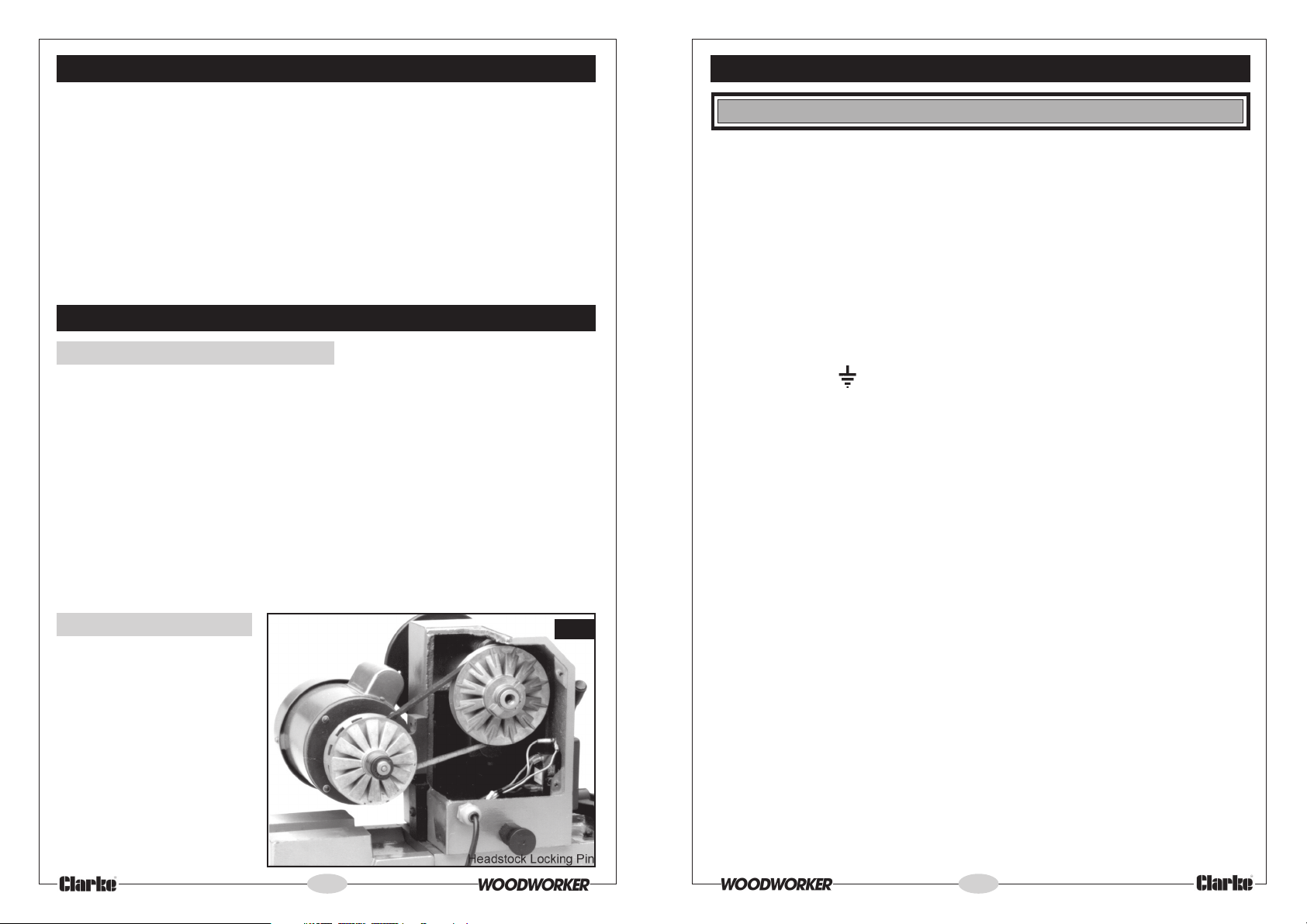
Drive Belt (see fig. 7)
Should the lathe slow down
whilst turning, it is an indication
that the drive belt is stretched
and needs renewing, in
which case, proceed as
follows
1. Set the variable speed
control to its highest
speed. Turn the spindle
by hand to ensure the
speed is fully engaged.
(The drive belt is easier to
remove in this position).
14
Fig. 7
WARNING! THIS APPLIANCE MUST BE EARTHED
IMPORTANT: Connect the mains lead to a standard, 230 Volt (50Hz) electrical
supply through an approved 13 amp BS 1363 plug, or a suitably fused isolator
switch. The wires in the mains lead are coloured in accordance with the following
code:
Green & Yellow - Earth
Blue - Neutral
Brown - Live
As the colours of the flexible cord of this appliance may not correspond with the
coloured markings identifying terminals in your plug proceed as follows:
• Connect GREEN & YELLOW cord to terminal marked with a letter “E” or
Earth symbol “ ” or coloured GREEN or GREEN & YELLOW.
• Connect BROWN cord to terminal marked with a letter “L” or coloured RED
• Connect BLUE cord to terminal marked with a letter “N” or coloured BLACK
We recommend that this machine is connected to the mains supply through a
Residual Current Device.
In the event that this appliance is fitted with a plug which is moulded onto the
electric cable (i.e. non-rewirable) please note:
1. The plug must be thrown away if it is cut from the electric cable. There is a
danger of electric shock if it is subsequently inserted into a socket outlet.
2. Never use the plug without the fuse cover fitted.
3. Should you wish to replace a detachable fuse carrier, ensure that the correct
replacement is used (as indicated by marking or colour code).
4. Replacement fuse covers can be obtained from your local dealer or most
electrical stockists.
5. The fuse in the plug must be replaced with one of the same rating (13 amps)
and this replacement must be approved to BS1362.
If in doubt, consult a qualified electrician. Do not attempt any electrical repairs
yourself.
7
Page 8
ASSEMBLY Ref. Spare Parts Diagram
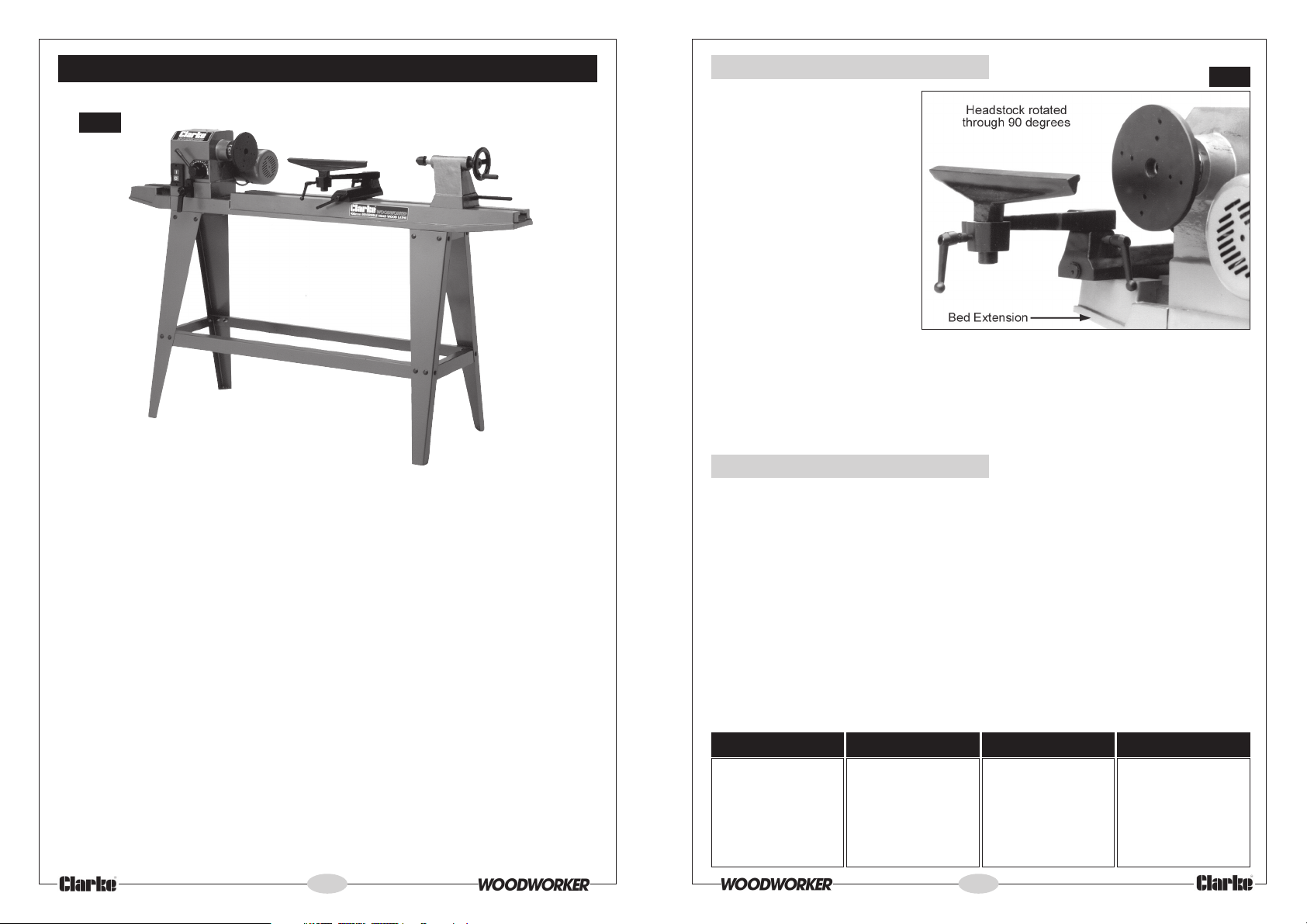
Fig. 1
1. Lay out components in a clean flat area, and ensure that they are ALL are
accounted for. Any deficiencies should be reported to your local dealer
immediately, or please call CLARKE International Parts Dept. on 020 8988 7400
Loose items included are as follows:
1.1 Legs 4 pcs
1.2 Long Cross Members 2 pcs
1.3 Short Cross Members 2 pcs
1.4 Bed mounting Plates 2 pcs
1.5 Face Plate 1 pc
1.6 Bed Extension 1 pc
1.7 Allen Keys 3 pcs
1.8 Carriage Bolts with nuts and washers 24 pcs
1.9 10mm Allen Screw with spring washer 2 pcs
1.10 M8 x 35mm Allen Screw with spring washer 4 pcs
1.11 M8 x 45mm Allen Screw with spring washer 4 pcs
1.12 Headstock clamp handle with spring and washer 1 pc
1.13 Collar hex. Spanner 1 pc
F. The Bed Extension (see Fig. 6)
A Bed Extension (item 52), is
provided so that outboard
turning can take place. It is
used when face plate turning
with larger workpieces, with
the headstock mounted at
90° to the lathe bed, or when it
is desired to work directly in
front of the workpiece, with
the headstock at 180° to its
normal position.
In order that the Tool Rest may
be used, it must first of all be
removed from its position on
the bed by unscrewing the
mounting nut (item 44), completely. It is then mounted on the Bed Extension using
the same attachments. The Headstock is rotated to the desired angle (four
positions are provided), by slackening off the Headstock Clamp (item 24A),
pulling out the locking pin (item 35), rotating the head, and re-locking where
required. Finally the head is re-clamped. The tool rest may be positioned at any
desired angle, remembering to firmly clamp all joints.
Fig. 6
G. Speed Selection
Your Wood Lathe is provided with variable spindle speeds, from 500 to 2000 RPM.
Speed change will only take place with the lathe running. To change speeds, pull
out the spring loaded handle, which locks the speed change lever in place, and
turn the lever to the appropriate speed requirement (Moving the lever clockwise
increases the speed, anticlockwise decreases).
Spindle speeds are dependant upon the size of workpiece being turned, and to
some extent, the type of wood. The following chart is a guide for the spindle
speeds for general turning. You should consult a wood turning manual for more
precise information, and for turning special woods.
It should be noted that the spindle speeds quoted in the Specification chart are
correct to within a 15% tolerance.
NOTE: When a workpiece is completed, or when you have finished with the
machine, always select the slowest speed before switching off.
DIAMETER OF WORK ROUGHING OFF GENERAL CUTTING FINISHING
Under 2" Dia.. 1210 to 1590RPM 1790 to 2000 RPM 1790 to 2000 RPM
2" to 4" Dia. 900 to 1210 RPM 1210 to 2000 RPM 1790 to 2000 RPM
4" to 6" Dia. 620 to 900 RPM 1210 to 1790 RPM 1790 to 2000 RPM
6" to 8" Dia. 620 RPM 900 to 1210 RPM 1200 to 1790 RPM
8" to 12" Dia. 500 RPM 500 to 760 RPM 900 to 1210 RPM
8
13
Page 9
D. For Turning Between Centres
For turning between centres, two hardened Morse Taper centres are provided.
The Live Centre should be gently tapped into the work (at its exact centre previously marked out), using a wooden mallet, and then mounted in the
Headstock Spindle with work attached (refer to ‘The Headstock’ section for
information on mounting the centre).
Move the Tailstock along the bed (with the centre in place), and lock (using
clamp - item 37), in a position where the centre is approximately 1" - 1½” from the
workpiece. Advance the Centre, by turning the feed handle (item 49) until it
makes contact with the work at its exact pre-marked centre. Continue to
advance the Centre whilst simultaneously rotating the work by hand. When it
becomes difficult to turn the work, slacken off the feed about one quarter of a
turn, and lock the Tailstock Spindle.
Note: The Tailstock centre should be lubricated (unless it is a ball bearing type),
using beeswax, tallow, or in some cases, oil - consult a wood turning manual.
E. For Faceplate Turning
Turning which cannot be worked through centres, must be mounted on a
faceplate, or other work-holding device. (Some jobs may require the use of
special chucks).
All face plate work is done by scraping.
Any attempt to use a cutting technique
on edge grain, will result in hogging or
gouging, which may tear the tool out
of your hands.
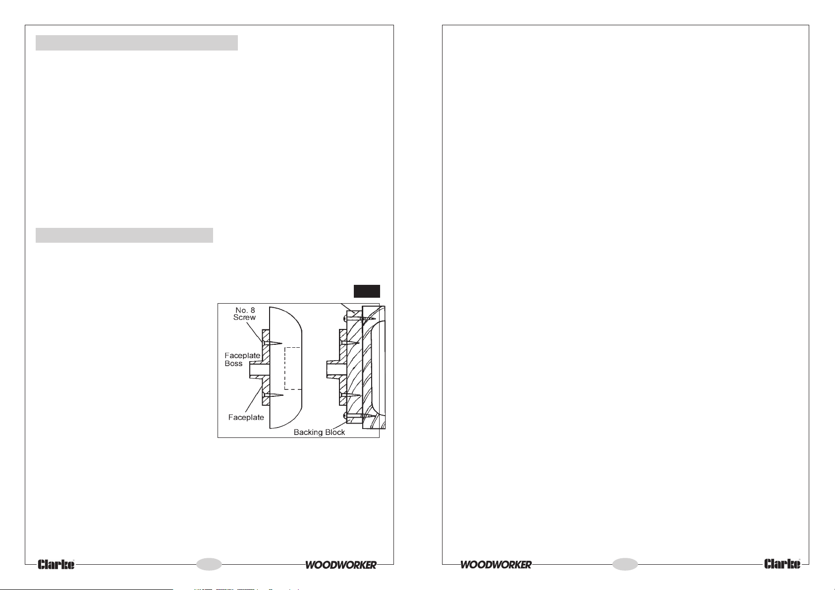
For Faceplate turning, the work (suitably
trimmed so that it is as near to its final
dimension as possible), should be firmly
mounted on to the faceplate, using
screws as appropriate (see fig 5). The
complete assembly is then screwed on
to the headstock spindle, and tightened
securely, by holding the faceplate with
a spanner, via the flats on the
faceplate boss, and turning the spindle
collar using the spanner provided.
The screws used in securing the work to the face plate, must not be of sufficient
length as to interfere with the tool at the final dimension. It may be necessary to
screw the work to a backing piece, depending upon design, or, where screws are
not permissible at all, the work may be glued to a backing piece - fitting a piece
of paper at the joint which will allow for later separation without damaging the
wood.
Fig. 5
2. Thoroughly clean all machined surfaces to remove any protective coating
that may be present. The surfaces should then be lightly oiled.
3. Gently, and with assistance, turn the bed assembly over so that it is resting on
the headstock and tailstock, and to protect those components, rest them on
suitable pieces of packing material. Ensure the unit is completely stable,
adjusting the packing pieces as necessary until it is.
4. Bolt on the two bed mounting plates (item 54B), ensuring they are the right
way round, i.e. the open sections facing each other.
Secure each plate using four M8 Allen screws with washers supplied, ensuring
the 35mm screws are used at the HEADSTOCK end, and the 45mm screws at
the TAILSTOCK end.
5. Bolt the four Legs (item 54A) on to the Bed Mounting Plates (item 54B), using
the 12 Carriage Bolts supplied. Ensure that the legs are on the outside of the
mounting plates, and the bolt heads are on the outside of each leg, firmly
located into the square holes in the leg, and the flat washers are in place
against the inside of the bed mounting plate. LEAVE NUTS FINGER TIGHT ONLY.
6. Bolt on the two Long Cross Members (item 54C), and two Short Cross Members
(item 54D), to the insides of the legs ensuring they are the right way round, (i.e.
the broad flat angle sections are facing the bed).
DO NOT fully tighten the nuts. First rock the leg assembly to ensure there are no
distortions or that no component is under stress. When satisfied fully tighten all
nuts and bolts so far assembled.
7. Should you wish the Bed Extension (item 52), to be a permanent feature, it is
best to bolt it on at this stage. Turn it so that the machined bed side is face
down. Offer it up to the lathe bed at the headstock end, with the mounting
holes facing the lathe bed. Rest the extension on a piece of packing material,
if necessary, whilst lining up the holes in the end of the lathe bed with those in
the extension. Insert the two 10mm Allen screws with spring washers provided,
and tighten them fully.
8. With assistance, lift and turn the complete assembly on to its legs.
9. Attach the Headstock Clamping Handle (item 24A), to its spigot ensuring the
spring and screw are correctly positioned. (See parts diagram)
Your Wood Lathe is now fully assembled, and may be prepared for use.
12
9
Page 10
PREPARATION (Item Nos. Refer to Parts list)
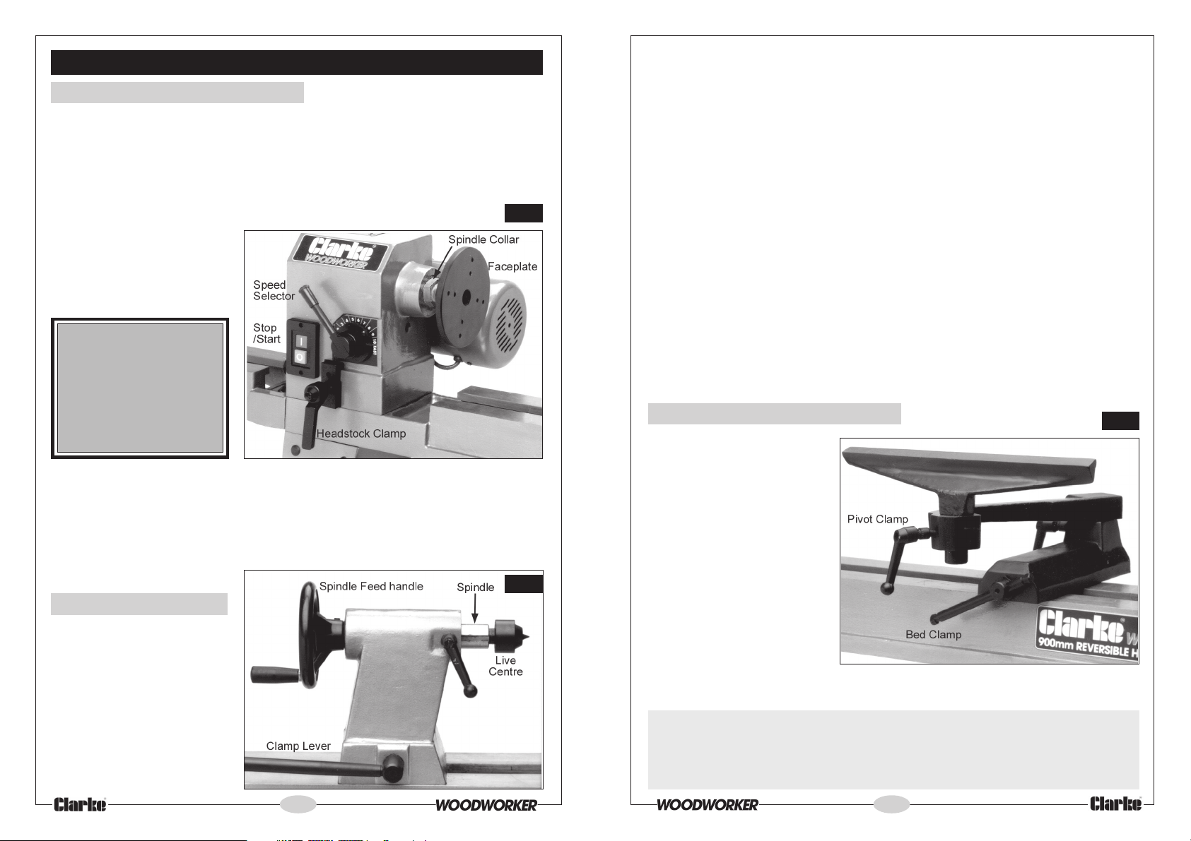
A. The Headstock (see fig.2)
To protect the motor during transit, the headstock is rotated and locked at 90
degrees from its normal position, i.e. with the motor over the lathe bed. Pull out the
Headstock Locking Pin (item 35, and see Fig. 7), against spring pressure, allowing
the Headstock to be rotated through 90 degrees so that the spindle faces the
tailstock. Release the locking pin which will reassert itself locking the headstock in
the “in line” position.
The Headstock is further
secured to the bed by a
clamp (see fig. 2). The clamp
should be firmly applied
using the Handle (item 24A),
and the headstock should
then be solid with the bed.
WARNING: If there is any
movement of the
headstock whatsoever
when the clamp is
tightened, DO NOT start
the machine. Refer to
the Maintenance
section for adjustments.
The Headstock Spindle is provided with an internal No. 2 Morse Taper, which will
accommodate a suitably tapered centre, and on to which the workpiece may
be mounted. One ‘Live Centre’ is provided which is mounted by simply inserting it
into the spindle. Refer to “Turning between Centres” for further information.
To remove the Live Centre, insert a suitable piece of round bar into the back of the
spindle until it comes into contact with the centre. Give the bar a sharp blow, and
the centre will disengage.
B. The Tailstock
The tailstock is held firm to the
bed by means of a clamp
(see fig 3). Turning the clamp
lever (item 50) anticlockwise,
by approx. one third of a turn,
should release the tailstock,
allowing it to slide along the
bed to the desired position,
and turning the lever back
again should firmly lock the
tailstock in that position.
10
Fig. 2
Fig. 3
If the tailstock fails to move when the clamp is released, or fails to lock when the
clamp lever is turned clockwise through approx. one third of a turn, the tailstock
securing nut, beneath the tailstock (item 44), is either too loose or too tight.
Adjust the nut so that with the clamp lever turning through approx one third of a
turn, the tailstock slides freely when unclamped, but is held firmly when clamped.
The Tailstock Spindle is provided with an internal No. 2 Morse Taper, and a Morse
tapered centre is provided for ‘between centres’ turning, but any No. 2 Morse
Taper tool, such as a drill chuck, may be mounted and used when required.
To mount a tool in the spindle, ensure the spindle clamp (item 37) is not applied,
then turn the spindle feed handle (item 49) clockwise, thereby extending the
spindle until the tools’ Morse Tapered shank can be inserted to its full length,
locking it into place.
To remove a tool from the tailstock, first slacken off the spindle clamp, allowing the
spindle feed handle (item 49) to be turned anticlockwise, thereby withdrawing
the tool from the workpiece.
Unclamp the tailstock and move it well away from the workpiece. Continue to turn
the spindle feed handle anticlockwise until resistance is felt. At this point, back off
slightly, and then turn the handle sharply, thereby breaking the seal between the
Morse tapered tool and the spindle, allowing the tool to be removed.
Support the tool during this operation, to prevent the possibility of it dropping on to
the lathe bed when it becomes detached.
C. Tool Rest Adjustment
The tool rest is adjustable to
almost any position, using a
combination of pivots and
clamps. The Bed Clamp
(items 41 to 44), when
slackened, allows the tool
rest to slide along the bed to
its desired position and is
adjusted in a similar manner
to the Tailstock Clamp. i.e.
One third of a turn should
clamp or unclamp the
toolrest.
The Tool Rest should always
be on the centre line, and as
close as possible, to the workpiece, but for correct positioning, depending upon
the work being undertaken, consult a wood turning manual.
IMPORTANT:
Fig. 4
Always ensure the Tool Rest clamps are firmly applied, as there is a danger
that the tool rest could swing into the rotating workpiece, with drastic
consequences.
11
 Loading...