

Page 1
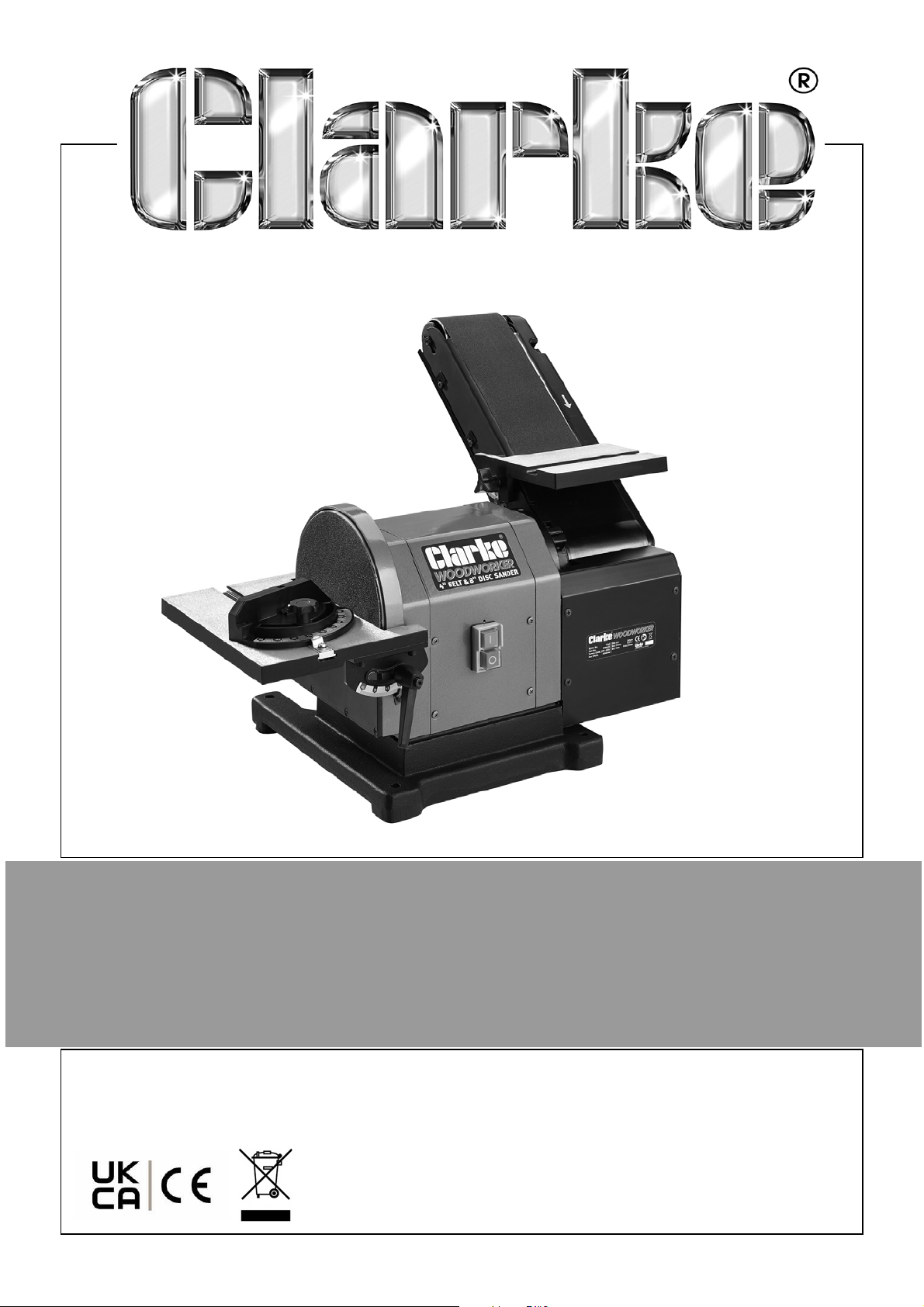
BELT & DISC SANDER
MODEL NO: CS48
PART NO: 6500430
OPERATION & MAINTENANCE
INSTRUCTIONS
ORIGINAL INSTRUCTIONS
DL1022 - ISS 5
Page 2

INTRODUCTION
Thank you for purchasing this CLARKE product.
Before attempting to use this product, please read this manual thoroughly and
follow the instructions carefully. In doing so you will ensure the safety of yourself
and that of others around you, and you can look forward to your purchase
giving you long and satisfactory service.
GUARANTEE
This product is guaranteed against faulty manufacture for a period of 12
months from the date of purchase. Please keep your receipt which will be
required as proof of purchase.
This guarantee is invalid if the product is found to have been abused or
tampered with in any way, or not used for the purpose for which it was
intended.
Faulty goods should be returned to their place of purchase, no product can
be returned to us without prior permission.
This guarantee does not effect your statutory rights.
IN THE BOX
The following should be supplied inside the box.
If any parts are missing, please contact your local CLARKE dealer.
• 1 x Belt disc sander
• 1 x 200mm P80 sanding disc (Fitted)
• 1 x 100mm x 914mm 4"x 36" Sanding belt (Fitted)
• 1 x Disc table 265x150
• 1 x Belt table 170 x 125
•1 x Dust bag
•1 x Wrench
•1 x Angle Gauge
• 1 x Instruction manual
2
Parts & Service: 020 8988 7400 / E-mail: [email protected] or [email protected]
Page 3

GENERAL SAFETY RULES
1. ALWAYS learn the machines applications, limitations and the specific
potential hazards. Read and become familiar with the entire operating
manual.
2. ALWAYS use a face or dust mask if the operation is particularly dusty.
3. AlWAYS check for damage before using the machine, check for alignment
of moving parts, breakage of parts, and any other condition that may
affect the machines operation. Damage should be properly repaired or
the part replaced. If in doubt, DO NOT use the machine. Consult your local
dealer.
4. ALWAYS disconnect the machine from the power supply before servicing
and when changing accessories.
5. ALWAYS wear safety goggles, manufactured to the latest European Safety
Standards. Everyday eyeglasses do not have impact resistant lenses, and
are not safety glasses.
6. ALWAYS keep work area clean. Cluttered areas and benches invite
accidents.
7. ALWAYS ensure that adequate lighting is available. Ensure that lighting is
placed so that you will not be working in your own shadow.
8. ALWAYS keep children away. All visitors should be kept a safe distance from
the work area, especially when the machine is being used.
9. ALWAYS maintain machine in top condition. Keep tools/machines clean for
the best and safest performance. Follow maintenance instructions.
10. ALWAYS handle with extreme care and do not carry the tool/machine by its
electric cable, or pull on the cable to disconnect it from the power supply.
11. ALWAYS ensure the switch is off before plugging in to mains. Avoid
accidental starting.
12. ALWAYS concentrate on the job in hand, no matter how trivial it may seem.
Be aware that accidents are caused by carelessness due to familiarity.
13. ALWAYS keep your proper footing and balance at all times - don’t
overreach. For best footing, wear rubber soled footwear. Keep floor clear
of oil, scrap wood, etc.
14. ALWAYS dress properly. Loose clothing or jewellery may get caught in
moving parts. Wear protective hair covering to contain long hair.
15. ALWAYS guard against electric shock. Avoid contact with earthed surfaces
- pipes, radiators etc.
3
Parts & Service: 020 8988 7400 / E-mail: [email protected] or [email protected]
Page 4

16. NEVER operate machine while under the influence of drugs, alcohol or any
medication.
17. NEVER leave machine running unattended. Turn power off. Do not leave
the machine until it comes to a complete stop.
18. NEVER force the machine, it will do a better and safer job at the rate for
which it was designed.
19. NEVER use power tools in damp or wet locations or expose them to rain. Do
not use in an explosive atmosphere (around paint, flammable liquids etc.).
Avoid dangerous environments.
20. If the tool begins to make an abnormal noise, or produce excessive
vibrations, smoke or burning odour, turn the tool off immediately and do
not operate, until repaired.
EXTRA PRECAUTIONS FOR BELT/DISC SANDERS
1. ALWAYS wear ear protectors/defenders when using this machine.
2. ALWAYS wear a dust mask when using this machine. Be aware that harmful
or toxic dust could be produced when sanding some timbers.
3. ALWAYS use the table to support the workpiece.
4. ALWAYS make sure the table and attachments are secure before starting.
5. ALWAYS maintain a clearance of 1.6 mm between table and sanding disc.
6. ALWAYS hold the workpiece firmly so that it cannot be torn from your
hands.
7. ALWAYS feed the workpiece against the direction of rotation of the disc. i.e
the right side of the disc.
8. ALWAYS keep the mains cable well away from the machine and ensure an
adequate electrical supply is close at hand so that the operation is not
restricted by the length of the cable.
9. ALWAYS use a dust extraction bag connected to the dust extraction port.
10. ALWAYS ensure that nails or foreign objects have been removed from a
workpiece beforehand. Nails etc. will destroy the belt or disc.
12. NEVER sand pieces which cannot be held firmly by hand.
WARNING: WARNING: USE ONLY FOR SANDING WOOD. DO NOT USE FOR
MATERIALS CONTAINING ASBESTOS, PAINTED SURFACES OR MATERIALS
WHICH EMIT TOXIC PARTICLES.
4
Parts & Service: 020 8988 7400 / E-mail: [email protected] or [email protected]
Page 5
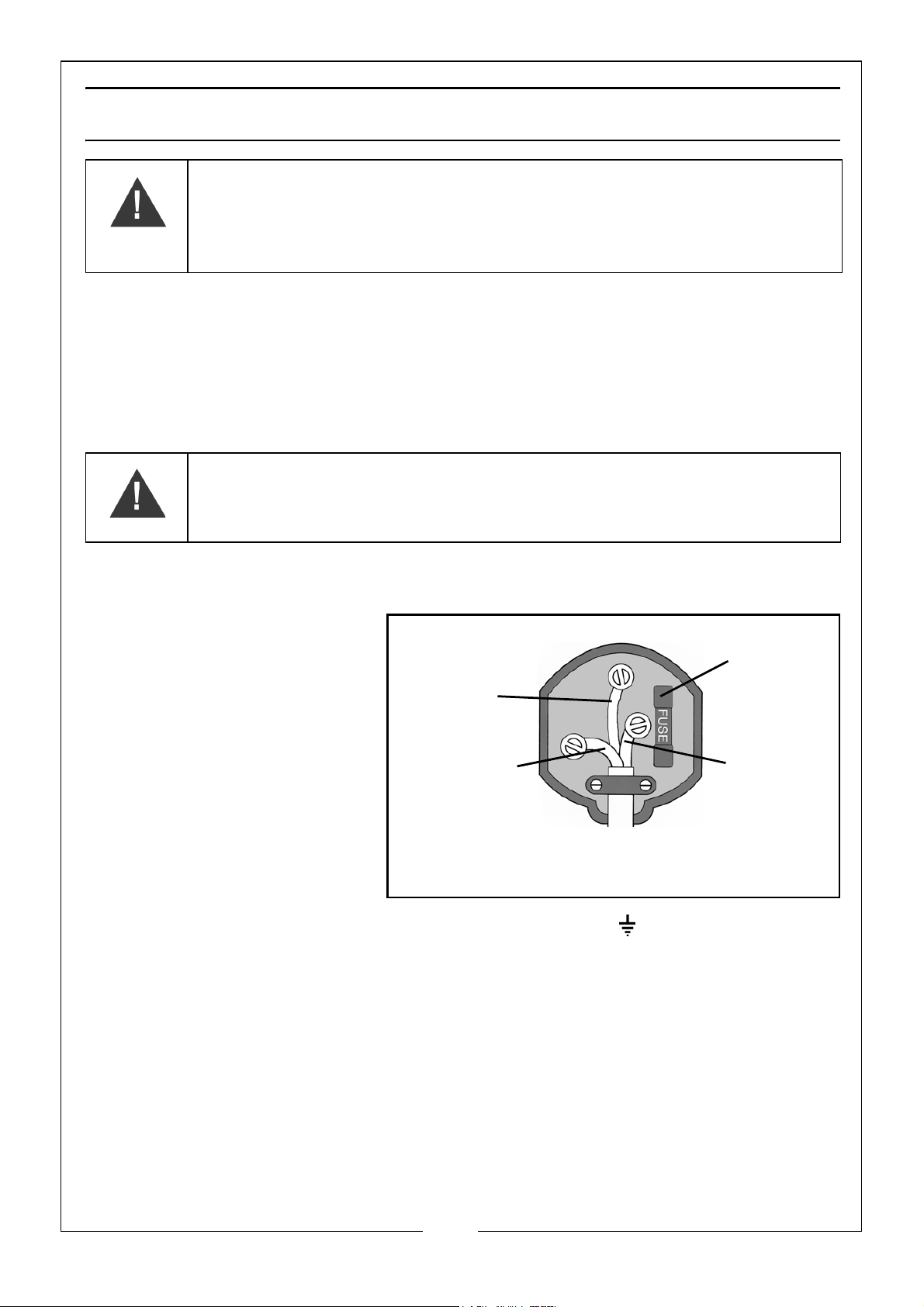
ELECTRICAL CONNECTIONS
Plug must be BS1363/A approved.
Always fit
Ensure that the outer sheath of
Neutral
(Blue)
Live
(Brown)
Earth
(Green and
a 10 Amp
the cable is firmly held by the clamp
fuse.
Yellow)
WARNING: READ THESE ELECTRICAL SAFETY INSTRUCTIONS
THOROUGHLY BEFORE CONNECTING THE PRODUCT TO THE MAINS
SUPPLY.
Connect the mains lead to a standard, 230 Volt (50Hz) electrical supply
through an approved 13 amp BS 1363 plug, or a suitably fused isolator switch.
If the plug has to be changed because it is not suitable for your socket, or
because of damage, it must be removed and a replacement fitted, following
the wiring instructions shown below. The old plug must be discarded safely, as
insertion into a power socket could cause an electrical hazard.
WARNING: THE WIRES IN THE POWER CABLE OF THIS PRODUCT ARE
COLOURED IN ACCORDANCE WITH THE FOLLOWING CODE:
BLUE = NEUTRAL BROWN = LIVE YELLOW AND GREEN = EARTH
If the colours of the wires in the power cable do not agree with the markings
on the plug.
We strongly recommend that this machine is connected to the mains supply
through a Residual Current Device (RCD)
If you are not sure, consult a qualified electrician. DO NOT try to do any repairs.
•The BLUE wire must be
connected to the
terminal which is
marked N or coloured
black.
•The BROWN wire must
be connected to the
terminal which is
marked L or coloured
red.
•The YELLOW AND
GREEN wire must be
connected to the terminal which is marked E or or coloured green.
5
Parts & Service: 020 8988 7400 / E-mail: [email protected] or [email protected]
Page 6
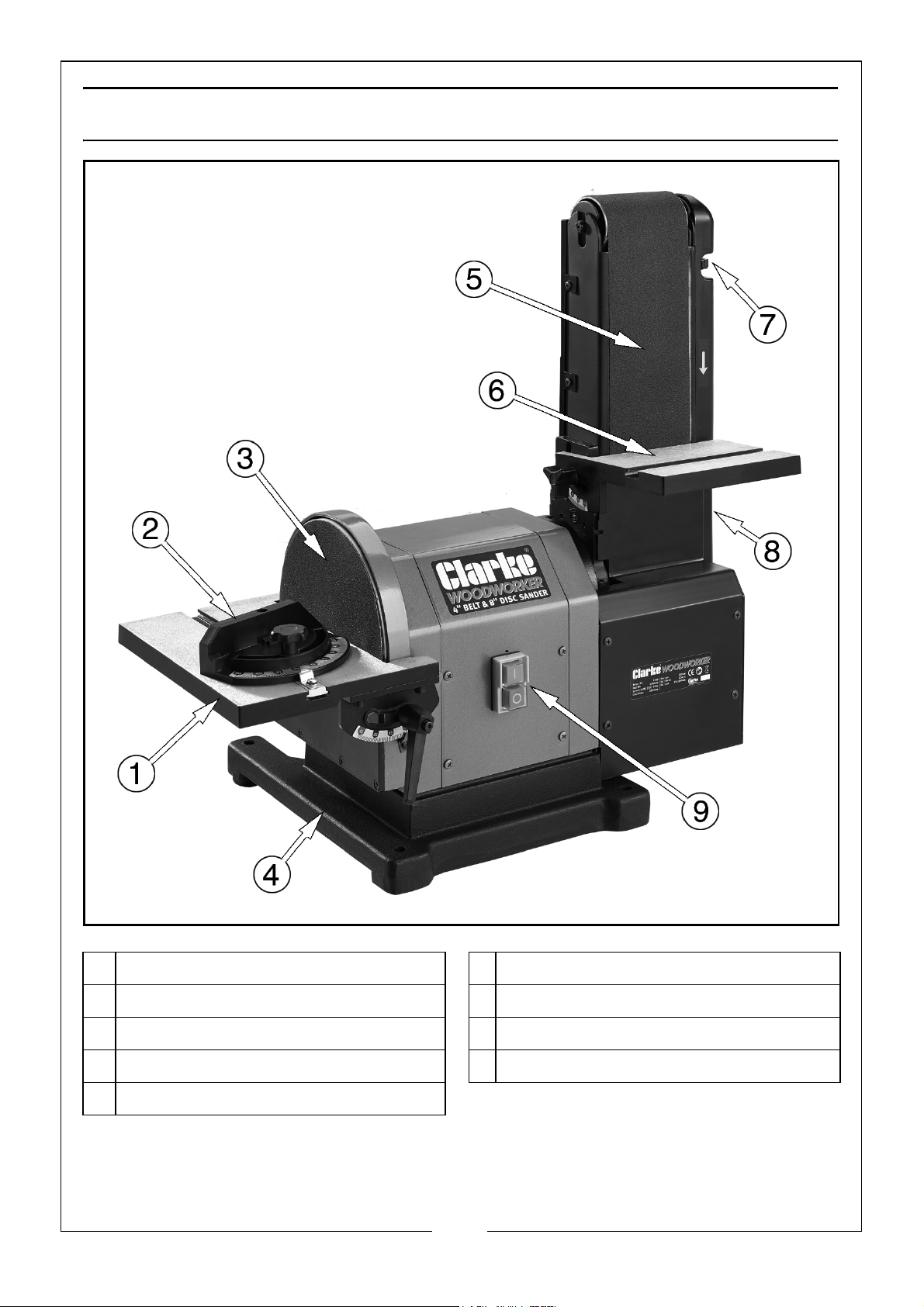
OVERVIEW
1 Disc Sander Table 6 Sanding Belt Table
2 Adjustable Mitre Gauge 7 Tracking Adjustment Dial
3 8” Disc Sander 8 Belt Tensioning Lever
4 Base With Mountiong Holes 9 On/off Button
5 4” Sanding Belt
6
Parts & Service: 020 8988 7400 / E-mail: [email protected] or [email protected]
Page 7
ASSEMBLY
CAUTION: THE SANDER MUST ASSEMBLED BEFORE USE. DO NOT PLUG UNIT INTO
POWER SOURCE UNTIL THE MACHINE HAS BEEN COMPLETELY ASSEMBLED.
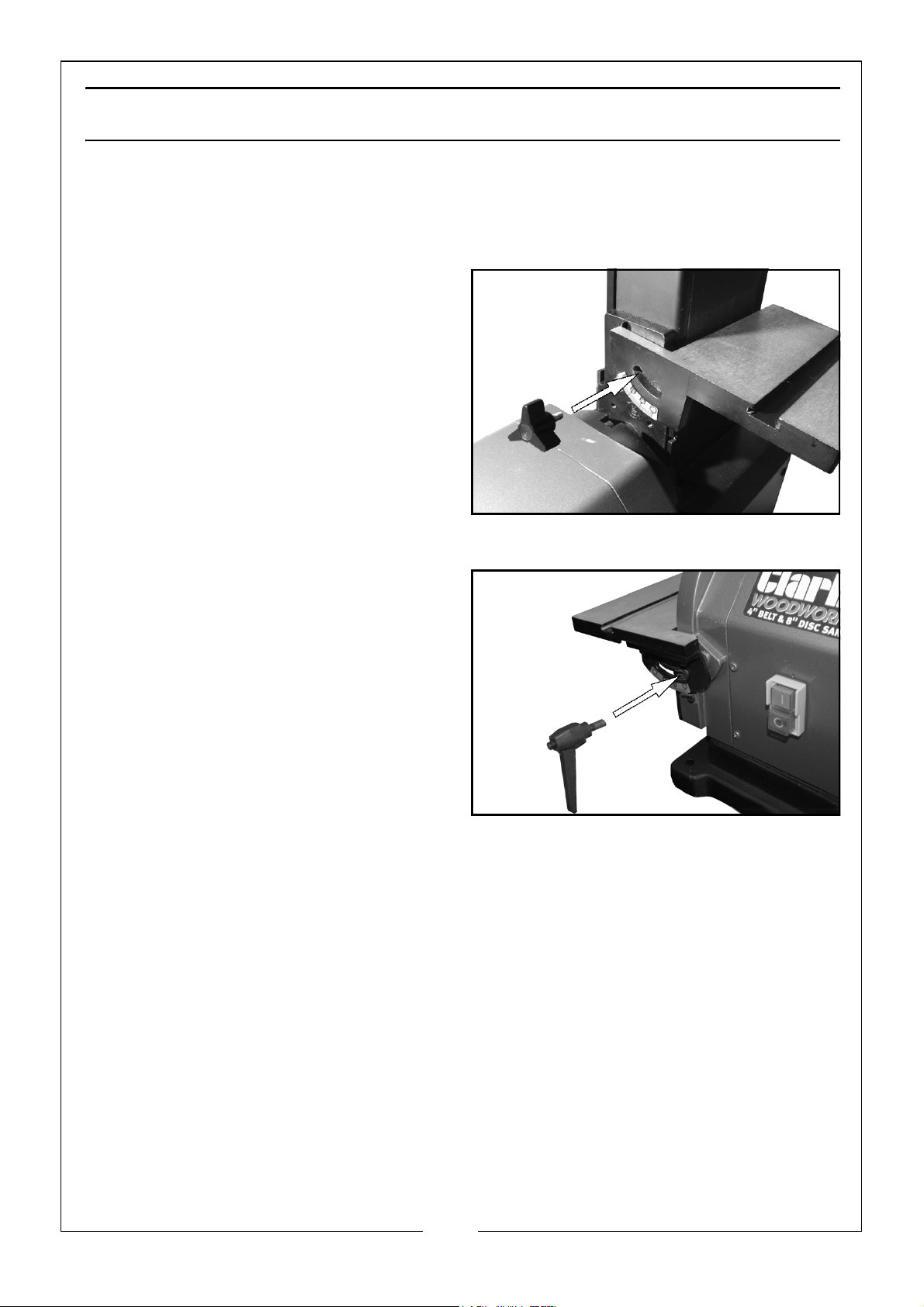
Installing The Belt Sander Table
1. Attach the belt sander table to
frame with the handwheel and
washer supplied.
• Do not overtighten the
handwheel.
MOUNTING THE DISC SANDER TABLE
1. Put the disc sander table into
position as shown.
2. Put a washer on to the thread of
the locking handle and insert the
thread through the radius slot.
3. Turn the locking handle clockwise
to tighten.
4. Repeat on the other side.
7
Parts & Service: 020 8988 7400 / E-mail: [email protected] or [email protected]
Page 8
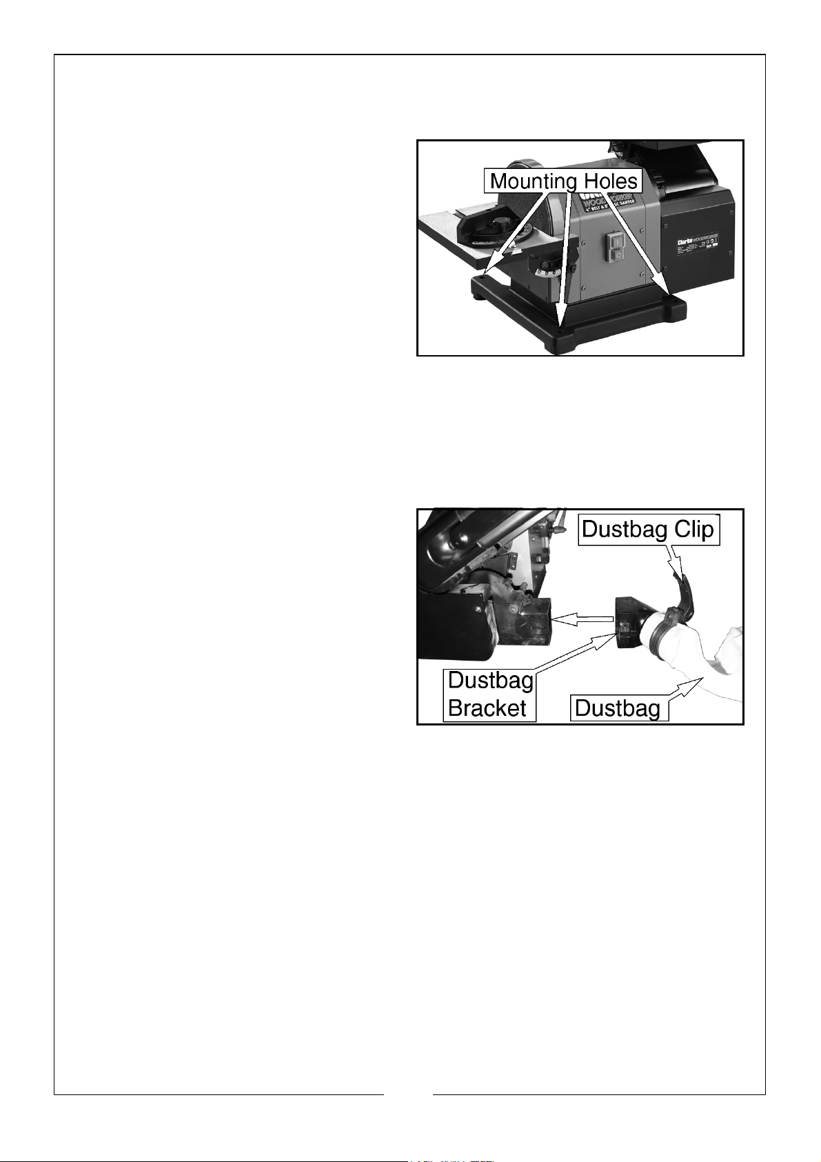
MOUNTING THE SANDER ON TO A WORKBENCH
Attach the machine to a workbench or stand before use.
1. Position the machine on the
workbench.
2. Mark the workbench through the
mounting holes in the sander
base.
3. Drill holes in the workbench at the
marks.
4. Use long bolts, spring washers and
nuts (not supplied), to secure the
machine to the workbench.
MOUNTING THE DUSTBAG TO THE SANDER
The sander is provided with a dust extraction facility. Please note however,
that this does not preclude the user from wearing a face mask to prevent the
inhalation of dust particles
1. Use the dustbag clip to secure the
dustbag to the dustbag bracket
as shown,
2. Fit the dustbag bracket over the
dust extraction port as indicated.
8
Parts & Service: 020 8988 7400 / E-mail: [email protected] or [email protected]
Page 9
OPERATION
WARNING: NEVER TOUCH THE SANDING DISC OR BELT WHILE IT IS
MOVING, DO NOT TOUCH THE WORK PIECE AFTER SANDING, IT COULD BE
VERY HOT.
WARNING: ALWAYS WEAR SAFETY GLASSES WHEN OPERATING THE
SANDER
CAUTION: ALWAYS MAKE SURE THE DISC SANDER TABLE AND BELT SANDER TABLE
ARE PROPERLY ADJUSTED AND SECURE BEFORE USE.
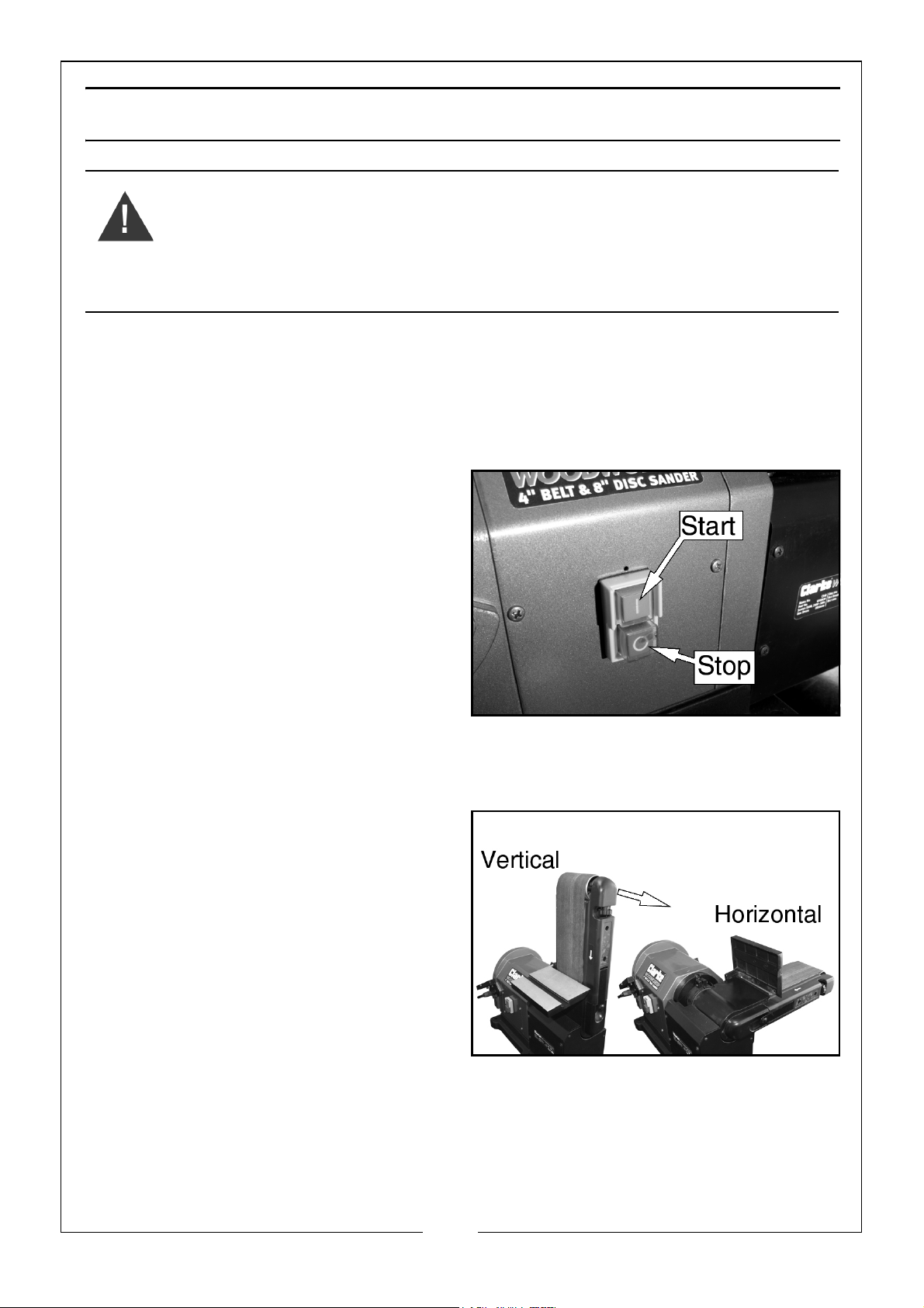
ON/OFF BUTTONS
The On/Off buttons are located on the front of the machine.
1. Push the GREEN button (I) to turn
the machine on.
2. Push the RED button (0) to turn the
machine off.
• If a failure occurs in the power
supply the machine will stop
automatically. It will be
necessary to push the GREEN
button again to continue work.
BELT SANDING
HORIZONTAL AND VERTICAL SANDING
You can use the sanding belt in the
vertical or horizontal position.
To change from one position to the
other:
1. Manually move the sanding belt
to the necessary position.
9
Parts & Service: 020 8988 7400 / E-mail: [email protected] or [email protected]
Page 10
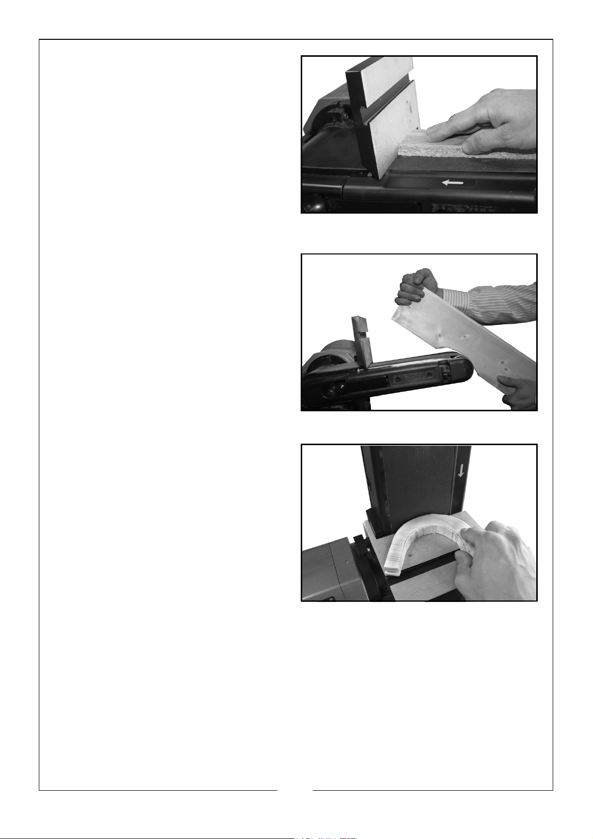
SURFACE SANDING ON THE BELT
When sanding flat wide surfaces hold
the work tightly to the surface of the
belt and against the belt sander
table. Keep your fingers away from
the sanding belt and use a push or
hold-down stick if possible.
• Exercise extra care when
working with very thin pieces.
• Only apply sufficient pressure to
allow the sanding belt to remove material.
SANDING INSIDE CURVES
You can sand inside-curves using the
idler drum end of the belt.
• Hold the work tightly.
• Keep fingers away from the
sanding belt.
• Keep the curve held against the
idler drum, moving the work
gradually back and forth across
the drum.
SANDING OUTSIDE CURVES
• Keep the curve pressed against
the sanding belt, moving the
work from left to the right of the
belt.
• Make sure that you hold the
work tightly against the surface
of the table.
10
Parts & Service: 020 8988 7400 / E-mail: [email protected] or [email protected]
Page 11
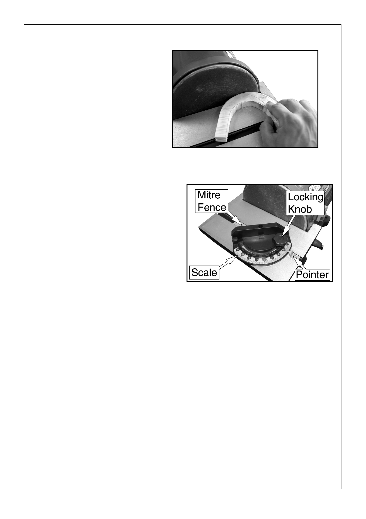
SANDING DISC
• To stop the work from lifting,
only use the right hand side
of the sanding disc.
• Keep the work pressed
against the sanding disc,
moving from the centre of
the disc to the right hand
edge.
• Make sure that you hold the
work tightly against the
surface of the table.
MITRE GAUGE
The mitre gauge can be used on both
tables,
1. Loosen the locking knob.
2. Set the mitre fence to the
necessary angle.
• You can adjust the mitre gauge
o
60
(right or left).
3. Tighten the locking knob.
SANDING SMALL SURFACES USING THE MITRE GAUGE
Use the mitre gauge for sanding small end surfaces on the sanding disc.
NOTE: Always move the workpiece across the right side of the sanding disc
and hold the work down tightly onto the table surface.
11
Parts & Service: 020 8988 7400 / E-mail: [email protected] or [email protected]
Page 12
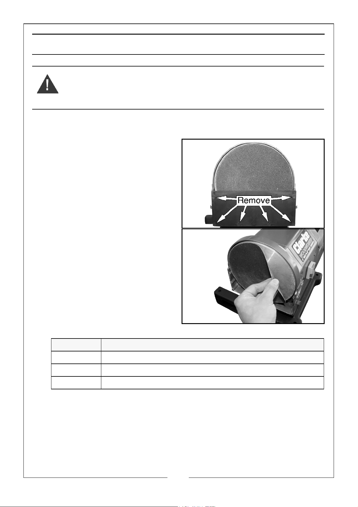
CHANGING THE SANDING DISCS
WARNING: TURN THE POWER OFF AND REMOVE THE PLUG FROM THE
OUTLET BEFORE CHANGING THE SANDING DISC.
1. Remove the mitre gauge and work table. See “Mounting The Disc Sander
Table” on page 7.
2. Remove the disc guard screws
and disc guard.
3. Remove the sanding disc from the
disc plate.
• The abrasive discs are attached
to the plate with a pressuresensitive adhesive.
4. Make sure that the disc plate is
clean.
• Replacement sanding discs are
available from your Clarke
dealer.
Grit Part number
Fine 6500440
Medium 6500441
Coarse 6500442
NOTE: ‘Hook and loop’ sanding discs cannot be used with this machine.
5. Remove the paper backing from the new abrasive disc.
6. Align the edge of the abrasive disc with the plate and press the disc into
position, leaving no loose edges.
7. Replace the disc guard, disc guard screws and work table.
NOTE: ‘Hook and loop’ sanding discs cannot be used with this machine.
12
Parts & Service: 020 8988 7400 / E-mail: [email protected] or [email protected]
Page 13
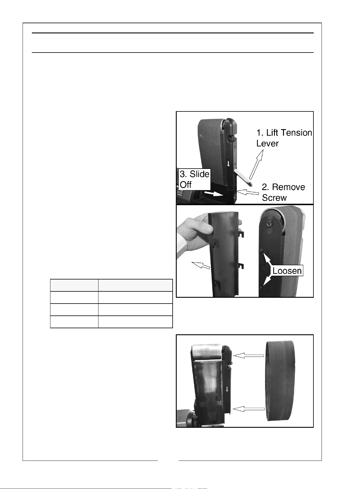
CHANGING THE SANDING BELTS
CAUTION: CHECK THE INSIDE OF THE BELT FOR A “DIRECTION ARROW”. IF PRESENT,
INSTALL THE BELT WITH THE ARROW POINTING IN THE SAME DIRECTION AS THE
DIRECTION INDICATOR ON THE HOUSING.
1. Remove the table See “Installing The Belt Sander Table” on page 7.
2. Pull the bottom of the tension lever
out to release the belt tension.
3. Remove the screw from the lower
cowling and slide the cowling off.
4. Loosen the screws shown and lift
off the rear plate.
5. Remove the sanding belt from the
rollers.
• Replacement sanding belts are
available from your Clarke
dealer.
Grit Part number
Fine 6502096
Medium 6500808
Coarse 6502101
6. Fit the new belt onto the rollers.
7. Replace all the parts removed in
reverse order.
8. Engage the tension lever to apply
tension to the belt.
9. Check the belt tracking
(described in “Belt Tracking” on
page 14) before use and adjust if
necessary.
13
Parts & Service: 020 8988 7400 / E-mail: [email protected] or [email protected]
Page 14
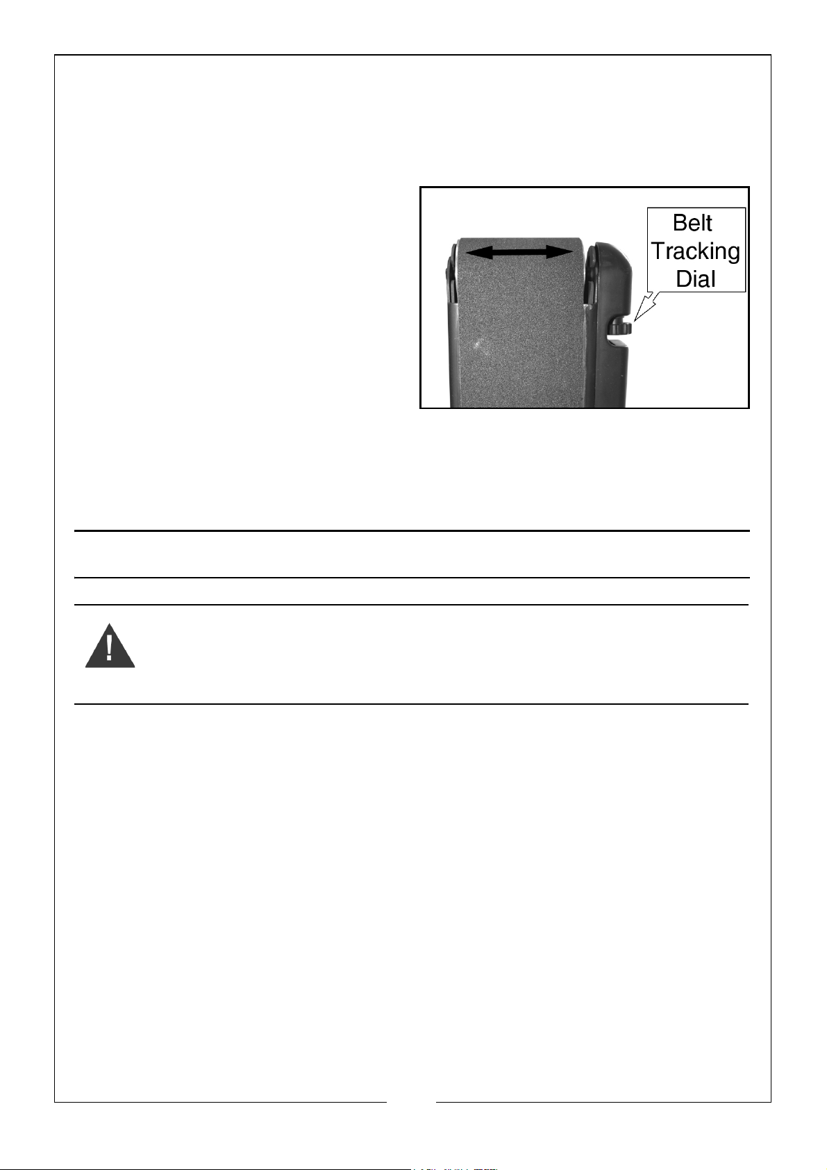
BELT TRACKING
The belt-tracking adjustment is set at the factory so that the abrasive belt will
run true on the drums. If, however, the belt should track to one side or the
other, an adjustment can be made by turning the tracking knob.
TO TRACK THE SANDING BELT
1. Use your hand to roll the belt
towards the belt sander table.
• If the sanding belt does not
move to either side after several
full turns, it is tracking correctly.
• If not adjust the belt tracking
dial slightly and roll the belt
again.
•Repeat as necessary.
NOTE: Do not make large adjustments to the belt tracking dial and remember
it may take some time for the belt to react to any change you make.
MAINTENANCE
WARNING: ALWAYS DISCONNECT TOOL FROM POWER SOURCE BEFORE
MAKING ANY ADJUSTMENTS, INSTALLING OR PERFORMING
MAINTENANCE.
CAUTION: TOOL SERVICING MUST BE PERFORMED ONLY BY QUALIFIED REPAIR
PERSONNEL. SERVICE OR MAINTENANCE PERFORMED BY UNQUALIFIED
PERSONNEL COULD RESULT IN A RISK OF INJURY. WHEN SERVICING A TOOL, USE
ONLY IDENTICAL REPLACEMENT PARTS.
CAUTION: FOLLOW INSTRUCTIONS IN THE MAINTENANCE SECTION OF THIS
SERVICE MANUAL. USE OF UNAUTHORISED PARTS OR FAILURE TO FOLLOW
MAINTENANCE INSTRUCTIONS MAY CREATE A RISK OF ELECTRIC SHOCK OR
INJURY.
1. Clean the machine, belt and disc after each use.
2. Keep the machine dry, clean and free of oil and grease.
3. Keep the machine in a safe and dry area, out of reach of children.
4. During use, sanding belts and discs can become dirty with sanding debris.
Use a stick belt cleaner (available at most hardware stores) to remove
unwanted material from the belt/disc.
14
Parts & Service: 020 8988 7400 / E-mail: [email protected] or [email protected]
Page 15
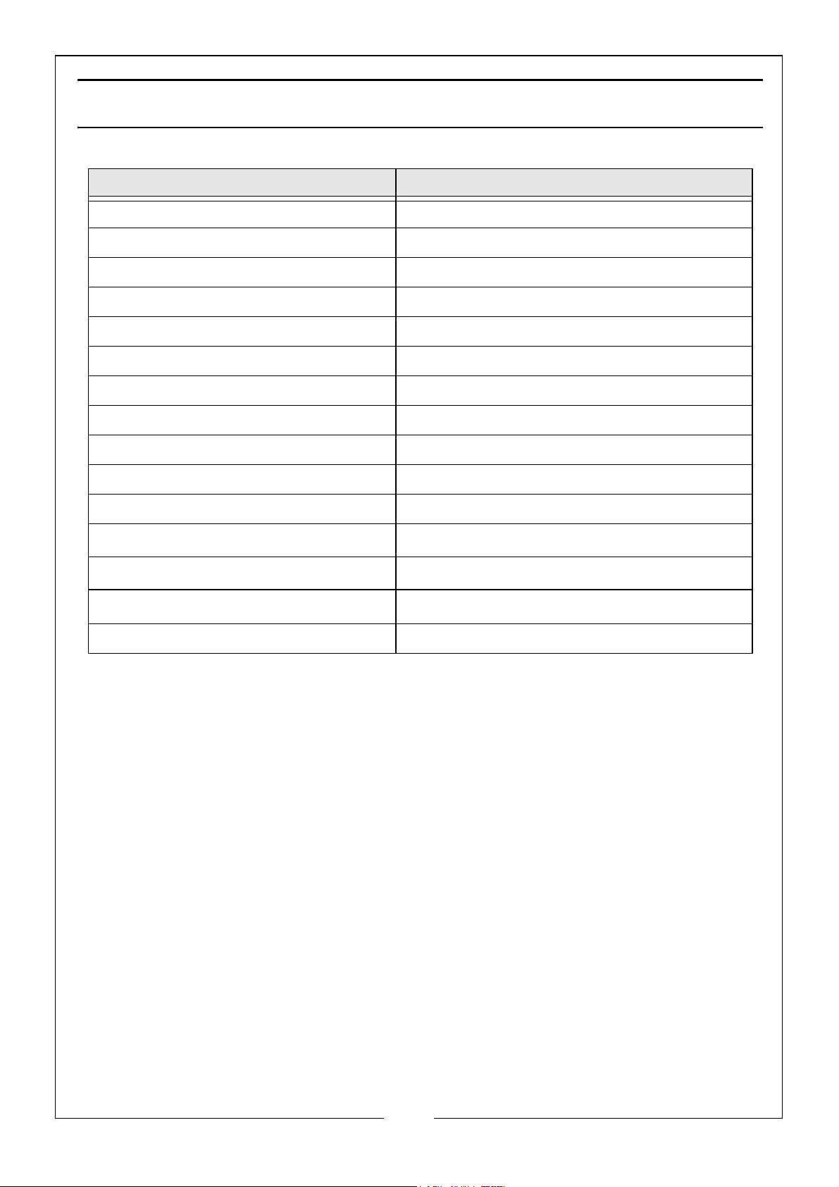
SPECIFICATIONS
Motor 230V, 50Hz, 1ph
Input Power 500 Watts
Fuse Rating 10 Amps
Sanding Disc Diameter 8” (203 mm)
Sanding Belt Size (W x L) 4” x 36” (914 x 100 mm)
Sanding Belt Speed 9.3 m/s
Sanding Table Dimensions (L x W) 265 x 150 mm
Table Angle Range 0-45 degrees
Mitre Guide Angle Range 0-60 degrees (left and right)
Net Weight 23.3 kg
Dimensions (LxWxH) 550 x 590 x 380 mm
Sound Pressure Level dB L
Sound Power Level dB L
WA
Vibration
pA
77.9 dB (A) (No Load)
90.5 dB (A) (No Load)
<2.5 m/s
Part No 6500430
2
15
Parts & Service: 020 8988 7400 / E-mail: [email protected] or [email protected]
Page 16
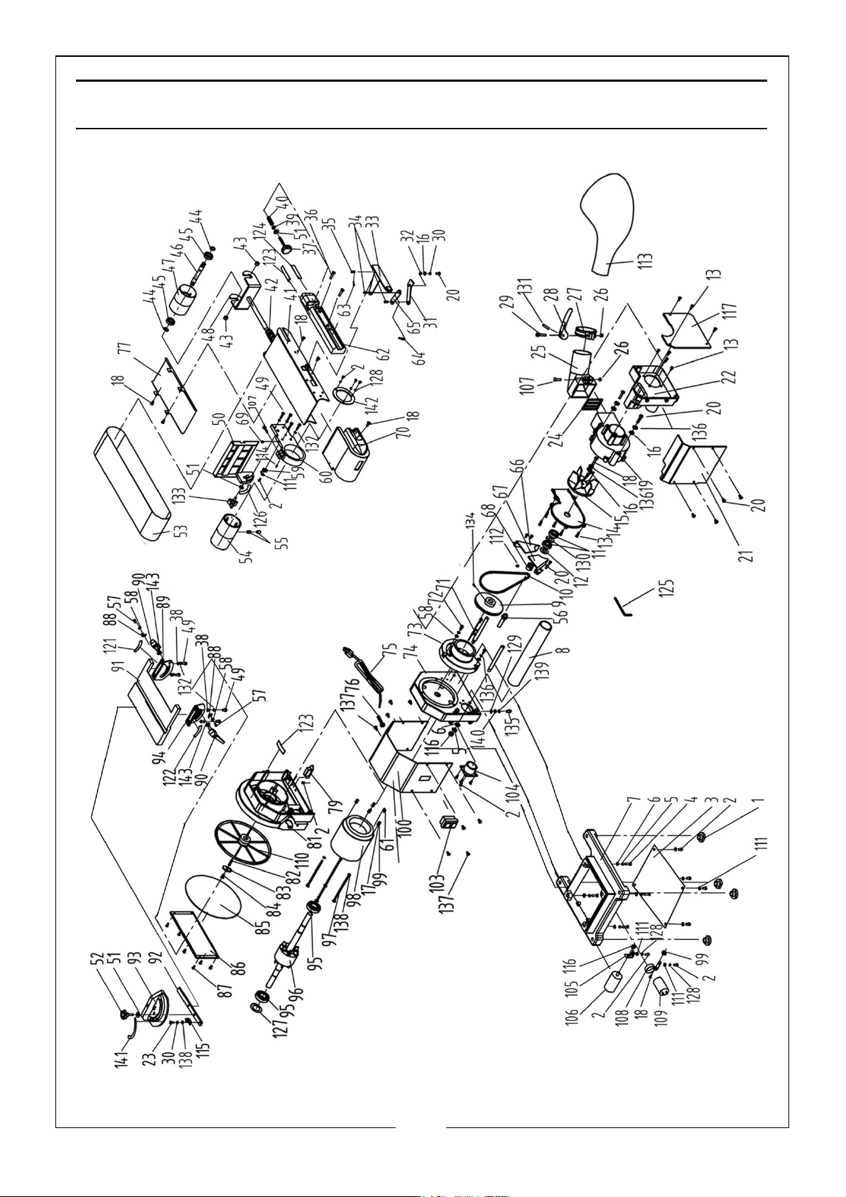
Page 17
No Description No Description
1 Rubber Foot 34 Pin 5×8
2 Philips Screw M4×10 35 Pin 5×10
3 Bottom Plate 36 Philips Screw M5×25
4 Philips Screw (White) M8×25 37 Belt Tracking Knob
5 Lock Washer (White) 38 Flat Washer
6 Flat Washer (White) 39 Rubber Washer
7 Base 40 Adjuster Spring
8 Connecting Tube 41 Belt Frame
9 Driven Pulley 42 Tension Spring
10 Poly-v- Belt 43 Sleeve
11 Bearing 6000rz 44 Spring Washer D12
12 Spring Washer D26 45 Bearing 6001rz
13 Philips Screw St4.2×15 46 Idler Shaft
14 Fan Cover 47 Idler Pulley
15 Fan 48 Belt Tension Assembly
16 Big Washer 49 Inner Hex Screw M6×12
17 Standard Spring Washer 50 Belt Working Table
18 Philips Screw M5×16 51 Big Washer
19 Fan Housing 52 Mitre Gauge Knob
20 Philips Screw M5×10 53 Sanding Belt
21 Front Cover 54 Drive Pulley
22 Dust Storage Box 55 Inner Hex Screw M8×12
23 Philips Screw (White) M5×8 56 Collector Shaft
24 Exhaust Cover 57 Philips Screw M5×8
25 Dust Exhaust 58 Flat Washer
26 I Type Hex Nut M6 59 Work Table Angle Point
27 Dust Bag Clamp 60 Belt Frame Connect
28 Clamp Handle 61 Cable Gland Bushing
29 Screw M6×40 62 Belt Cover
30 Tooth Lock Washer 63 Pin 2x10
31 Belt Tension Lever 64 Spring Washer
32 Sleeve 65 Connecting Plate
33 Tension Handle 66 Right Cover
17
Parts & Service: 020 8988 7400 / E-mail: [email protected] or [email protected]
Page 18
No Description No Description
67 Left Cover 103 Switch
68 Small Pulley Drive 104 Tube Connector
69 Philips Screw & Flat Washer
105 Capacitor Support1
Assembly M4x12
70 Belt Exhaust 106 Capacitor
71 Collector Mounting Shaft 107 Inner Hex Screw M6×25
72 Inner Hex Screw M5×20 108 Capacitor Support 2
73 Belt Mounting Plate 109 Capacitor
74 End Cap 110 Disc Plate
75 Power Cord 111 Flat Washer
76 Strain Relief 112 Inner Hex Screw M5×8
77 Belt Protection Plate 113 Dust Bag
79 Relay 114 Position Shaft
81 Left End Cap 115 Mitre Gauge Pointer
82 Key 5x5x15 116 I Type Hex Nut M8
83 Washer 117 Dust Box Cover
84 Philips Screw M6×16 Left 121 Scale Label Left
85 Abrasive Disc 122 Scale Label Right
86 Disc Cover 123 Rotation Label
87 Philips Screw M4×10 124 Belt Tension Label
88 Angle Pointer 125 Inner Hex Wrench S=5
89 Disc Left Support 126 Scale Label
90 Handle Assembly 127 Spring Washer D40
91 Disc Work Table 128 Standard Spring Washer
92 Mitre Gauge Bar 129 Tooth Lock Washer
93 Mitre Gauge 130 Bearing Bushing
94 Disc Right Support 131 Spring Pin 4x22
95 Bearing 6203rz 132 Standard Spring Washer
96 Rotor 133 Disc Work Table Knob
97 Philips Screw M5×180 134 Inner Hex Screw M5×12
98 Stator 135 Philips Screw M4×10
99 I Type Hex Nut M5 136 Standard Spring Washer
100 Motor Cover 137 Philips Screw M5×10
18
Parts & Service: 020 8988 7400 / E-mail: [email protected] or [email protected]
Page 19
No Description No Description
139 Lock Washer(White) 142 Support Board
140 Flat Washer(White) 143 Flat Washer
141 Quadrent Scale Lable
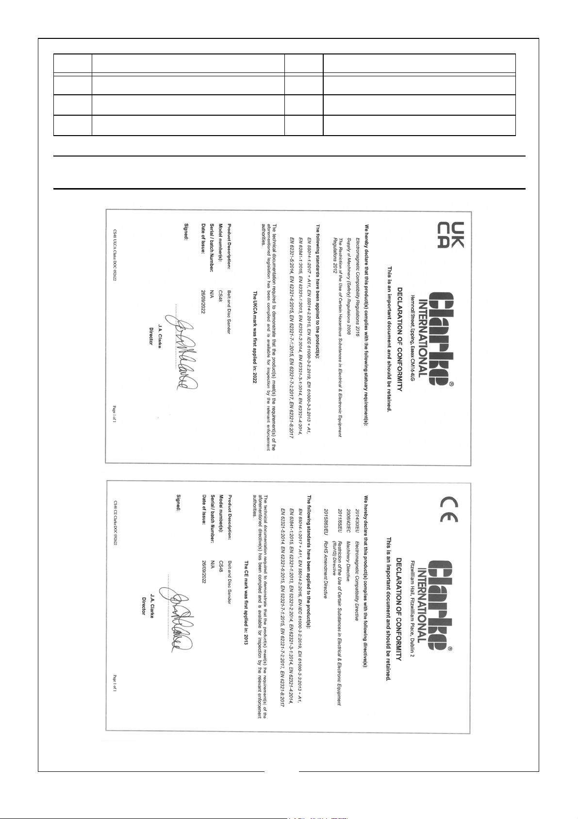
DECLARATION OF CONFORMITY
19
Parts & Service: 020 8988 7400 / E-mail: [email protected] or [email protected]
Page 20

 Loading...