

Page 1

BENCH GRINDER
MODEL Nos.
CBG6RL & CBG8RL
CBG6RSC & CBG8RSC
CBG6RWC & CBG8RWC
CBG6RR & CBG6RRW
CBG8RL
OPERATING & MAINTENANCE
INSTRUCTIONS
0108
Page 2
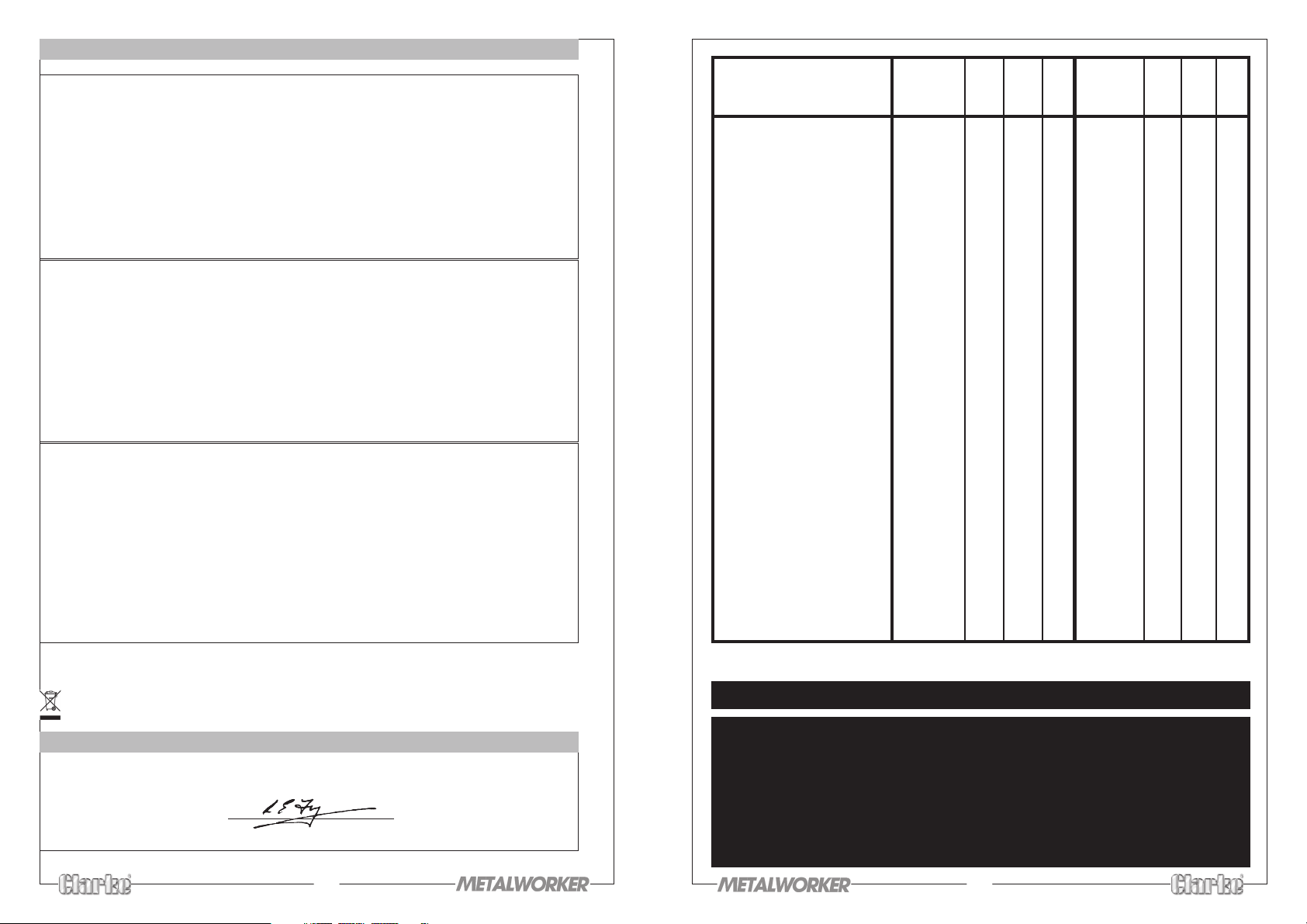
TECHNICAL DATA
CBG6RL CBG8RL
Grinding Wheel Size 2x150x20x12.7mm 2x200x20x32mm
Grade of Grinding Wheel 1 x Grit Size 36 1 x Grit Size 36
1 x Grit Size 80 1 x Grit Size 80
Power Supply 230V 50Hz 1ph 230V 50Hz 1ph
Motor size 250W 375W
Speed (RPM) 2,950 2,950
Weight-packed 12kg 16kg
Part No. 6500500 6500510
CBG6RSC & CBG6RR CBG8RSC
Grinding Wheel Size 2x150x20x12.7mm 2x200x20x32mm
Grade of Grinding Wheel 1 x Grit Size 36 1 x Grit Size 36
1 x Grit Size 80 1 x Grit Size 80
Power Supply 230V 50Hz 1ph 230V 50Hz 1ph
Motor size 250W 375W
Speed (RPM) 2,950 2,950
Weight-packed 12kg 16kg
Part No. 6500030 6500040
CBG6RWC & CBG6RRW CBG8RWC
Grinding Wheel Size 1x150x20x12.7mm 1x200x20x32mm
Grade of Grinding Wheel 1 x Grit Size 60 1 x Grit Size 60
Wire Wheel Size 1x150x20x32mm** 1x200x20x32mm
Power Supply 230V 50Hz 1ph 230V 50Hz 1ph
Motor size 250W 375W
Speed (RPM) 2,950 2,950
Weight-packed 12kg 16kg
Part No. 6500035 6500045
**Insert provided
Duty Cycle 20/20 min
Please note that the details and specifications contained herein, are correct at the time of going to print. However,
CLARKE International reserve the right to change specifications at any time without prior notice.
When disposing of this product, do not dispose of with general waste. It must be disposed of according to the laws
governing Waste Electrical and Electronic equipment, at a recognised disposal facility.
DECLARATION of CONFORMITY
We declare that this product conforms to the following directives:
• 98/37EC
signed
L.E. Fergusson
Engineering Manager
Parts List cont.
No. Description Part No. Qty Qty Qty Part No. Qty Qty Qty
34 Spring Washer HT6R034 12 12 12 HT8R034 12 12 12
35 Nut Hex HT6R035 6 6 6 HT8R035 6 6 6
36 Tool Rest Left HT6R036 1 1 1 HT8R036 1 1 1
37 Wheel Cover Inner Left HT6R037 1 1 1 HT8R037 1 1 1
38 Screw HT6R038 6 6 6 HT8R038 6 6 6
38a Spring washer HT6R038A 6 6 6 HT8R038A 6 6 6
39 Wheel Nut Left Hand HT6R039 1 1 1 HT8R039 1 1 1
40 Wheel Cover Outer Left HT6R040 1 1 1 HT8R040 1 1 1
41 Screw HT6R041 2 2 2 HT8R041 2 2 2
42 Flat Washer HT6R042 2 2 2 HT8R042 2 2 2
42a Spring Washer HT6R042A 2 2 2 HT8R042A 2 2 2
43 Screw HT6R043 2 2 2 HT8R043 2 2 2
45 Flat Washer HT6R045 4 4 4 HT8R045 4 4 4
46 Spring Washer HT6R046 2 2 2 HT8R046 2 2 2
47 Nut HT6R047 2 2 2 HT8R047 2 2 2
48 Eye Shield HT6R048 2 2 2 HT8R048 2 2 2
49 Spark Arrester Bracket HT6R049 2 2 2 HT8R049 2 2 2
50 Earth terminal HT6R050 1 1 1 HT8R050 1 1 1
51 Earth terminal screw HT6R050 2 2 2 HT8R051 1 1 1
52 Star washer HT6R052 2 2 2 HT8R052 2 2 2
53 Lampholder HT6R053 n/a n/a 1 HT8R053 n/a n/a 1
54 Sleeving HT6R054 n/a n/a 1 HT8R054 n/a n/a 1
55 Support Holder HT6R055 n/a n/a 1 HT8R055 n/a n/a 1
56 Screw HT6R056 n/a n/a 1 HT8R056 n/a n/a 1
57 Shade HT6R057 n/a n/a 1 HT8R057 n/a n/a 1
58 Nut HT6R058 n/a n/a 1 HT8R058 n/a n/a 1
59 Hose Holder HT6R059 n/a n/a 1 HT8R059 n/a n/a 1
60 Screw HT6R060 n/a n/a 1 HT8R060 n/a n/a 1
61 Sleeve HT6R061 n/a n/a 1 HT8R061 n/a n/a 1
62 Hose HT6R062 n/a n/a 1 HT8R062 n/a n/a 1
63 Bushing (threaded) HT6R063 n/a n/a 1 HT8R063 n/a n/a 1
64 Nut HT6R064 n/a n/a 1 HT8R064 n/a n/a 1
65 Power cable HT6R065 n/a n/a 1 HT8R065 n/a n/a 1
6RSC 6RWC 6RL 8RSC 8RWC 8RL
6RR 6RRW
PARTS & SERVICE CONTACTS
For Spare Parts and Service, please contact your nearest dealer,
or CLARKE International, on one of the following numbers.
PARTS & SERVICE TEL: 020 8988 7400
PARTS & SERVICE FAX: 020 8558 3622
or e-mail as follows:
PARTS: [email protected]
SERVICE: [email protected]
10
Page 3
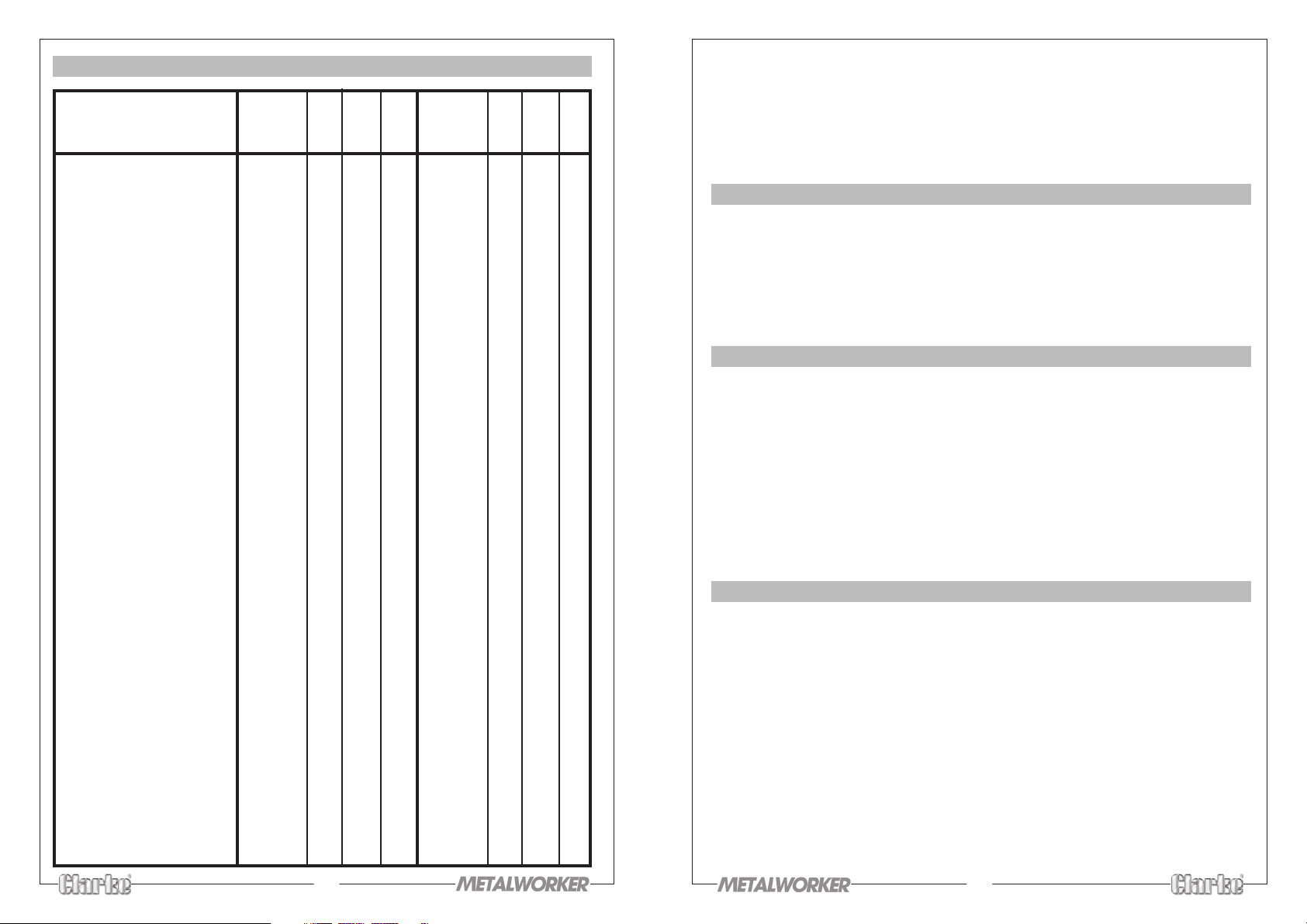
PARTS LIST
6RSC 6RWC 6RL 8RSC 8RWC 8RL
6RR 6RRW
No. Description Part No. Qty Qty Qty Part No. Qty Qty Qty
1 Case Motor HT6R001 1 1 1 HT8R001 1 1 1
2 Stator HT6R002 1 1 1 HT8R002 1 1 1
3 Rotor Shaft HT6R003 1 1 1 HT8R003 1 1 1
4 Circlip HT6R004 2 2 2 HT8R004 n/a n/a n/a
5 Bearing HT6R005 2 2 2 HT8R005 2 2 2
6 End Bell HT6R006 2 2 2 HT8R006 2 2 2
7 Base Motor HT6R007 1 1 n/a HT8R007 1 1 n/a
7A Base Motor HT6R007A n/a n/a 1 HT8R007A n/a n/a 1
8 Switch Base Plate HT6R008 1 1 1 HT8R008 1 1 1
- Switch Base Screw HT6R008A 2 2 2 HT8R008A 2 2 2
- Switch Base Star Washer HT6R008B 2 2 2 HT8R008B 2 2 2
9 Switch Assembly HT6R009 1 1 1 HT8R009 1 1 1
10 Capacitor HT6R010 1 1 1 HT8R010 1 1 1
11 Capacitor Clamp HT6R011 1 1 1 HT8R011 1 1 1
12 Cable HT6R012 1 1 1 HT8R012 1 1 1
13 Plate Securing HT6R013 1 1 1 HT8R0013 1 1 1
- Plate Securing Screw HT6R013A 2 2 2 HT8R013A 2 2 2
14 Grommet HT6R014 1 1 1 HT8R014 1 1 1
15 Grommet HT6R015 1 1 1 HT8R015 1 1 1
16 Rubber Foot HT6R016 4 4 4 HT8R016 4 4 4
17 Screw HT6R017 4 4 4 HT8R017 4 4 4
18 Bolt Hex 6mm HT6R018 2 2 2 HT8R018 2 2 2
18a Spring washer 6mm HT6R018A 2 2 2 HT8R018A 2 2 2
18b Bolt Hex 5mm HT6R018B 1 1 1 HT8R018B 1 1 1
18c Spring washer 5mm HT6R018C 1 1 1 HT8R018C 1 1 1
19 Pan Head Screw HT6R019 8 8 8 HT8R019 8 8 8
20 Flat Washer HT6R020 8 8 8 HT8R020 8 8 8
20a Spring washer HT6R020A 8 8 8 HT8R020A 8 8 8
21 Base Cover HT6R021 1 1 1 HT8R021 1 1 1
22
Wheel Cover Outer Right
23 Wheel Nut Right Hand HT6R023 1 1 1 HT8R023 1 1 1
24 Wheel Flange Outer HT6R024 2 2 2 HT8R024 2 2 2
25 Wire Wheel HT6R025 n/a 1 n/a HT8R025 n/a 1 n/a
25a G. Wheel - Coarse 6501088 1 n/a 1 6501110 1 n/a 1
25b G. Wheel - Medium 6501089 n/a 1 n/a 6501024 n/a 1 n/a
25c G. Wheel - Fine 6501135 1 n/a 1 6501130 1 n/a 1
26 Wheel Flange Inner HT6R026 2 2 2 HT8R026 2 2 2
27 Wheel Cover HT6R027 2 2 2 HT8R027 2 2 2
28 Wheel Cover Inner Right HT6R028 1 2 2 HT8R028 1 1 1
29 Tool Rest Right Hand HT6R029 1 1 1 HT8R029 1 1 1
30 Flat Washer HT6R030 4 4 4 HT8R030 4 4 4
30a Spring washer HT6R030A 4 4 4 HT8R030A 4 4 4
31 Screw Hex HT6R031 4 4 4 HT8E031 4 4 4
32 Bolt HT6R032 6 6 6 HT8R032 6 6 6
33 Flat Washer HT6R033 12 12 12 HTR033 12 12 12
HT6R022 1 1 1 HT8R022 1 1 1
9
Thank you for purchasing this CLARKE BENCH GRINDER, which is designed for DIY
and general workshop use.
Before attempting to operate this machine, please read this instruction manual
thoroughly and follow all directions carefully. By doing so you will ensure the safety
of both yourself and others around you, and at the same time, you should look
forward to long and trouble free service from your Bench Grinder.
GUARANTEE
This product is guaranteed against faults in manufacture for 12 months from
purchase date. Keep your receipt as proof of purchase. This guarantee is invalid
if the product has been found to have been abused in any way, or not used for the
purpose for which it was intended, or to have been tampered with in any way. The
reason for return must be clearly stated. This guarantee does not affect your
statutory rights.
CONTENTS PAGE
Guarantee, General Safety Rules ................................................... 2
Special Safety Rules for Grinders ..................................................... 3
Electrical Connections, Fuse Rating ............................................... 4
Pre Assembly Check / Assembly ..................................................... 5
Maintenance - Adjustments / Changing the Grinding Wheel..... 6
Parts List and Diagram ...................................................................... 8 - 10
Technical Data .................................................................................. 11
Parts and Service .............................................................................. 11
GENERAL SAFETY RULES
1. KEEP GUARDS IN PLACE and check they are not damaged.
2. REMOVE ADJUSTING KEYS AND WRENCHES. Make a habit of checking to see
that all adjusting keys and wrenches are removed from machine before
turning it on.
3. KEEP WORK AREA CLEAN. Cluttered areas and work benches invite accidents
4. DO NOT USE IN A DANGEROUS ENVIRONMENT. Do not use any power tools
in damp or wet areas, or expose them to rain. Keep work area well lit.
5. KEEP CHILDREN AWAY. All visitors, but in particular children, should be kept at
a safe distance away from the work area.
6. MAKE YOUR WORKSHOP CHILDPROOF with padlocks, master switches, or by
removing starter keys.
7. DO NOT FORCE YOUR BENCH GRINDER. It will do a better and safer job if used
at the rate for which it was designed.
2
Page 4
8. WEAR THE PROPER APPAREL. No loose clothing, gloves, neckties, rings,
bracelets, or any other jewellery which might get caught in moving parts.
Non-slip footwear is recommended. Long hair should be contained.
9. ALWAYS USE SAFETY GLASSES. Everyday glasses only have impact resistant
lenses, they are not safety glasses. Also use a face mask if a lot of dust is
generated.
10. DO NOT OVERREACH. Keep a firm footing and proper balance at all times.
11. DISCONNECT FROM THE MAINS before attempting any kind of service work or
adjustment or when changing accessories such as grinding wheels.
12. MAINTAIN TOOLS WITH CARE. Keep tools sharp and clean for best and safest
performance.
13. REDUCE THE RISK OF UNINTENTIONAL STARTING. Make sure switch is in the OFF
position before plugging in.
14. CHECK FOR DAMAGED PARTS. Before using the machine, always check parts
for signs of damage, and to ensure they are secure. If a component suffers
slight damage, (eg. a distorted guard or bracket), make sure it will perform its
intended function properly before switching on. If in doubt, do not use the
machine. ALWAYS be prepared to SWITCH OFF IMMEDIATELY, if you
experience unusual noises, or excessive vibration. Do not use the machine
until the fault is fully rectified.
ADDITIONAL SAFETY RULES FOR BENCH GRINDERS
1. Replace a cracked wheel immediately.
2. Always use guards and eye shield
3. Do not overtighten wheel nut.
4. Maintain the distance between wheel and tool rest to 1/16 (1.6mm) or less as
the diameter of the wheel decreases with use.
5. Use a grinding wheel suitable for the speed of grinder. (See technical data).
6. Stand to one side of bench grinder during operation, not directly in front.
7. One minute of free rotation is necessary for a new grinding wheel. Should the
new grinding wheel be faulty and break, it will happen within the first minute
of operation.
8. Do not remove the wheel guard except when changing a worn wheel.
9. Do not use the grinding wheel for any kind of cutting.
10. Do not use the side of the wheel for any reason.
11. Do not over stress the grinding wheel.
12. NEVER leave a grinder running unattended. Turn power off. Do not leave tool
until it comes to a complete stop.
13. Use ONLY approved replacement grinding wheels. Contact your local dealer
for approved replacement grinding wheels. The use of inferior parts may risk
of injury.
3
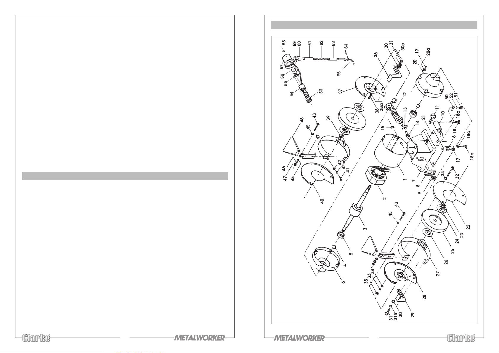
PARTS DIAGRAM
8
Page 5

brackets from time to time. Adjustments can be made by loosening the mounting
screw, and positioning the bracket accordingly, remembering to re-tighten the
screw once adjustment is complete.
The see-through Eye Shields allow the user to see the operation clearly, and to work
precisely. The eye shields can be adjusted on their pivots to suit the operator.
IMPORTANT: Even though Eye Shields are fitted, you should nevertheless, ALWAYS
wear safety goggles when operating a grinding machine.
B. TOOL REST ADJUSTMENT
The appropriate adjustment of the tool rests provides the operator with a correct
working angle and a firm and efficient base for working. A gap of approx. 1/16"
between the wheel and tool rest should be maintained at all times. Due to wear on
the grinding wheel, it is necessary to adjust the tool rests from time to time.
Adjustments can be made by loosening the mounting screws, and positioning the
tool rest accordingly, remembering to re-tighten the screws once adjustment is
complete.
C. CHANGING THE GRINDING / WIRE WHEEL
1. Remove outside wheel cover, by unscrewing the cover retaining bolts, and
slacken the Tool Rest and Spark Arrester mounting screws.
2. Holding the wheel firmly, remove the nut and flange using the correct size
spanner, noting that the left wheel nut carries a left hand thread.
IMPORTANT: Always wear a heavy duty glove to hold a wire wheel.
3. Take off the used wheel and replace with a new one, ensuring the blotter is in
place between the wheel and flange. Do not overtighten the nut - holding
the wheel with your hand will enable you to apply sufficient force to tighten
the nut effectively.
4. Re-assemble, steps A & B as detailed above, ensuring that there is a good
balanced rotation of the wheel.
5. Switch on the machine and allow the wheel to rotate freely, for at least 1
minute.
D. DRESSING THE WHEEL
It will be necessary from time to time to dress the wheel, to obtain a true working
surface. This should be done ONLY with an approved dressing tool, which can be
obtained from your CLARKE dealer, quoting Model Number GWD-1. Part No.
6501120.
ELECTRICAL CONNECTIONS
Connect the mains lead to a standard, 230 volt (50Hz) electrical supply through a
fused good quality 13 amp BS 1363 plug, or a suitable fused isolator switch.
WARNING: THIS APPLIANCE MUST BE EARTHED
IMPORTANT: The wires in the mains lead are coloured in accordance with the
following code:
Green & Yellow —- Earth
Blue —- Neutral
Brown —- Live
As the colours of the flexible cord of this appliance may not correspond with the
coloured markings identifying terminals in your plug, proceed as follows:
Connect GREEN & YELLOW cord to terminal marked with a letter “E” or Earth
symbol ‘ ’ or coloured GREEN or GREEN & YELLOW.
Connect BROWN cord to terminal marked letter “L” or coloured RED.
Connect BLUE cord to terminal marked letter “N” or coloured BLACK.
We recommend that this unit is fitted with a Residual Current Device (RCD).
FUSE RATING
The fuse in the plug for this appliance must be rated at 5 amps
IMPORTANT NOTICE
If this appliance is fitted with a plug which is moulded on to the electric cable (i.e.
non rewirable) please note:
1. This plug must be thrown away if it is cut from the electric cable. There is a
danger of electric shock if it is subsequently inserted in a socket outlet.
2. Never use the plug without the fuse cover fitted.
3. Should you wish to replace a detachable fuse carrier, ensure that the correct
re-placement is used (as indicated by marking or colour code).
4. Replacement fuse covers can be obtained from your local dealer, or an
electrical stockist.
5. The fuse in the plug must be 5 Amps, and any replacement must be ASTA
approved to BS1362.
E. OPERATING THE LAMP (CBG6RL and CBG8RL only)
The lamp is provided with a rotary type switch located at the rear of the lamp
7
4
Page 6
PRE-ASSEMBLY CHECK
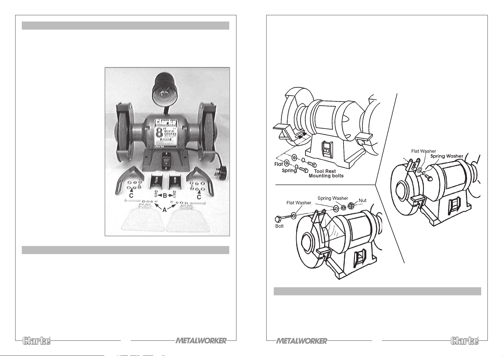
Before assembling your Bench Grinder, please check to ensure that all the parts
listed below have been included. If any parts are missing or damaged, you should
immediately contact your local dealer or CLARKE International on 0181-558 6696
for replacement.
1. Main Body (switch and
power cable with plug are
included. Additionally, the
CBG6RL and 8RL models
include a lamp assembly
complete with bulb).
2. Two Eyeshields, each
complete with 1 x nut, 1 x
bolt, 1 x spring washer and
2 x flat washers (A).
3. Two spark arrestor
brackets, each complete
with 1 x screw, 1 x spring
washer and 1 x flat washer
(B).
4. Two Tool rests, each
complete with 2 x screws,
2 x spring washers and 2 x
flat washers (C).
rotation. As the wheel wears down with use, it will be necessary to re-adjust
the brackets accordingly.
3. Assemble the Eye Shields on to the Spark Arrester Brackets using the nuts, bolts
and washers supplied, in the manner shown in fig. 3. The angle of the Eye
Shields are adjustable to suit the operator.
4. Your Clarke Bench Grinder should be securely bolted to a workbench before
operation, using the pre-drilled holes in the base.
2 x 5/16" (8mm) bolts are recommended. (Not supplied)
Fig. 1
Fig. 2
Fig. 3
ASSEMBLY
1. Attach the tool rests with the bolts and washers provided, in the manner
shown in fig 1 - page 6.
The tool rests are adjustable and should be positioned 1/16" (1.6mm) from the
grinding wheels, ensuring they are firmly fixed and horizontal.
NOTE: Tool rests are not used with the Wire Wheels fitted to the CBG6RWC and
8RWC models, but are available as an accessory. (See your CLARKE dealer).
2. Assemble the Spark Arrester Brackets on to the Wheel Guards, using the single
screw and washers provided, in the manner shown in fig. 2 - page 6.
NOTE: Before fully tightening the screw, each bracket should be adjusted by
sliding it as close as possible to the grinding wheel without impairing the
wheel
s
5
MAINTENANCE
Before carrying out any service or adjustments, ensure the grinder is switched OFF,
and disconnected from the electrical supply.
A. SPARK ARRESTER & EYE SHIELD ADJUSTMENT
Due to wear on the grinding wheel, it is necessary to adjust the Spark Arrester
6
 Loading...