

Page 1
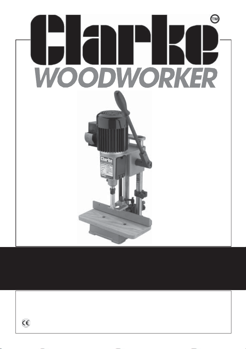
MORTISING MACHINE
Model No. CBM 2B
Part No. 6500005
OPERATING & MAINTENANCE
INSTRUCTIONS
0202
Page 2

PARTS & SERVICE
PARTS & SERVICE TEL: 020 8988 7400
or e-mail as follows:
PARTS: [email protected]
SERVICE: [email protected]
© Copyright CLARKE International. All rights reserved. February,2002
2
Page 3

Thank you for selecting this CLARKE CBM2B Bench Mortising Machine.
Before operating the machine, please read this leaflet thoroughly and follow the
instructions carefully. In doing so you will ensure the safety of yourself and that of
others around you, and you can look forward to the machine giving you long and
satisfactory service.
GUARANTEE
This CLARKE product is guaranteed against faulty manufacture for a period of 12
months from the date of purchase. Please keep your receipt as proof of purchase.
This guarantee is invalid if the product is found to have been abused or tampered
with in any way, or not used for the purpose for which it was intended.
Faulty goods should be returned to their place of purchase, no product can be
returned to us without prior permission.
This guarantee does not effect your statutory rights.
CONTENTS Page
Safety Precautions .................................................................................. 4
Additional precautions for Mortising Machines ................................... 5
Electrical Connections ........................................................................... 6
Unpacking & Principal Parts ................................................................... 7
Assembly.................................................................................................. 8
Mounting the Chisel & Bit ....................................................................... 10
Installation ................................................................................................ 12
Controls and Adjustments ...................................................................... 12
Operation ................................................................................................. 14
Maintenance ........................................................................................... 15
Sharpening Drill Bit & Chisel ................................................................... 16
Parts List & Diagram................................................................................. 17
Accessories.............................................................................................. 18
Specifications .......................................................................................... 18
3
Page 4

SAFETY PRECAUTIONS
GENERAL SAFETY RULES FOR OPERATING MACHINERY
WARNING:
As with all machinery, there are certain hazards involved with their operation and
use. Exercising respect and caution will considerably lessen the risk of personal
injury. However, if normal safety precautions are overlooked or ignored, personal
injury to the operator or damage to property, may result.
1. READ and BECOME FAMILIAR with the entire operating manual. Learn the
machines’ applications and limitations as well as the specific potential hazards
peculiar to it.
2. EARTH ALL MACHINES. If the machine is equipped with three-pin plug, it should
be plugged into a three-pin electrical socket. Never remove the earth pin.
3. ALWAYS ensure that ADEQUATE LIGHTING is available. A minimum intensity of
300 lux should be provided. Ensure that lighting is placed so that you will not
be working in your own shadow.
4. CHECK for DAMAGE. Before using the machine, any damaged part, such as
a guard etc., should be checked to ensure that it will operate properly, and
perform its intended function. Check for alignment of moving parts, breakage
of parts, mountings, and any other condition that may affect the machines’
operation. Any damage should be properly repaired or the part replaced. If
in doubt, DO NOT USE the machine. Consult your local dealer.
5. DISCONNECT the MACHINE from the power supply before servicing and when
changing accessories or performing maintenance tasks.
6. KEEP GUARDS in place and in working order.
7. ALWAYS WEAR SAFETY GOGGLES, manufactured to the latest European Safety
Standards. Also use face or dust mask if cutting operation is dusty. Everyday
eyeglasses do not have impact resistant lenses, they are NOT safety glasses.
8. KEEP WORK AREA CLEAN. Cluttered areas and benches invite accidents.
9. DON’T FORCE the Machine. It will do a better and safer job at the rate for
which it was designed.
10. REMOVE ADJUSTING KEYS AND WRENCHES. Form the habit of checking to see that
keys and adjusting wrenches are removed from the machine beforeswitching on.
11. DRUGS, ALCOHOL, MEDICATION. Do not operate machine whilst under the
influence of drugs, alcohol or any medication.
12. USE RECOMMENDED ACCESSORIES. The use of improper accessories could
be hazardous.
13. NEVER LEAVE MACHINE RUNNING UNATTENDED. Turn power OFF. Do not leave
machine until it comes to a complete stop.
4
Page 5

14. KEEP CHILDREN AWAY. All visitors should be kept a safe distance from the work
area, especially whilst operating the unit.
15. MAINTAIN MACHINE IN TOP CONDITION. Keep tools sharp and clean for the
best and safest performance. Follow maintenance instructions.
16. DON’T OVERREACH. Keep your proper footing and balance at all times. For best
footing, wear rubber soled footwear. Keep floor clear of oil, scrap wood, etc.
17. WEAR PROPER APPAREL. Loose clothing or jewellery may get caught in moving
parts. Wear protective hair covering to contain long hair.
18. BE AWARE that accidents are caused by carelessness due to familiarity. ALWAYS
concentrate on the job in hand, no matter how trivial it may seem.
ADDITIONAL SAFETY INSTRUCTIONS for MORTISING ACHINES
1. DO NOT USE until unit is completely assembled and installed according to
these instructions.
2. IF YOU ARE NOT thoroughly familiar with the operation of mortising machines,
obtain advice from a qualified person.
3. ENSURE the machine is secured to a workbench to prevent it from tipping
over during operation.
4. NEVER TURN MORTISING MACHINE ON before clearing the table of all objects
(tools, scrap pieces, etc.).
5. ALWAYS KEEP hands, fingers and hair well away from the rotating bit.
6. DO NOT ATTEMPT to mortise materials that do not have a flat surface, unless a
suitable support is used.
7. ALWAYS use the ‘Hold Down’ to prevent work from lifting when withdrawing
the chisel.
8. ALWAYS SUPPORT workpiece securely against fence to prevent rotation.
9. ENSURE chisel and bit is sharp, undamaged and properly secured before use.
10. ENSURE the chuck key is removed before starting.
11. NEVER START the Machine with the drill bit or chisel pressed against the
workpiece.
12. NEVER PERFORM LAYOUT, assembly or set-up work on the Machine with the
cutting tool rotating.
13. ALWAYS ADJUST DEPTH STOP to avoid drilling into the table.
14. ALWAYS STOP the machine before removing scrap pieces from the table.
15. SHUT OFF POWER, remove the drill bit and chisel and clean the table before
leaving the machine.
16. NEVER PLACE YOUR FINGERS in a position where the drill or cutting tool could
contact them if the workpiece should shift unexpectedly.
5
Page 6

ELECTRICAL CONNECTIONS
Connect the mains lead to a standard, 230 Volt (50Hz) electrical supply through
an approved 13 amp BS 1363 plug, or a suitably fused isolator switch.
WARNING! THIS APPLIANCE MUST BE EARTHED
IMPORTANT: The wires in the mains lead are coloured in accordance with the
following code
Green & Yellow ........................ Earth
Blue ............................................ Neutral
Brown ........................................ Live
As the colours of the flexible lead of this appliance may not correspond with the
coloured markings identifying terminals in your plug proceed as follows:
• Connect GREEN & YELLOW coloured cord to plug terminal marked with a
letter “E” or Earth symbol “ ” or coloured GREEN or GREEN & YELLOW.
• Connect BROWN coloured cord to plug terminal marked with a letter “L” or
coloured RED.
• Connect BLUE coloured cord to plug terminal marked with a letter “N” or
coloured BLACK.
If this appliance is fitted with a plug which is moulded onto the electric cable (i.e.
non-rewirable) please note:
1. The plug must be thrown away if it is cut from the electric cable. There is a
danger of electric shock if it is subsequently inserted into a socket outlet.
2. Never use the plug without the fuse cover fitted.
3. Should you wish to replace a detachable fuse carrier, ensure that the correct
replacement is used (as indicated by marking or colour code).
Fuse Rating
The fuse in the plug must be replaced with one of the same rating (13 amps) and
this replacement must be ASTA approved to BS1362.
Important: If a cable extension is needed, it is essential to comply with the following
data.
Extension length Cable section
Up to 20m ....................................... 2.5mm
From 20 to 50m ..............................4mm
6
2
2
Page 7
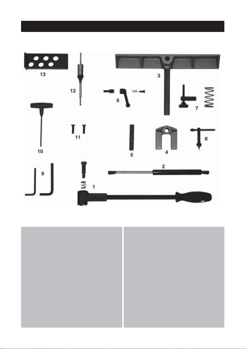
UNPACKING
Unpack the shipping carton, and lay out the components so that they can be
clearly identified. Check them off as follows:
Should there be any deficiency or damage to any of the components, please
contact your Clarke dealer immediately
1. Operating Handle c/w pin & spring
2. Damper
3. Fence
4. Hold Down
5. Hold Down Post
6. Fence Locking Lever, comprising
6.1 Lever
6.2 Screw post
6.3 Screw
6.4 Spring
7. Fence Adjuster c/w Spring
8. Chuck Key
9. 2 x Hex. Wrenches - 6mm & 8mm
10. Hex. Key 4mm
11. 2 x C’sk Head Screws
12. 1/2” Mortice and Bit
13. Wall Bracket for Mortice and Bits
Not Shown
1. Table
2. Mortice Machine
complete with 13mm Chuck.
7
Page 8
ASSEMBLY.
WARNING:
For your own safety, do not connect the Mortising Machine to a power
source until it is fully assembled, and you have read and understood all
safety and operational instructions.
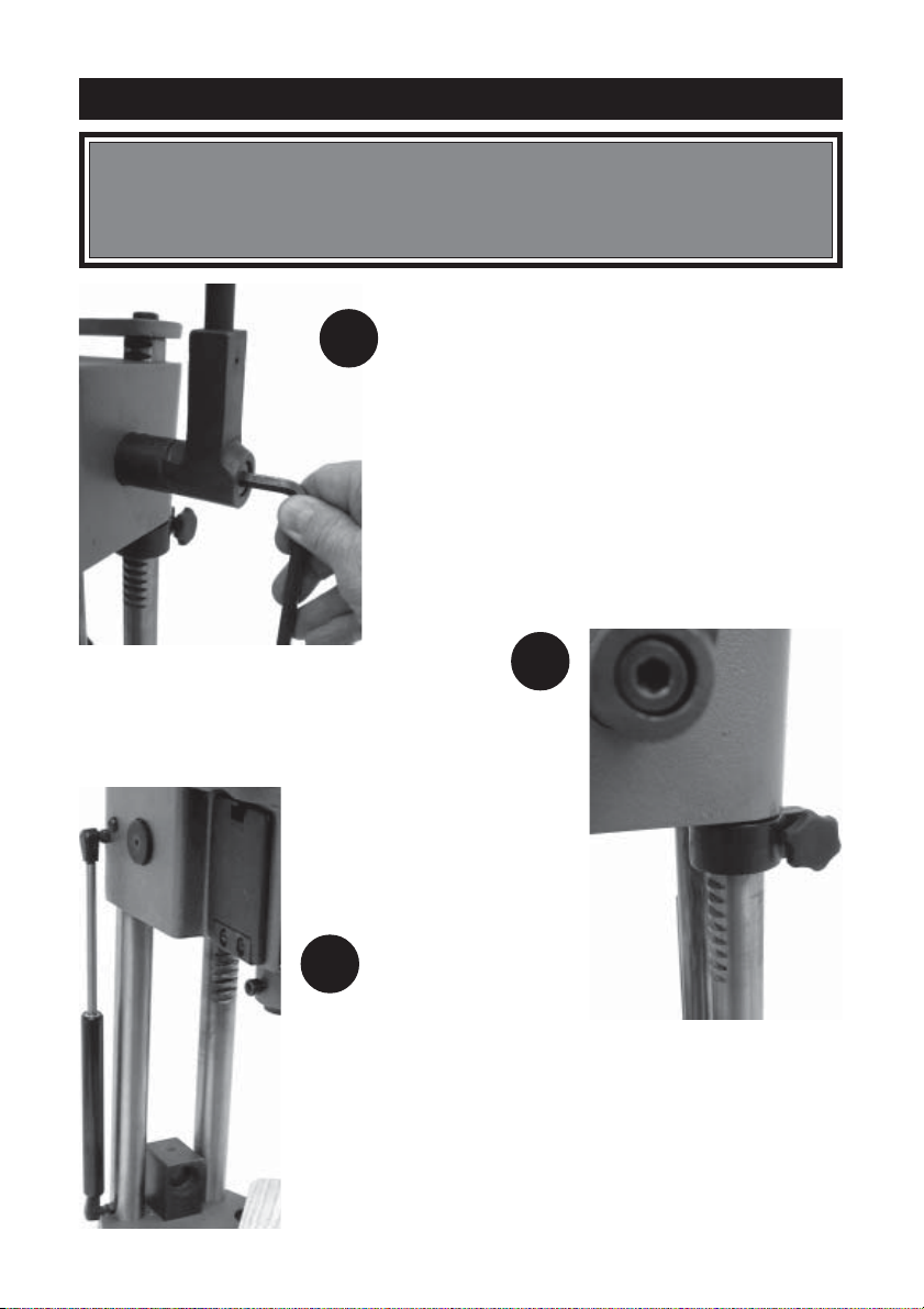
1. Secure the Operating Handle by screwing
1
the pin with spring into the hole in the
pinion shaft. Tighten using the Hex. wrench
provided
NOTE:
The handle is used to raise and lower the head. It
may be adjusted for maximum leverage and
comfort during operation. To do this, pull the lever
away from the shaft and turn it to a more
comfortable or appropriate position. Release the
lever and it will return under spring pressure.
2
2. Raise the head using
the Operating handle
to the top of its travel,
and hold in place by
securing the Depth
Stop.
3
3. Attach the Damper to its two
fittings by pushing it on the
spherical housings until they
click into place.
8
Page 9
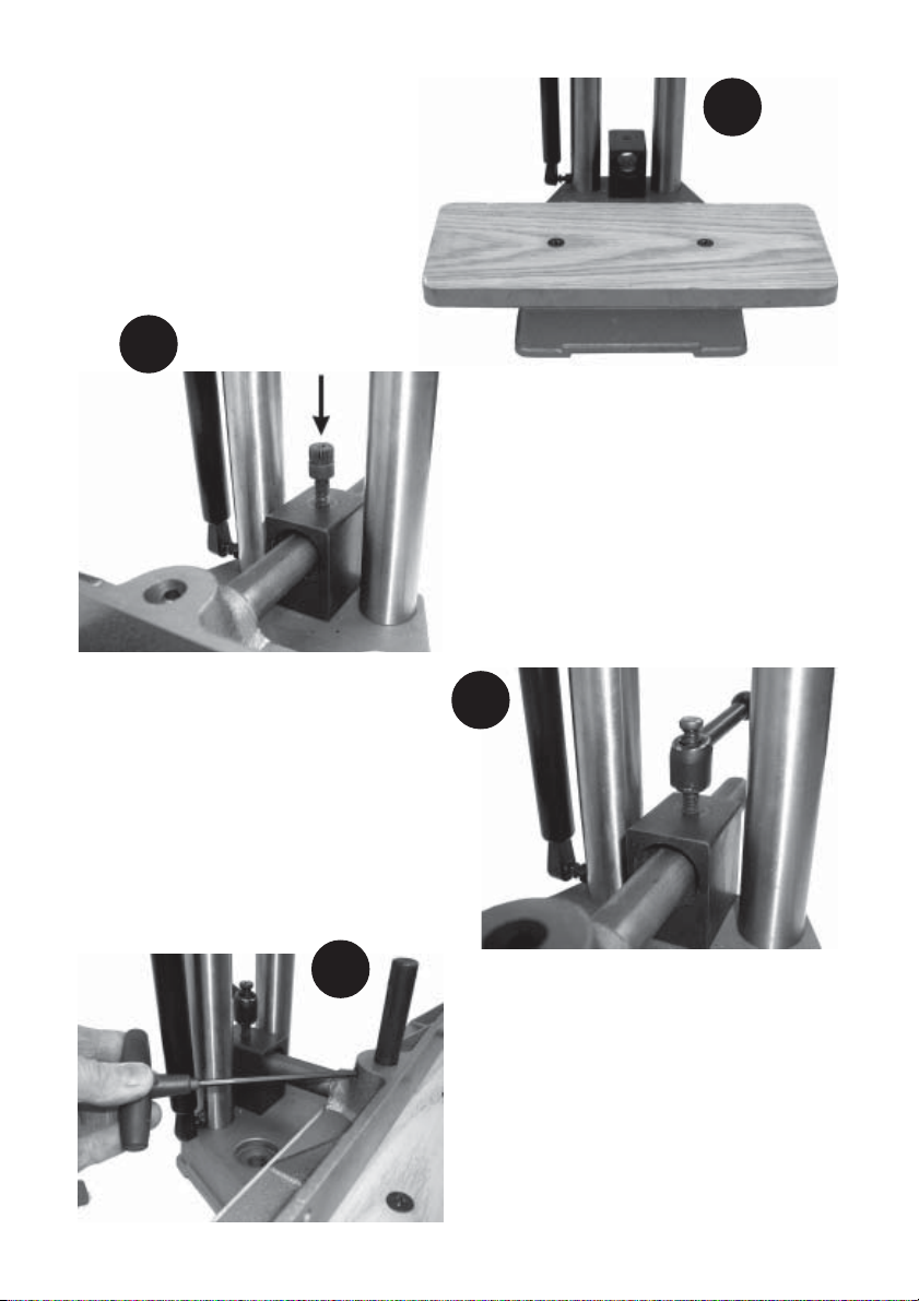
4. Assemble the Table to the base
using the two countersunk
headed screws provided.
5
4
5. Insert the stem of the Fence
assembly through the hole in
the block and secure with
the Fence Locking Lever.
First screw the post into the
housing.....
5A
5A....then attach the Locking
Lever and secure with
the screw and spring.
6
9
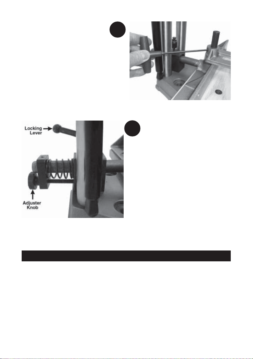
6. Insert the Hold Down Post into the
hole in the fence, with the flat
facing the grub screw in the
fence housing.
Secure with the grub screw, using
the Hex. Key provided.
Page 10
7
7. Lower the Hold Down on to the
post, and secure temporarily, by
tightening the grub screw.
8
8. Slacken the Fence Locking Lever
then push the Fence IN fully so that
the Fence Adjuster may be
positioned on the Fence stem as
shown.
Secure using the grub screw
provided
INSTALLATION
IMPORTANT:
Before using the machine,it must be bolted down to a firm and stable workbench to
prevent it from tipping during operation. Two holes are supplied in the base for this purpose.
Additionally, the chisel and bit must be installed, and various adjustments made before
the machine can be used. These procedures are described on the following pages.
10
Page 11
PREPARING FOR USE
WARNING:
Make sure the machine is disconnected from the mains supply before
performing checks, adjustments, or setup procedures.
INSTALLING CHISEL AND BIT
CAUTION!
The chisel and drill bit are extremely sharp...take care when handling!
9
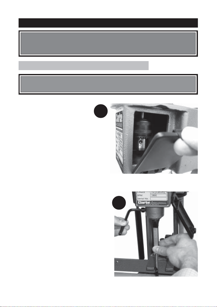
9. Open the cover...at either side, by
pulling down on the plastic
catch,to expose the chuck.
10. Insert the drill bit into the chisel then
insert the chisel and bit up through
the hole in the head.
Push the chisel up as far as possible
into the head, and nip up the grub
screw to temporarily hold it in this
position, using the hex. wrench
provided.
You can lower the drill bit gently, and
allow it to rest on the table whilst
carrying out this operation.
NOTE:
The opening in the side of the chisel
should always be to the right or left,
never to the front or rear. The opening
allows chips to escape during
operation. See ‘Adjusting Chisel
Parallel to Workpiece’ on page13.
10
11
Page 12
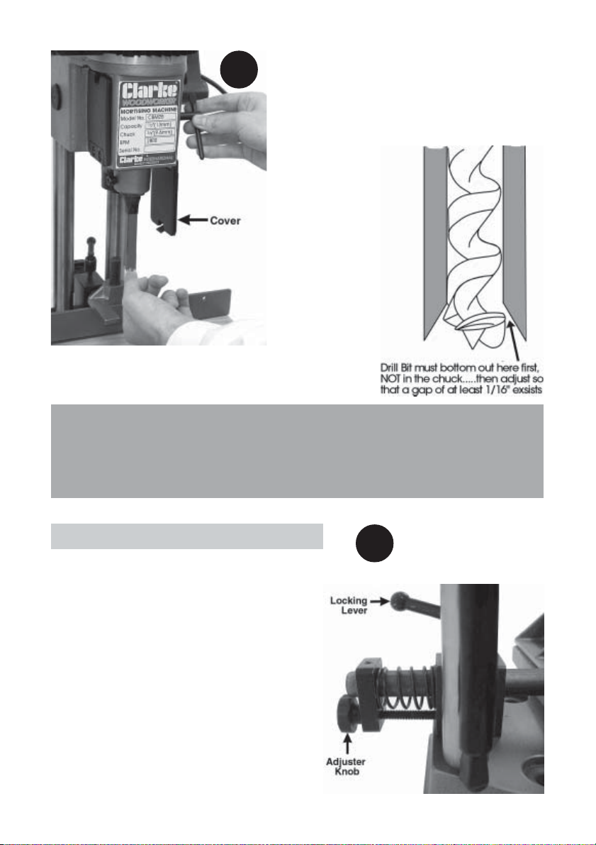
11. Push the drill bit up through chisel, and into
11
Alternatively, grind off a portion of the drill shank.
This adjustment is IMPORTANT, to ensure a proper clearance is provided between
the cutting tips of the bit and the points of the chisel.
For certain types of wood, it may be necessary to increase this distance up to
a maximum of 3/16" (5mm). This will become obvious when cutting
commences and chips are not being ejected satisfactorily.
the opened jaws of the chuck as far as it will
go, then back off approx. 1/16”(2mm).
Secure the drill bit in this position, by tightening
the jaws using the chuck key provided.
Note:
It is important that the
drill bit bottoms out on
the CHISEL and NOT
the chuck, before
setting the 1/16”
(2mm) clearance.
If the bit does bottom
out in the chuck first,
slacken off the grub
screw securing the
chisel and lower it
approx 1/16” (2mm)
and try again.
ADJUSTING THE FENCE
The fence can be moved in or out, by slackening
the locking lever, sliding the fence to the desired
position and re-tightening the locking lever.
Alternatively, precise control is possible by using
the device shown in the illustration opposite.
Slacken the fence locking lever, then screw the
adjuster in or out as required. The fence will move
accordingly.
When the workpiece, being held to the fence, is
lined up as required, tighten the Locking Lever.
The adjuster assembly may be positioned
anywhere on the stem of the fence to provide
adequate adjustment, depending upon how far
IN or OUT the fence is required to be.
12
12
Page 13
ADJUSTING CHISEL PARALLEL TO WORKPIECE
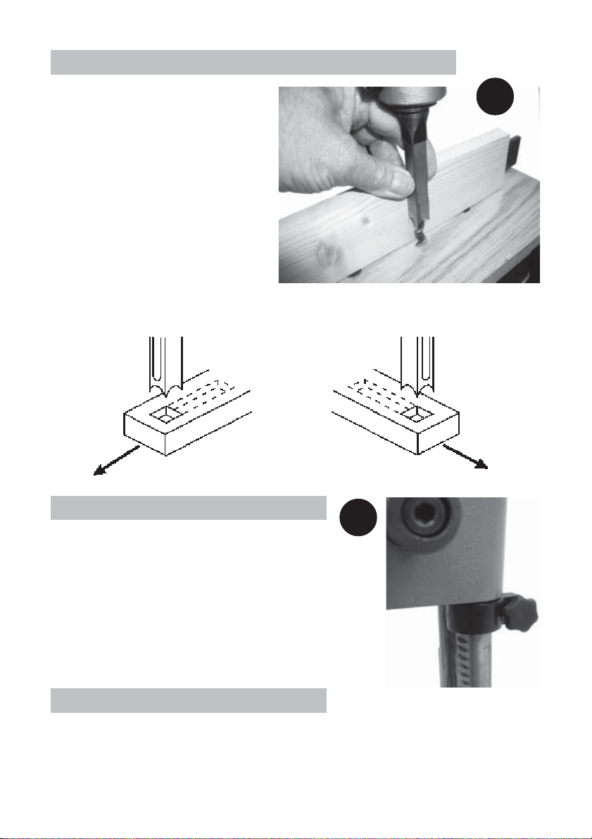
It is important that the chisel is
square to the workpiece. To
achieve this, slacken the chisel
securing screw and rotating the
chisel until the back surface is flat
against the workpiece, or a piece
of wood with parallel sides, resting
against the fence, then re-tighten
the screw, ensuring a distance of
at least 1/16” (2mm) is maintained
between the chisel and the end of
the drill bit.
It is also IMPORTANT to remember
that the slot in the side of the chisel
should always face TOWARDS THE DIRECTION OF MOVEMENT OF THE WORKPIECE
(see diagram below).
Chisel slot
on left
Move timber in
this direction
13
Chisel slot
on right
Move timber in
this direction
ADJUSTING THE DEPTH STOP
14
A depth stop is provided which may be used to limit
the depth of the chisel cut.
To adjust the depth stop, slacken the securing knob
so that the stop is capable of being moved, but will
not drop under its own weight, then raise the stop so
that it contacts the underside of the head.
Lower the head to the maximum depth desired, then
tighten the stop securing knob.
ADJUSTING THE HOLD DOWN
The purpose of the ‘Hold Down’ in to prevent the workpiece from lifting as the
chisel is raised up, out of the hole.
The hold down should be adjusted so it just touches the top of the workpiece and
allows the workpiece to slide left or right. Packing pieces may be used if necessary.
13
Page 14

OPERATION
1. Set the fence to suit the position of the mortise on the workpiece. Make sure
the fence and chisel are square to each other (see p13), and tighten in place.
Make any fine adjustments to the fence, to move the workpiece in or out, by
using the adjuster at the rear of the fence (see p12).
3. Set the depth stop to the required depth of cut as described on page 13.
4. Ensure the Hold Down rests gently on the surface of the workpiece, but not so
tight as it prevents the workpiece from moving, and lock into position. If
necessary, use packing pieces between the workpiece and the hold down
When working on long workpieces, support the timber along its length.
5. Ensure the workpiece is held firmly against the fence.
Switching ON and OFF
6. The ON-OFF switch is located on the motor. Raise the Red cover marked OFF,
and push the GREEN button to switch the machine ON.
Push the RED button or the Red cover to switch the machine OFF.
NOTE:
The switch is a No Volt Release type. If the supply is interrupted, the ON/OFF switch
will automatically revert to the OFF position. This is a safety device to prevent the
machine from starting again, should the supply be restored.
7. With the machine running, feed the chisel and bit steadily into the workpiece
by pulling down on the operating handle.
NOTES:
• It is recommended that you check the position, and depth of cut, on a piece
of scrap before cutting your workpiece.
• The rate of penetration of the chisel must be fast enough to prevent burning at the
tip of the bit, but not so fast as to cause the machine to slow or stall. With experience
you will find suitable feed rates to suit various types of timber.
• You may encounter smoke from the bit or material once the chisel has engaged
the material. The smoke created is a natural operating occurrence in hollow chisel
mortising and is caused by material chip friction and the resins in the stock being
burned off. Bluing of the chisel after initial use is not indicative of a dull chisel, but a
combination of friction and resin buildup on the cutting faces of the chisel.
• A dull chisel can be detected by the amount of excess force required to
complete a cut.
• After the first cut, the workpiece must be moved along in the correct direction
relative to the slot in the chisel, to allow chips to clear freely. Move the workpiece
so that the chisel slot is releasing chips into the already cut part of the mortise.
14
Page 15
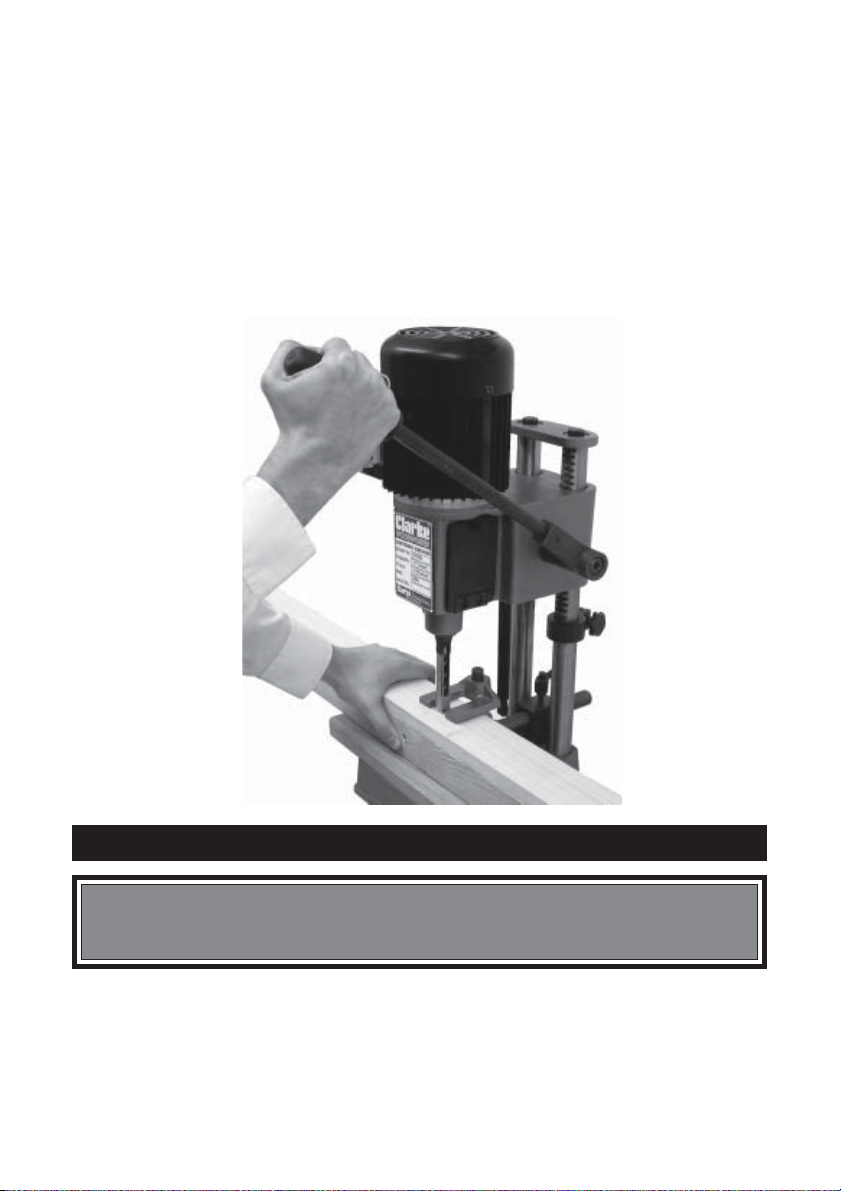
• Do not have the slot against the blind end of the mortise, as the chips will
not be able to clear from the chisel. This will cause overheating and possible
breakage to the chisel or bit.
• When cutting deep mortises, make the cut in several stages of approximately
25mm each, to allow chips to clear.
• When performing a through mortise, a piece of wood should be placed between
the workpiece and the table. This prevents the wood from splintering when breaking
through the bottom of the mortise and also prevents damage to the table.
• Always switch the mortising machine off after use. Never leave the machine
running unattended.
MAINTENANCE
WARNING:
For your own safety, turn OFF power and disconnect tool from power
source before performing any maintenance.
The machine is maintenance free except for periodically cleaning away any dust
accumulation and the application a light coat of oil to all non- painted surfaces,
particularly the two columns.
All of the bearings are packed with grease at the factory and require no further
lubrication.
15
Page 16
SHARPENING THE DRILL BIT & CHISEL
For best performance the chisel and bit need to be kept sharp. Blunt cutting
edges will give untidy and inaccurate mortises, and can cause overheating
and breaking of the chisel and bit.
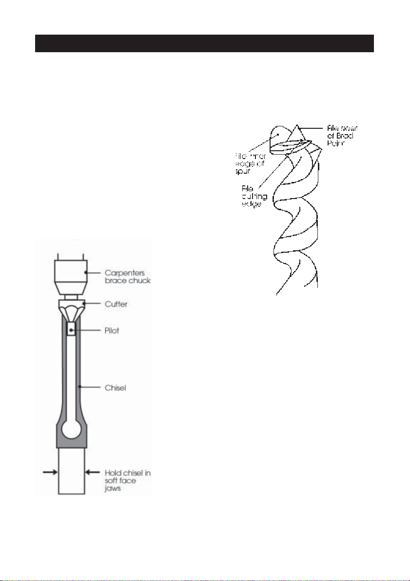
Sharpen the bit by using a small smooth
file, following the original shape of the
bit. File the inside edge of the spur, the
sides of the brad point, and the cutting
edge inwards towards the flutes of the
bit to restore sharpness. Do not file the
outside edge of the spur as this will
affect the diameter of the bit.
Use a mortice chisel cutter with the correct size
pilot to sharpen the chisel. Two or three turns of
the cutter in a carpenters hand brace should be
enough to sharpen the chisel. Remove any burrs
from the outside of the chisel with a fine oilstone.
Chisels and bits will need replacing when they
become badly worn and difficult to sharpen.
16
Page 17
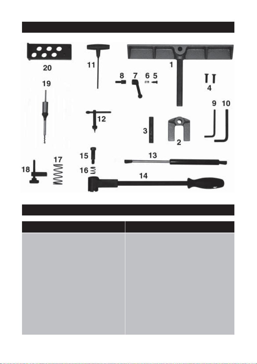
SPARE PARTS
PARTS LIST
No. Description Qty Part No.
1 Fence 1 EFCBM2B01
2 Hold Down 1 EFCBM2B02
3 Hold Down Post 1 EFCBM2B03
4 C’sk Hd. Screw 2 EFCBM2B04
5 Screw 1 EFCBM2B05
6 Spring 1 EFCBM2B06
7 Locking Lever 1 EFCBM2B07
8 Screw Post 1 EFCBM2B08
9 Hex. Wrench 6mm 1 6502089
10 Hex. Wrench 8mm 1 6502091
No. Description Qty Part No.
11 Hex. Key 4mm 1 EFCBM2B11
12 Chuck Key 1 EFCBM2B12
13 Damper 1 EFCBM2B13
14 Operating Lever 1 EFCBM2B14
15 Pin 1 EFCBM2B15
16 Spring 1 EFCBM2B16
17 Spring 1 EFCBM2B17
18 Adjuster Assembly 1 EFCBM2B18
19 Drill & Chisel set 1/4” 1 see Accesssories
20 Wall Bracket 1 EFCBM2B20
17
Page 18

ACCESSORIES
The following Morticing Chisels and Bits are available from your CLARKE dealer.
Mortice Width Bit Shank Size Part No.
1. 6mm (1/4”) ................... 5mm .................................. 6500025
2. 9mm (3/8”) ................... 6mm .................................. 6500026
3. 13mm (1/2”).................. 9mm .................................. 6500027
4. 16mm (5/8”)................. 13mm ................................. 6500028
SPECIFICATIONS
Motor ................................................................. 230VAC 50Hz 1Ph
Power Rating .......................................... 370 Watts (1/2HP)
Speed ...................................................... 1440RPM
Fuse Rating ........................................................ 13 Amps
Chuck Capacity ............................................... 13mm (1/2”)
Chisel Collar Size ............................................... 3/4”
‘Hold Down’ Capacity ..................................... 80mm
Head Travel (1/2” Chisel installed) ................. 112mm
Fence Size ......................................................... 40x350mm
Base Size ............................................................ 255x200mm
Overall Dimensions - DxWxH (Fence Fitted) .. 360x350x620mm
Net Weight ........................................................ 24kg
18
Page 19

19
 Loading...