

Page 1
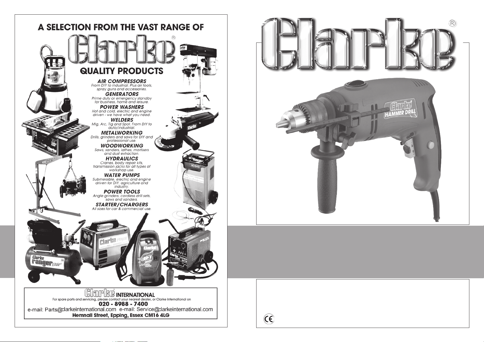
820 WATT HAMMER DRILL
820 WATT HAMMER DRILL
MODEL NO: CHD820
PART No: 6480115
OPERATION & MAINTENANCE
INSTRUCTIONS
0205
Page 2
HAND-ARM VIBRATION
Employers are advised to refer to the HSE publication “Guide for Employers”.
All hand held power tools vibrate to some extent, and this vibration is transmitted to the operator
via the handle, or hand used to steady the tool. Vibration from about 2 to 1500 herz is potentially
damaging and is most hazardous in the range from about 5 to 20 herz.
Operators who are regularly exposed to vibration may suffer from Hand Arm Vibration Syndrome
(HAVS), which includes ‘dead hand’, ‘dead finger’, and ‘white finger’. These are painful
conditions and are widespread in industries where vibrating tools are used.
The health risk depends upon the vibration level and the length of time of exposure to it……in
effect, a daily vibration dose.
Tools are tested using specialised equipment, to approximate the vibration level generated under
normal, acceptable operating conditions for the tool in question. For example, a grinder used at
45° on mild steel plate, or a sander on soft wood in a horizontal plane etc.
These tests produce a value ‘a’, expressed in metres per second per second, which represents the
average vibration level of all tests taken, in three axes where necessary, and a second figure ‘K’,
which represents the uncertainty factor, i.e. a value in excess of ‘a’, to which the tool could
vibrate under normal conditions. These values appear in the declaration on page 7.
You will note that a third value is given in the specification - the highest measured reading in a
single plane. This is the maximum level of vibration measured during testing in one of the axes,
and this should also be taken into account when making a risk assessment.
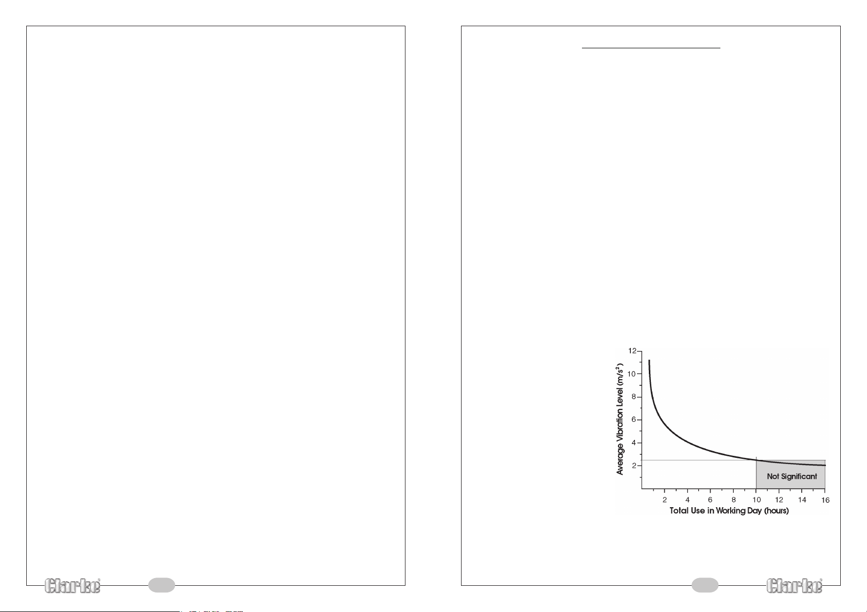
‘a’ values in excess of 2.5 m/s2 are considered hazardous when used for prolonged periods. A
tool with a vibration value of 2.8 m/s2 may be used for up to 8 hours (cumulative) per day,
whereas a tool with a value of 11.2 m/s2 may be used for ½ hour per day only.
The graph below shows the vibration value against the maximum time the respective tool may
be used, per day.
Please note that the details and specifications contained herein, are correct at the time of going to print. However,
CLARKE International reserve the right to change specifications at any time without prior notice.
1
The uncertainty factor should also be
taken into account when assessing a
risk. The two figures ‘a’ and ‘K’ may
be added together and the resultant
value used to assess the risk.
It should be noted that if a tool is used
under abnormal, or unusual
conditions, then the vibration level
could possibly increase significantly.
Users must always take this into
account and make their own risk
assessment, using the graph as a
reference.
Some tools with a high vibration value, such as impact wrenches, are generally used for a few
seconds at a time, therefore the cumulative time may only be in the order of a few minutes per
day. Nevertheless, the cumulative effect, particularly when added to that of other hand held
power tools that may be used, must always be taken into account when the total daily dose rate
is determined.
10
Page 3
Thank you for purchasing this CLARKE 13mm Hammer Drill, which is designed for DIY use
only
Before attempting to use the Drill, please read this manual thoroughly and follow the
instructions carefully. In doing so you will ensure the safety of yourself and that of others
around you, and you can look forward to the tool giving you long and satisfactory service.
HAND-ARM VIBRATION
Refer to notes on page 10
MODEL No: CHD820
DESCRIPTION: 13mm HAMMER DRILL
Declared vibration emission value in accordance
with EN12096
Measured vibration emission value -
Highest measured reading in a single plane 15.205 m/s
Values determined according to EN28622-1
a:
12.78 m/s
2
2
PARTS & SERVICE TEL: 020 8988 7400
CLARKE GUARANTEE
This CLARKE product is guaranteed against faulty manufacture for a period of 12
months from the date of purchase. Please keep your receipt as proof of purchase.
This guarantee is invalid if the product is found to have been abused or tampered
with in any way, or not used for the purpose for which it was intended.
Faulty goods should be returned to their place of purchase, no product can be
returned to us without prior permission.
This guarantee does not effect your statutory rights.
Specifications
Model No: ..................................................... CHD820
Part No: ......................................................... 6480115
Chuck Capacity: ......................................... 13mm
Drill Capacity:
In Wood:.............................. 35mm
In Steel: ................................ 13mm
In Concrete: ....................... 13mm
Voltage: ........................................................ 230vac @ 50Hz
Power: ........................................................... 820w
Noise Level: ................................................... 111.2dB(A)
Vibration Level: ............................................ see notes on page 9
No load Speed: ............................................ 0-2500 RPM
Full Load Blows: ............................................ 40,000 bpm
Net Weight: ................................................... 2.4Kg
or e-mail as follows:
PARTS: [email protected]
SERVICE: [email protected]
9 2
Check List
1 x Operating & Instruction Manual
1 x Impact Drill
1 x Auxiliary Handle Assembly
1 x Chuck Key
1 x Depth Gauge Rod
Page 4
Safety Precautions
WARNING:
As with all tools and machinery, there are certain hazards involved with their
operation and use. Exercising respect and caution will considerably lessen the
risk of personal injury. However, if normal safety precautions are overlooked or
ignored, personal injury to the operator or damage to property, may result.
1. ALWAY S Learn the tool/machines applications, limitations and the
specific potential hazards peculiar to it. Read and become familiar
with the entire operating manual.
2. ALWAY S use a face or dust mask if operation is particularly dusty.
3. ALWAY S check for damage. Before using the machine, any
damaged part, should be checked to ensure that it will operate
properly, and perform its intended function. Check for alignment
of moving parts, breakage of parts, mountings, and any other
condition that may affect the tool/machines operation. Any damage should be
properly repaired or the part replaced. If in doubt, DO NOT use the machine.
Consult your local dealer.
4. ALWAY S disconnect the tool/machine from the power supply before servicing and
when changing accessories.
5. ALWAY S wear safety goggles, manufactured to the latest European Safety Standards.
Everyday eyeglasses do not have impact resistant lenses, they are not safety glasses.
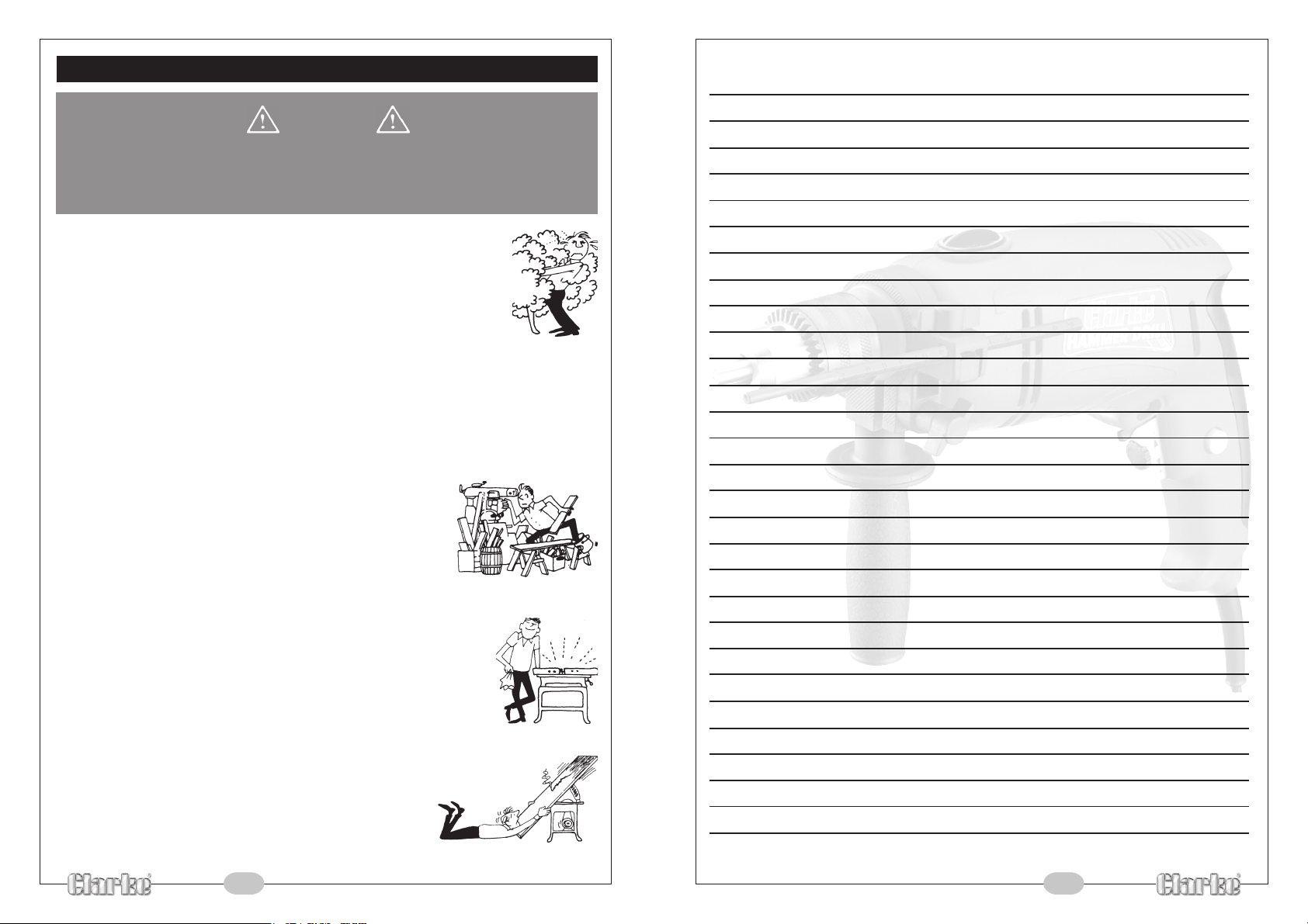
6. ALWAY S keep work area clean. Cluttered areas and
benches invite accidents.
7. ALWAY S ensure that adequate lighting is available. A
minimum intensity of 300 lux should be provided. Ensure
that lighting is placed so that you will not be working in
your own shadow.
8. ALWAY S use ear defenders when using this tool., particularly
when hammer drilling.
9. ALWAY S maintain machine in top condition. Keep tools/machines
clean for the best and safest performance. Follow maintenance
instructions.
10. ALWAY S handle with extreme care do not carry the tool/machine
by its’ electric cable, or yank the cable to disconnect it from the
power supply.
11. ALWAY S ensure the switch is off before plugging in to mains. Avoid
accidental starting.
12. ALWAY S concentrate on the job in hand, no matter
how trivial it may seem. Be aware that accidents are
caused by carelessness due to familiarity.
13. ALWAY S keep your proper footing and balance at all
times - don’t overreach. For best footing, wear rubber
soled footwear. Keep floor clear of oil, scrap wood, etc.
NOTES
3 8
Page 5
Maintenance
Electrical Connections
Before commencing any maintenance procedures, ALWAYS ensure the drill is isolated from
the main electrical supply by switching off and removing the plug from the socket.
• Always keep the drill gun clean and free from dirt, grease, oil and other contaminants.
• DO NOT use solvents to clean the drill, wipe with a clean soft cloth, lightly dampened
with water only.
• If sparking within the housing becomes excessive, this indicates worn or faulty motor
brushes, consult your Clarke dealer.
• Never allow the ventilation slots to become blocked.
• Inspect the mains cable regularly for damage and replace if necessary, DO NOT use
if the cable is damaged.
Chuck Replacement:
Open the chuck jaws fully.
Using a cross head screwdriver, loosen and remove the chuck securing screw located inside
the chuck, noting the screw has a left hand thread which requires turning in a clockwise
direction to unscrew it.
With the screw removed, proceed to
unscrew the chuck in an anticlockwise
direction and remove it from the drill.
If the chuck is difficult to unscrew, ( it may
maytighten with use), it is possible to hold
the drill shaft using a 13mm cycle type
spanner (not supplied) whilst unscrewing
the chuck.
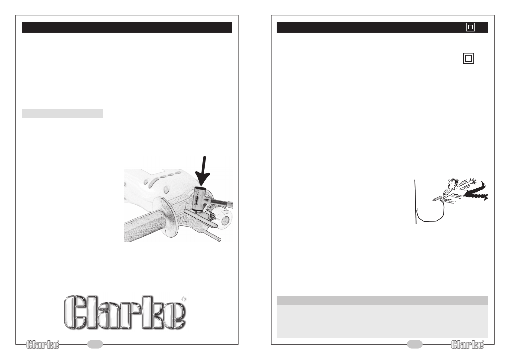
Alternatively, insert the chuck key into one
of the three holes in the chuck, apply a
swift blow with a hammer (preferably
plastic) to the key in the direction to
unscrew it (anticlockwise) - see illustration.
DO NOT repeatedly strike the chuck key
as this could lead to damaged bearings.
Fit replacement chuck in reverse order,
taking care not to cross thread the chuck or chuck securing screw.
DO NOT overtighten.
NOTE: If you have difficulty performing this operation, consult your nearest Clarke dealer.
Connect the mains lead to a standard 230V (50Hz) electrical supply through an approved
13 Amp BS1363 plug, or a suitably fused isolator switch.
WARNING: This appliance is DOUBLE INSULATED
IMPORTANT:
the following code:
As the colours of the flexible cord of this appliance may not correspond with the coloured
markings identifying terminals in your plug proceed as follows:
• Connect BROWN coloured cord to plug terminal marked with a letter L or coloured
RED
• Connect BLUE coloured cord to plug terminal marked with a letter N or coloured
BLACK
IMPORTANT:
the electric cable (i.e. non- re-wireable) please note:
1. The plug must be thrown away if it is cut from the
electric cable. There is a danger of electric shock if
it is subsequently inserted into a socket outlet.
2. Never use the plug without the fuse cover fitted.
3. Should you wish to replace a detachable fuse carrier,
ensure that the correct replacement is used (as
indicated by marking or colour code).
4. Replacement fuse covers can be obtained from
your local dealer or most electrical stockists.
5. The fuse in the plug must be replaced with one of the same rating (13 amps) and this
replacement must be approved to BS1362.
IMPORTANT: If in any doubt, do not attempt any electrical repair yourself.
Consult a qualified technician.
The wires in the mains lead are coloured in accordance with
Blue - Neutral
Brown - Live
If this appliance is fitted with a plug which is moulded on to
IMPORTANT:
If a cable extension is used, it is essential to comply with the following data.
Voltage Extension length Cable section
230v Up to 20m 2.5mm
230v From 20 to 50m 4mm
7 4
2
2
Page 6
Operation
Before plugging into the mains supply, ALWAYS fit the appropriate drill bit first, then pull the
trigger briefly and release, to ensure the drill is not locked in the ON position. When changing a drill bit, ALWAYS disconnect from the mains beforehand.
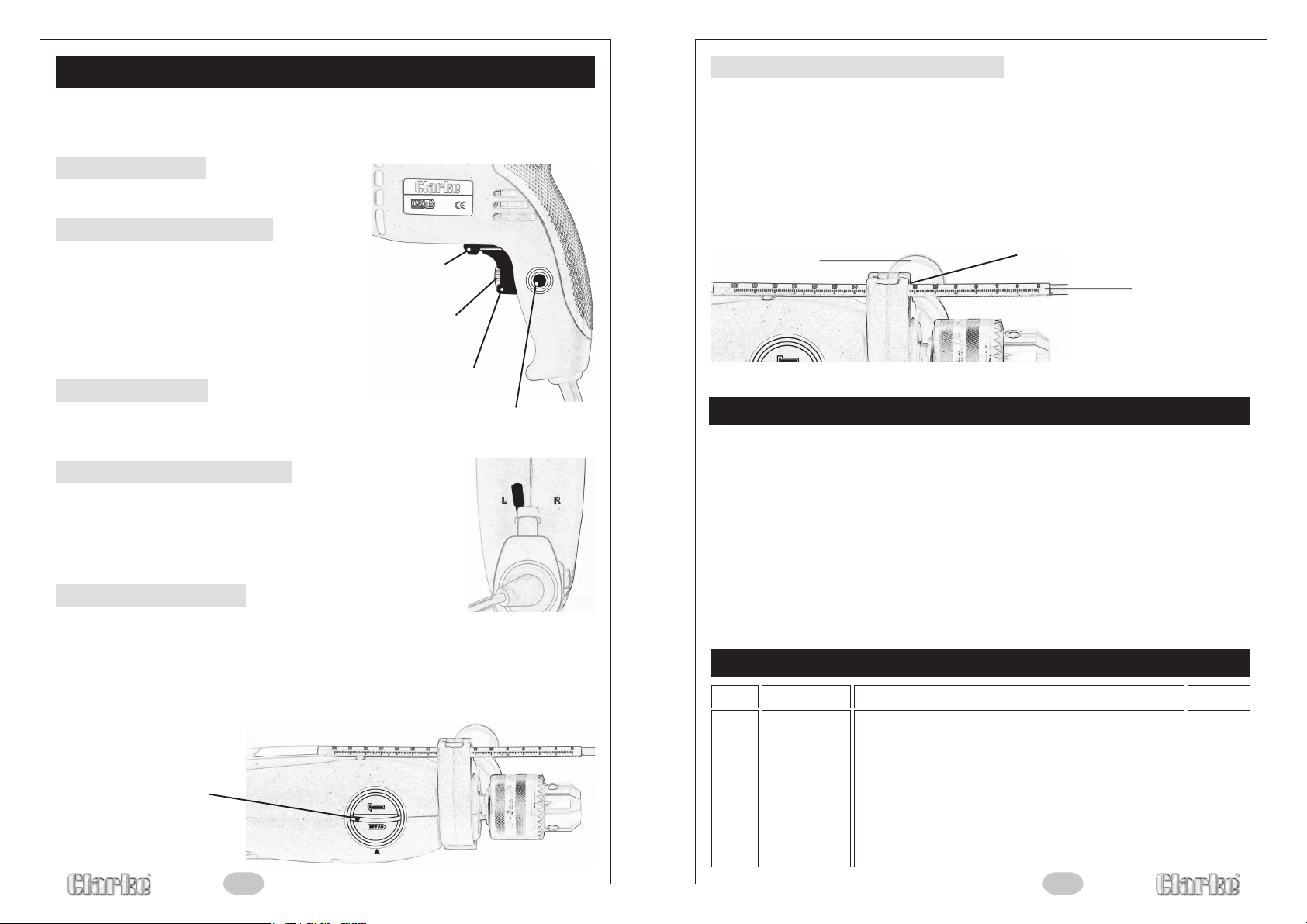
To Switch ON:
Plug into 13amp socket and squeeze the trigger.
Continuous Operation:
Squeeze the trigger and lock by pressing the
trigger lock button.
NOTE: The speed is varied by applying more
or less pressure on the trigger. The maximum
speed may be pre-selected by turning the
knurled variable speed control within the
trigger.
To switch OFF:
Operate the trigger briefly and then release, the switch will unlatch
and the motor will stop.
Forward/Reverse Selection:
Push the forward/reverse control lever towards ‘R’ normal rotation.
Push the forward/reverse control lever towards ‘L’ for reverse rotation.
DO NOT operate until the drill has come to a complete stop.
Hammer Selection:
Rotate the switch, on top of the drill, to the ‘Hammer’ position ~ denoted by a hammer
symbol.
For normal drilling the switch should be in the ‘Drill’ position, denoted by a drill bit symbol
(particularly when drilling tiles, ceramics etc.).
DO NOT operate until the drill has come to a complete stop.
MODE SWITCH
(currently set to drill only)
FORWARD/REVERSE
CONTROL LEVER
VARIABLE SPEED
CONTROL
TRIGGER
TRIGGER LOCK BUTTON
Auxiliary Handle And Depth Stop:
The depth stop is fitted with the auxiliary handle and can only be used if this handle is
installed, to install, simply locate the handle assembly over the chuck and onto the body of
the drill, insert the depth stop rod into the holder in the handle assy, rotate the handle to the
desired position and secure in position by turning the handle clockwise, DO NOT overtighten.
To set the depth stop, loosen the handle by turning anticlockwise sufficiently to be able to
slide the rod or and out to the required position, the scale markings on the rod are for
reference only.
HANDLE
HOLDER
DEPTH STOP ROD
General Drilling Advice
• After drilling material to the full depth, do not simply pull out the drill but maintain
chuck rotation to ease withdrawal.
• Keep drill bits sharpened for optimum performance.
• Always drill directly in line with the bit. Do not use sideways movement as this may
damage the drill or cause the bit to break.
• Always use a cutting lubricant when drilling all metals except brass and cast iron
which should be drilled dry.
•
If the drill is not cutting the metal then sharpen the drill, ensuring the various cutting angles
are correct. Consult a suitable book of reference or a qualified technician.
If in doubt, contact your nearest Clarke dealer.
Spare Parts
Item Part No Description Qty
01 TMC82001 Chuck 1
02 TMC82002 Chuck Securing Screw 1
03 TMC82003 Chuck Key 1
04 TMC82004 Auxiliary Handle Assembly 1
05 TMC82005 Depth Gauge Rod 1
06 TMC82006 Power Cable Incl. Plug 1
5 6
 Loading...