

Page 1

9” (230mm)
9” (230mm)
ANGLE GRINDER
ANGLE GRINDER
Model No. CAG232
OPERATING & MAINTENANCE
INSTRUCTIONS
0105
©
Page 2
SPECIFICATIONS
Motor ............................................................. 230V~ 50Hz 1ph
Power Rating ................................................. 2000Watts
Fuse Rating .................................................... 13Amps
No Load Speed ............................................. 6,000RPM
Wheel/Disc Dia. ............................................ 230mm (9”)
Wheel/Disc Bore ........................................... 22mm
Sound Power Level ....................................... 110 dBL
Vibration Level .............................................. <2.5m/s
Weight (Net) .................................................. 6kg
Part No. .......................................................... 6470097
Please note that the details and specifications contained herein, are correct at the time of going to
print. However, CLARKE International reserve the right to change specifications at any time without
prior notice. Always consult the machine’s data plate
WA
2
CONTENTS
Specifications ............................................................................... 2
Spare Parts and Service contacts ............................................. 2
Safety Precautions ....................................................................... 3
Additional Precautions for Angle Grinders ................................ 4
Electrical Connections ................................................................ 6
Features ........................................................................................ 7
Assembly ....................................................................................... 8
Operation ..................................................................................... 9
Maintenance ............................................................................. 10
Declaration of Conformity ........................................................ 10
Spare Parts Diagram ................................................................. 11
Disposal ....................................................................................... 11
© Copyright Clarke International. All rights reserved. July 98.
SPARE PARTS AND SERVICE CONTACTS
For Spare Parts and Service, please contact your nearest dealer,
or CLARKE International, on one of the following numbers.
PARTS & SERVICE TEL: 020 8988 7400
PARTS & SERVICE FAX: 020 8558 3622
or e-mail as follows:
PARTS: [email protected]
SERVICE: [email protected]
2
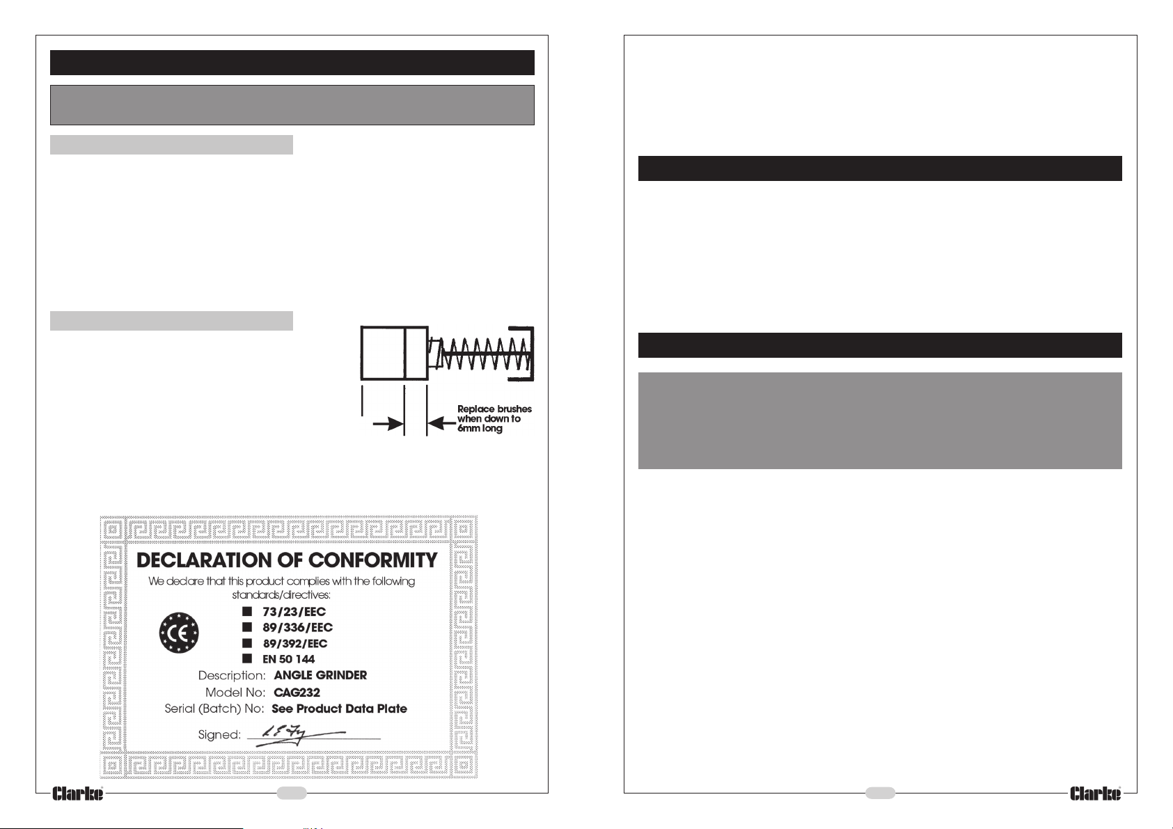
PARTS DIAGRAM
SPARE PARTS
1. Brush Set Part No. HTCAG23201
2. Hand Grip HTCAG23202
3. Guard HTCAG23203
4. Brush Cap HTCAG23204
5. Outer Flange HTCAG23205
6. Inner Flange HTCAG23206
7. Flange Tool HTCAG23207
8. Grinding Wheel/Cutting Disc (See below)
The following Grinding Wheels/ Cutting Discs are available from your Clarke dealer.
1. Metal Grinding (DPC) 230mm x 6mm thickness Part No. 6470720
2. Metal Cutting (Flat) 230mm x 3mm thickness 6470790
3. Masonry Cutting (Flat) 230mm x 3mm thickness 6470750
Diamond blades are also available, please see your Clarke dealer.
DISPOSAL
Waste electrical products should not be disposed of with household waste. Please
dispose of at your local recycling facility.
11
Page 3
MAINTENANCE
IMPORTANT: Before carrying out any maintenance tasks, ALWAYS disconnect
the tool from the mains electrical supply.
Before Each Use
Thank you for selecting this CLARKE 230mm (9”) Angle Grinder, designed for use
in a light industrial environment.
Before attempting to use the tool, please read this leaflet thoroughly and follow
the instructions carefully. In doing so you will ensure the safety of yourself and that
of others around you, and you can look forward to the Angle Grinder giving you
long and satisfactory service.
1. Always inspect the tool before use, and ensure it is in top condition.
2. Ensure air vents are clear, use compressed air at low pressure, to clean the tool
where possible. (Always wear protective goggles when using compressed air).
3. Check the power cable to ensure it is sound and free from cracks, bare wires etc.
4. Ensure the grinding wheel or cutting disc is perfectly sound, free from cracks
or damage in any way. Replace the disc when it is worn to 150mm diameter,
or if it is chipped or cracked. Never use the grinder with a damaged disc.
Only fit replacement discs with an outside diameter of 230mm (9”), and a
bore of 22mm. If in doubt, consult your dealer.
After every 50 hours of use.
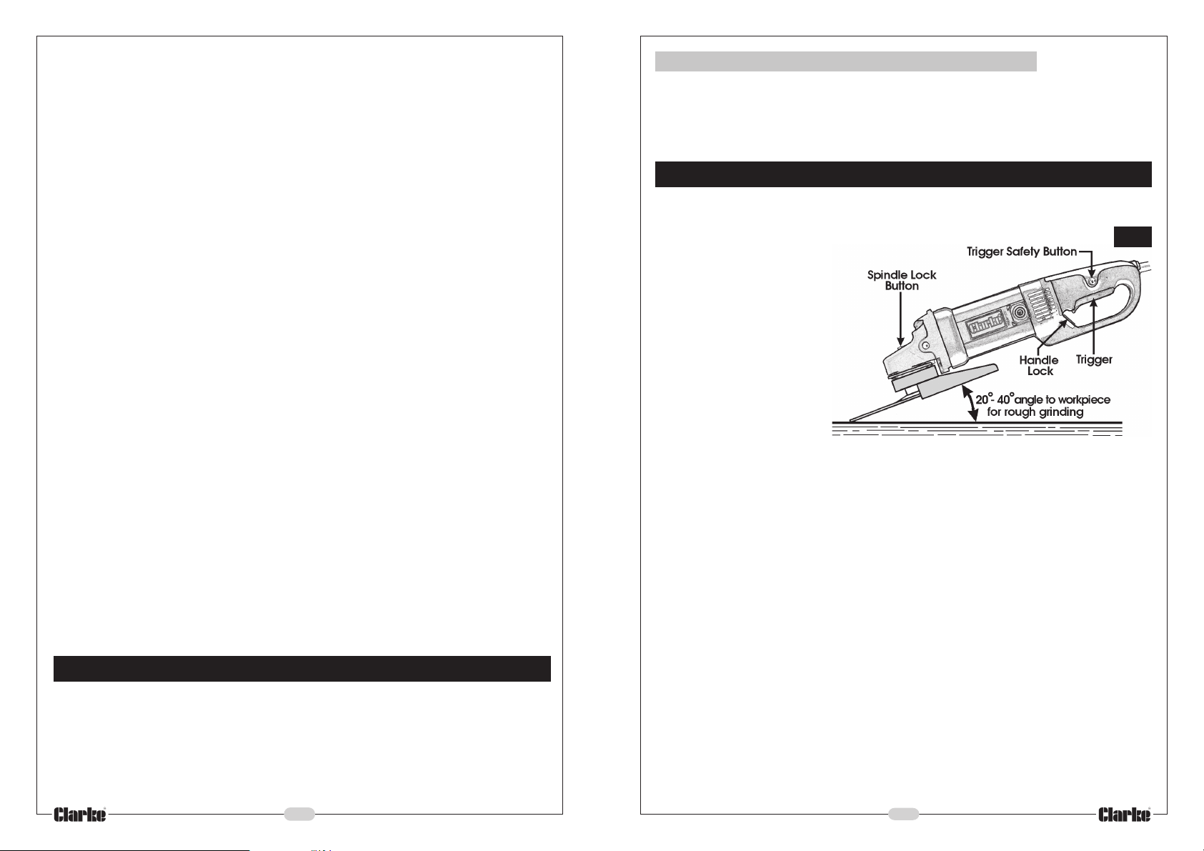
Unscrew Carbon Brush Caps, withdraw the Carbon
Brushes and check their condition. They must be
replaced when they have worn down to 6mm in
length. If they are found to be serviceable, blow the
brush holder clean with low pressure compressed air,
and replace. Take care to avoid damaging the spring
or wire when changing brushes.
The gearbox and motor are lubricated during manufacture, and further lubrication
is not normally needed.
GUARANTEE
This product is guaranteed against faulty manufacture for a period of 12 months
from the date of purchase. Please keep your receipt therefore, as proof of
purchase.
This guarantee is invalid if the product is found to have been abused or tampered
with in any way, or not used for the purpose for which it was intended.
Faulty goods should be returned to their place of purchase, no product can be
returned to us without prior permission. This guarantee does not effect your statutory
rights.
GENERAL SAFETY PRECAUTIONS
WARNING:
As with all machinery, there are certain hazards involved with their operation
and use. Exercising respect and caution will considerably lessen the risk of
personal injury. However, if normal safety precautions are overlooked or
ignored, personal injury to the operator or damage to property, may result.
1. READ and BECOME FAMILIAR with the entire operating manual. Learn the tools’
applications, limitations and the specific potential hazards peculiar to it.
2. ALWAYS ensure that ADEQUATE LIGHTING is available. A minimum intensity of
300 lux should be provided. Ensure that lighting is placed so that you will not
be working in your own shadow.
3. CHECK for DAMAGE. Before using the tool, any damaged part should be
checked to ensure that it will operate properly and perform its intended
function. Check for alignment of moving parts, breakage of parts, mountings
and any other condition that may affect the tools’ operation. Any damage
should be properly repaired or the part replaced. If in doubt, DO NOT USE the
tool. Consult your local dealer.
4. DISCONNECT the TOOL from the power supply before servicing and when
changing accessories.
5. ALWAYS WEAR SAFETY GOGGLES manufactured to the latest European Safety
Standards. Everyday eyeglasses do not have impact resistant lenses, they are
NOT safety glasses.
6. KEEP WORK AREA CLEAN. Cluttered areas and benches invite accidents.
10
3
Page 4
7. NEVER force the tool. It will do a better and safer job at the rate for which it
was designed.
8. ALWAYS USE A FACE OR DUST MASK if operation is particularly dusty.
9. DRUGS, ALCOHOL, MEDICATION. Do not operate tool while under the influence
of drugs, alcohol or any medication.
10. USE RECOMMENDED ACCESSORIES. The use of improper accessories could
be hazardous.
11. NEVER LEAVE THE TOOL RUNNING UNATTENDED. Turn power OFF. Do not leave
the tool until it comes to a complete stop.
12. AVOID DANGEROUS ENVIRONMENT. Don’t use power tools in damp or wet
locations or expose them to rain. Keep your work area well illuminated.
DO NOT USE in explosive atmosphere (around paint, flammable liquids etc.).
13. KEEP CHILDREN AWAY. All visitors should be kept a safe distance from the work
area, especially whilst operating the tool.
14. MAINTAIN TOOL IN TOP CONDITION. Keep tools clean for the best and safest
performance. Follow maintenance instructions.
15. DON’T OVERREACH. Keep your proper footing/balance at all times. For best
footing wear rubber soled footwear. Keep floor clear of oil, scrap wood, etc.
16. WEAR PROPER APPAREL. Loose clothing or jewellery may get caught in moving
parts. Wear protective hair covering to contain long hair.
17. HANDLE WITH EXTREME CARE Do Not carry the tool by its’ electric cable, or
yank the cable to disconnect it from the power supply .
18. AVOID ACCIDENTAL STARTING. Ensure the switch is OFF before plugging in to
mains.
19. BE AWARE that accidents are caused by carelessness due to familiarity.
ALWAYS concentrate on the job in hand, no matter how trivial it may seem.
20. ALWAYS store the tool in a clean dry environment when not in use, out of
reach of children
21. ALWAYS guard against electric shock, avoid contact with earthed surfaces -
pipes, radiators etc.
22. ALWAYS secure work - use a vise or clampswhenever possible.
ADDITIONAL PRECAUTIONS FOR ANGLE GRINDERS
1. It is strongly advised that you wear ear protectors/defenders as the noise
level during operation, depending upon the work being carried out, can
exceed safe working levels.
2. Always wear a good pair of industrial gloves to avoid potential injury from
sparks and debris.
3. Do not use the tool if the electric cable, plug or motor is in poor condition.
3.Hand Grip (3-position)
A threaded hole, on the top, left and right hand side of the gear housing, is provided
so that the hand grip may be screwed in, as required, to provide left or right hand
control of the tool.
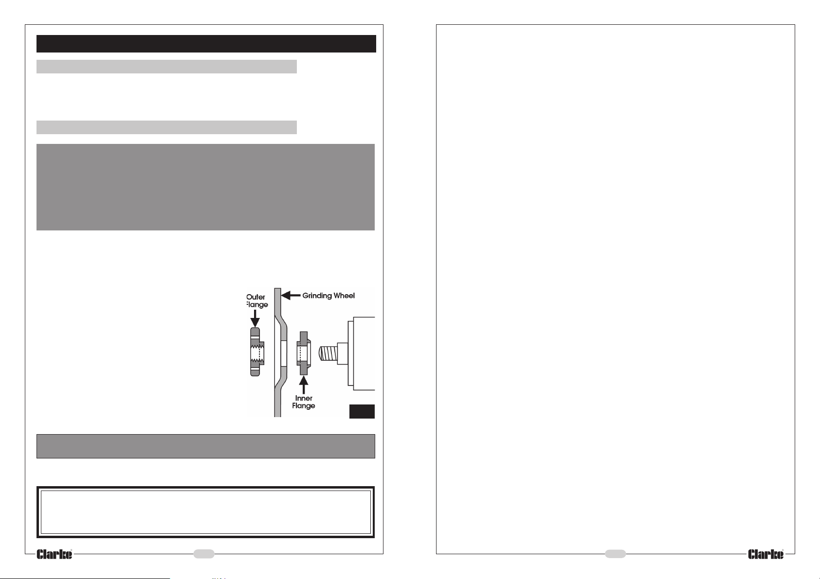
OPERATION Re: Fig.3
IMPORTANT! For safety, ensure the wheel is perfectly secure and the guard is set to
the desired position to give maximum protection, and is also secure.
Fig 3.
The hand holding the body
will control trigger switch,
whilst the other hand grasps
the hand grip and guides
the tool over the workpiece.
Holding the tool firmly but not
tightly, press the Trigger Safety
button and pull up the trigger.
The tool incorporates a ‘soft’
delayed start, therefore allow
a second or two for the tool
to reach full speed.
IMPORTANT! When renewing or replacing a disk/grinding wheel, ALWAYS allow
the tool to free run for at least one minute, to check the disk/wheel is mounted
correctly, any vibration should be investigated and rectified immediately. The
tool should not be used should vibrations exist.
Allow the tool to do the work...DO NOT force the disk on to the workpiece and
avoid putting any sideways pressure on cutting discs.
For rough grinding, hold the tool at an angle of 20-40 degrees to the work surface
as shown in Fig.2.
To stop the tool, simply release the trigger. There is NO trigger hold device as this is
undesirable for this type of tool. NEVER stop the grinder whilst it is in contact with
the work. ALWAYS wait until it has come to a compete stop before placing it down
carefully to avoid damaging the cutting/grinding disk.
If the machine is overloaded, or used for a long period, it will become hot. Running
the machine on no-load for a few minutes will allow the internal fan to cool the
motor to its normal temperature.
When using a cutting disk, avoid tilting the disk as it must present a clean cutting
edge to the work. NEVER use a cutting disk to cut asbestos, or for rough grinding,
or for side grinding.
4
9
Page 5
ASSEMBLY
1. Mounting the Blade Guard
Fit the blade guard to the shoulder of the grinder, ensuring it is fully located. Turn
the guard so that the open end is facing away, i.e. the opposite end to the handle,
then nip up the securing nut.
2. Mounting the Grinding Wheel/Cutting Disc.
WARNING!
ALWAYS check to ensure the machine is disconnected from the mains supply,
and that the grinding disk is suitable for the application in hand. The disk supplied
with this machine is suitable for grinding steel.
Consult your Clarke dealer if you need a disk for cutting or grinding other
materials...such as masonry etc.
Check also that the maximum RPM, marked on the disk exceeds 6000RPM.
2.1 Unscrew and remove the outer flange. If it is tight, lock the spindle by pressing
theSpindle Lock button (see Fig.3) and use thetool supplied to turn the flange to
break theseal. It may then be screwed off by hand.
2.2 The Grinding wheel supplied is a
‘Depressed Centre’ type, mount it as
shown in the Fig.1, i.e. with the depressed
centre towards the motor.
2. 3 Ensuring the wheel sits snugly over the raised
boss on the inner flange, screw on the outer
flange with the centre boss facing inwards.
Tighten the flange using the tool provided,
locking the spindle by pressing the Spindle
Lock button, and taking care to ensure
the wheel is still sitting snugly, centred over
the flange bosses. Care should be taken
also NOT to overtighten the outer flange.
WARNING! NEVER use reducing bushes or adapters to adapt large bore
abrasive wheels
2.4 Finally, rotate the disk by hand to ensure that does not foul the guard. If it
does, determine the cause and rectify before plugging in to a power supply.
Important:
Fig .2 shows the set up for a grinding wheel.
When attaching a cutting disk, YOU MUST REVERSE the Outer flange.
Fig 2.
4. Keep the mains cable well away from the tool and ensure an adequate
electrical supply is close at hand so that the operation is not restricted by the
length of the cable.
5. Switch the tool OFF immediately the task is completed and be aware that the
wheel/disc will continue to rotate for a period of time after switching off.
6. NEVER allow the ventilation slots in the tool to become blocked.
7. DO NOT attempt any electrical repair yourself. Consult a qualified electrician,
or our Service Dep’t on 020 8988 7400
8. DO NOT cut through walls or cavities before checking for hidden electrical
wires or water pipes etc.
9. Ensure the grinding wheel or cutting disc is fully tightened before use.
10. Do not use the tool in a confined space which may limit body movement.
11. Ensure the wheel/disc is not touching the work when switching ON.
12. Use only wheels/discs having a maximum operating speed of at least 6,000RPM.
13. Check the disk carefully for cracks or damage before operation. Replace
cracked or damaged wheels/discs immediately.
14. Take care not to damage the spindle or wheel flanges as damage to these
parts could result in wheel/disc breakage.
15. The angle grinder will ‘kick’ as it starts, so hold it firmly with both hands,
away from your body, when switching on.
16. Before using the tool on an actual workpiece, allow it to run briefly, checking for
vibration which could indicate poor balance or installation of the wheel/ disc.
17. Use only wheels/discs designed for their specific function. DO NOT use cutting
discs for grinding metal, or metal grinding wheels for cutting masonry.
18. Ensure tha wheel dimensions are compatible with the grinder.
19. ALWAYS follow the grinding wheel manufaturers recommendations for use and
store the wheels according to manufacturers instructions.
20. Beware of flying sparks. Keep clothing and other flammable materials well
away from flying sparks as fires could start after a short delay.
21. NEVER use excessive force. It should only be necessary to use a little more
than the weight of the tool. If the rotational speed drops abnormally, reduce
pressure immediately. Forcing the tool and excessive pressure can cause
dangerous disc breakage and/or damage to the tool.
22. NEVER use the tool with the guard removed. If the guard becomes damaged,
it should be replaced
Additionally, ALWAYS keep these instructions in a safe place for future reference.
8
5
Page 6
ELECTRICAL CONNECTIONS
FEATURES (ref. fig.2)
This model is provided with a 13 amp, 230 volt (50Hz), BS 1363 plug, for connection
to a standard, domestic electrical supply. Should the plug need changing at any
time, ensure that a plug of identical specification is used.
IMPORTANT:
This appliance is of Double Insulation construction
No earth conductor is provided. The two wires in the mains lead should be wired
up in accordance with the following colour code:
Blue — Neutral
Brown — Live
Connect the BROWN coloured cord to the plug terminal marked a letter “L”
Connect the BLUE coloured cord to the plug terminal marked a letter “N”
If this appliance is fitted with a plug which is moulded on to the electric cable (i.e.
non-rewireable) please note:
1. The plug must be thrown away if it is cut from the electric cable. There is a
danger of electric shock if it is subsequently inserted into a socket outlet.
2. Never use the plug without the fuse cover fitted.
3. Should you wish to replace a detachable fuse carrier, ensure that the correct
replacement is used (as indicated by marking or colour code).
4. Replacement fuse covers can be obtained from your local dealer or most
electrical stockists.
Fuse Rating
The fuse in the plug must be replaced with one of the same rating (13 amps) and
this replacement must be approved to BS1362.
If in doubt, consult a qualified electrician. Do not attempt any electrical repairs yourself.
Cable Extension
Do not use an extension longer than 10 metres and one where the conductors, are
less than 2.5mm2.
Ensure that the extension cable is designed for outdoor use.
1.Trigger Safety Button.
To operate the trigger it is first of all necessary to press the trigger safety button,
Press the button then pull the trigger to start, ensuring the machine is held firmly
and away from the body.
2.Spindle Lock Button.
When pressed, this button, located on top of the head, is used to lock the spindle
when attempting to unscrew and remove the outer flange (using the special tool
provided), in order to mount or change the grinding wheel or cutting disc.
WARNING:
NEVER press the spindle lock button when starting the tool, and
NEVER press the button when the tool is operating.
DO NOT press button until the wheel/disc has stopped completely
3. Quick Change Guard.
The guard is capable of rotating about its axis. Undo the clamp using an allen key and turn
to the desired position, then retighten the clamp before connecting the tool to the mains
supply and switching ON.
You should always turn the guard so as to provide the greatest amount of protection for
the hand gripping the hand grip, without impeding the work being carried out.
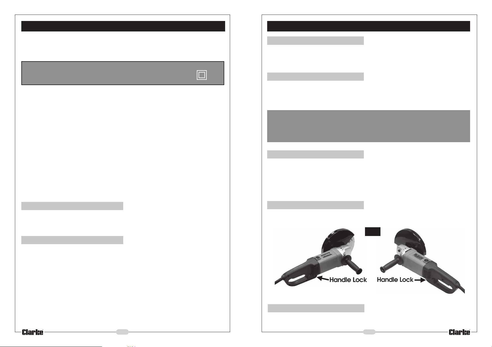
4. Rotating Handle
The handle is capable of rotating as shown in Fig.1. for left or right hand operation when
cutting. Simply pull back the Handle Lock (see Fig.3) and rotate the handle, left or right
until it clicks into place.
Fig 1.
Left Hand operation
Right Hand operation
5. Grinding Wheel
The grinding wheel supplied, must be used dry, and must not be used for cutting for
cutting
6
7
 Loading...