

Page 1

185MM CIRCULAR SAW
185MM CIRCULAR SAW
MODEL No. CCS2
Part No. 6462015
Part No. 6462040
OPERATING & MAINTENANCE
INSTRUCTIONS
©
0704
Page 2
Thank you for purchasing this CLARKE Circular Saw, designed for cutting wood ONLY.
Before attempting to use the machine, please read this manual thoroughly and follow the
instructions carefully. In doing so you will ensure the safety of yourself and that of others
around you, and you can look forward to the saw giving you long and satisfactory service.
Guarantee
This product is guaranteed against faulty manufacture for a period of 12 months from the
date of purchase. Please keep your receipt which will be required as proof of purchase.
This guarantee is invalid if the product is found to have been abused or tampered with in
any way, or not used for the purpose for which it was intended.
Faulty goods should be returned to their place of purchase, no product can be returned to
us without prior permission.
This guarantee does not effect your statutory rights.
Specifications
Mains Supply ..................................................................................... 230V 50Hz 1ph
Power Rating .................................................................................... 1300W
Fuse Rating ....................................................................................... 13amp
No Load Speed ................................................................................ 4,800 RPM
Guaranteed Sound Power Level (Under Load) .......................... 108.6dBL
Weight ............................................................................................... 6kg
Cutting Capacity @ 90º .................................................................. 60mm
Cutting Capacity @ 45º .................................................................. 45mm
Blade/Bore Diameter/Type ............................................................ 185/20mm/TCT
Dimensions ........................................................................................ 353x250x290mm
Part Number ..................................................................................... 6462040
Declared vibration emission value in accordance with
EN12096
Measured vibration emission value -
Uncertainty value -
K:
a:
<2.5m/s
0.99m/s
Highest measured reading in a single plane 4.56m/s
Values determined according to EN28622-1
This product Confirms to 98/37/EEC Regulations
Please note that the details and specifications contained herein, are correct at the time of going to print. However,
CLARKE International reserve the right to change specifications at any time without prior notice.
Copyright, Clarke International January,2004. All rights reserved.
2
WA
2
2
2
Parts List
No. Description Part No. No. Description Part No.
1 Screw TMCCCS201
2 Back Cover TMCCCS202
3 Screw TMCCCS203
4 Plate TMCCCS204
5 Brush Holder TMCCCS205
6 Carbon Brush TMCCCS206
7 Carbon Brush Cap TMCCCS207
8 Handle TMCCCS208
9 Housing TMCCCS209
10 Stator TMCCCS210
11 Screw TMCCCS211
12 End Plate TMCCCS212
13 Bearing Sleeve TMCCCS213
14 Bearing 609 TMCCCS214
15 Armature TMCCCS215
16 Bearing TMCCCS216
17 Case TMCCCS217
18 Spring TMCCCS218
19 Self-locking Bolt TMCCCS219
20 Button TMCCCS220
21 Upper Blade Guard TMCCCS221
22 Screw TMCCCS222
23 Bracket TMCCCS223
24 Brace TMCCCS224
25 Washer TMCCCS225
26 Nut TMCCCS226
27 Ring TMCCCS227
28 Bevel Locking Lever TMCCCS228
29 Washer TMCCCS229
30 Screw TMCCCS230
31 Long Rivet TMCCCS231
32 Spindle TMCCCS232
33 Screw TMCCCS233
34 Base TMCCCS234
35 Screw TMCCCS235
36 Depth Plate w/scale TMCCCS236
37 Rivet TMCCCS237
38 Handle TMCCCS238
PARTS & SERVICE TEL: 020 8988 7400
or e-mail as follows:
PARTS: [email protected]
SERVICE: [email protected]
39 Screw TMCCCS239
40 Cord Clamp TMCCCS240
41 Screw TMCCCS241
42 Rubber Handle TMCCCS242
43 Cable Gland/protector TMCCCS243
44 Capacitor TMCCCS244
45 Switch TMCCCS245
46 Handle Cover TMCCCS246
47 Screw TMCCCS247
48 Locking Lever TMCCCS248
49 Ring TMCCCS249
50 Depth Locking Lever TMCCCS250
51 Washer TMCCCS251
52 Screw TMCCCS252
53 Cable complete TMCCCS253
54 Needle Bearing TMCCCS254
55 Gear TMCCCS255
56 Woodruff Key TMCCCS256
57 Spindle TMCCCS257
58 Round Plate TMCCCS258
59 Bearing TMCCCS259
60 Front Cover TMCCCS260
61 Screw TMCCCS261
62 Riving Knife Bracket TMCCCS262
63 Nut TMCCCS263
64 Riving Knife TMCCCS264
65 Screw TMCCCS265
66 Rod TMCCCS266
67 Rivet TMCCCS267
68 Plastic Ring TMCCCS268
69 Lower Blade Guard TMCCCS269
70 Lever TMCCCS270
71 Screw TMCCCS271
72 Ring TMCCCS272
73 Inner Flange TMCCCS273
74 Blade See Dealer
75 Outer Flange TMCCCS275
76 Screw TMCCCS276
11
Page 3
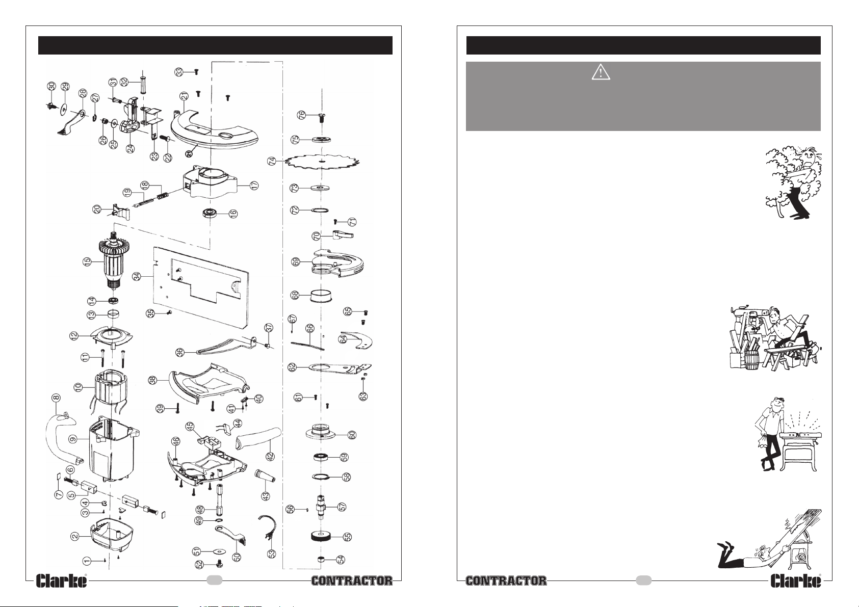
Parts Diagram
Safety Precautions
WARNING:
As with all machinery, there are certain hazards involved with their operation
and use. Exercising respect and caution will considerably lessen the risk of
personal injury. However, if normal safety precautions are overlooked or
ignored, personal injury to the operator or damage to property, may result.
1. ALWAY S learn the machines’ applications, limitations and the specific potential hazards
peculiar to it. Read and become familiar with the entire operating
manual.
2. ALWAY S use a face or dust mask if operation is particularly dusty.
3. ALWAYS check for damage. Before using the machine, any damaged
part, should be checked to ensure that it will operate properly, and
perform its intended function.
Check for alignment of moving parts, breakage of parts, mountings,
and any other condition that may affect the machines’ operation. Any damage
should be properly repaired or the part replaced. If in doubt, DO NOT use the machine.
Consult your local dealer.
4. ALWAYS disconnect the tool/machine from the power supply before servicing and when
changing accessories.
5. ALWAY S wear safety goggles, manufactured to the latest European Safety Standards.
Everyday eyeglasses do not have impact resistant lenses, they
are not safety glasses.
6. ALWAYS keep work area clean. Cluttered areas and benches
invite accidents.
7. A LWAYS ensure that adequate lighting is available. A minimum
intensity of 300 lux should be provided. Ensure that lighting is
placed so that you will not be working in your own shadow.
8. ALWAY S keep children away. All visitors should be kept a safe distance from the work
area, especially whilst operating the machine.
9. ALWAY S use CLARKE replacement blades. The use of improper
parts/accessories could be hazardous.
10. ALWAYS maintain machine in top condition. Keep tools/machines
clean for the best and safest performance. Follow maintenance
instructions.
11. ALWAYS handle with extreme care do not carry the tool/machine
by its’ electric cable, or yank the cable to disconnect it from the power supply .
12. ALWAYS ensure the switch is off before plugging in to mains. avoid accidental starting.
13. ALWAYS concentrate on the job in hand, no matter how
trivial it may seem. Be aware that accidents are caused
by carelessness due to familiarity.
14. ALWAYS keep your proper footing and balance at all times
don’t overreach. For best footing, wear rubber soled
footwear. Keep floor clear of oil, scrap wood, etc.
10
3
Page 4
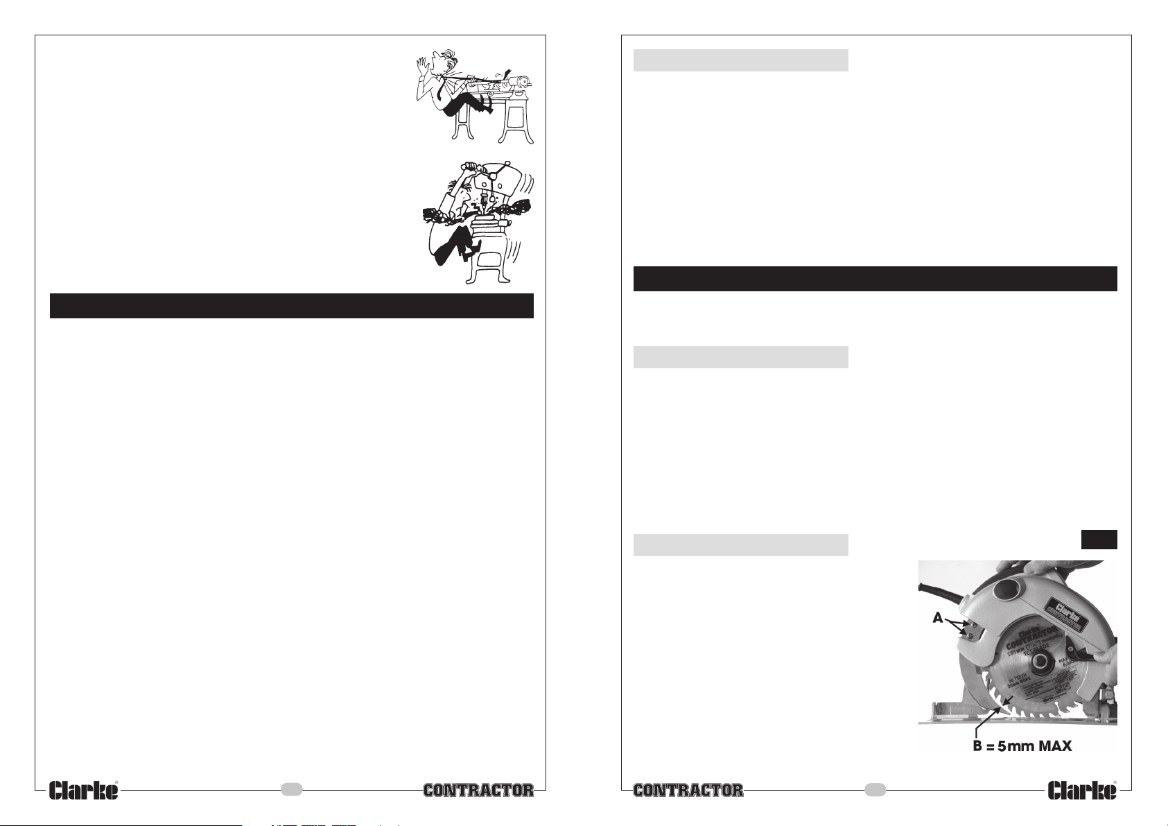
15. ALWAYS wear proper apparel. Loose clothing or jewellery may
get caught in moving parts. Wear protective hair covering to
contain long hair.
16. ALWAYS remove plug from electrical outlet when adjusting,
changing parts, or working on the machine.
17. NEVER operate machine while under the influence of drugs, alcohol
or any medication.
18. NEVER leave machine running unattended. Turn power off. Do not
leave the machine until it comes to a complete stop.
19. NEVER force the machine, it will do a better and safer job at
the rate for which it was designed.
20. NEVER use power tools in damp or wet locations or expose
them to rain. Keep your work area well illuminated. Do not use
in explosive atmosphere (around paint, flammable liquids etc.).
Avoid dangerous environment.
Additional Precautions For Circular Saws
1. ALWAYS wear ear protectors/defenders when using this machine.
2. ALWAYS use the appropriate saw blade for the material being cut.
3. ALWAYS keep the mains cable well away from the machine and ensure an adequate
electrical supply is close at hand so that the operation is not restricted by the length of
the cable.
4. ALWAYS ensure the Riving Knife is in place and directly in line with the blade.
5. ALWAYS allow sufficient clearance beneath the work to ensure the blade does not
come into contact with the work bench or any other object.
6. ALWAYS ensure the blade is fully tightened before use.
7. ALWAYS use a rip fence or guide when ripping.
8. ALWAYS check blade guard has returned FULLY before putting saw down.
9. ALWAYS ensure that nails have been removed from a workpiece beforehand. Nails will
damage the saw blade.
10. NEVER operate the saw when the blade guard is not working properly. The Guard
should be checked for correct operation before each use.
11. NEVER use abrasive disks with this machine, it is designed to cut wood ONLY
12. NEVER start the saw when the blade is in contact with the work.
13. NEVER allow the ventilation slots in the motor to become blocked.
14. NEVER use the machine if the electric cable, plug or motor is in poor condition.
15. NEVER reach beneath the workpiece whilst cutting
16. If the blade binds whilst cutting, or cutting is interrupted, hold the saw firmly, release
the trigger and allow the blade to stop completely. NEVER attempt to remove the saw
when the blade is in motion, otherwise kickback will occur.
17. NEVER use the saw with the blade guard jammed open.
Note : The guard is operating correctly when it moves freely and readily returns to closed position
Additionally, please keep these instructions in a safe place for future reference.
4
Kickback
Kickback is when the saw is driven back fiercely into the hands of the operator, and may
be caused by the following:
a. The blade becoming twisted or misaligned in the cut.
b. Dull Blades...ALWAYS use a sharp, perfectly serviceable blade.
d. Workpiece not properly secured, or held down adequately
e. Wet, warped, green or pressure treated timber.
f. Riving Knife misaligned.
g. Sawing into knots, nails etc.
h. Forcing the tool.
i. Using improper saw blades.
j. Depth setting too great....do not exceed 3-4mm.
Always hold the saw firmly so as not to loose control should kickback occur.
Maintenance
The Saw is generally maintenance free, except for occasionally changing the saw blade,
described below, and maintaining in a clean condition, ensuring the motor vents are clear
at all times. Do not use solvents to clean body parts
Changing the Saw blade
Ensure the saw is isolated from the mains supply, by removing the plug from the socket.
Press the Spindle Locking Knob (N, Fig. 1) in order to hold the blade securely, then, using the
special wrench, (supplied), unscrew (anticlockwise) and remove the Blade Centre Bolt and
washer, followed by the Outer Flange.
Retract the Lower Blade Guard all the way up into the Upper Guard, and slide the blade
off the spindle and down through the slot, taking great care not to damage hands on the
saw’s teeth.
Replace in reverse order, ensuring the blade is the correct way round...i.e. The teeth
should be pointing FORWARDS at the bottom. Ensure also, the blade sits snugly on its
registration on the spindle before replacing the outer flange, washer and centre bolt,
which should then be tightened but taking care not to overtighten.
Riving Knife Adjustment
It is vital that the Riving knife is perfectly in-line with
the blade at all times with a gap of no more than
5mm exsisting between the blade and knife.
Should it be necessary to adjust the Knife, ensure the
tool is disconnected from the mains, then lower the
Guide Plate so that the blade depth is zero using the
locking lever, O Fig. 1, to reveal the two Riving Knife
securing screws - A, Fig.4. Slacken the screws sufficient
for the knife to be adjusted, ensuring the gap
between blade and knife - B, is no more than 5mm,
and constant along the length of the knife.
Additionally, the blade should not extend more than
5mm below the end of the riving knife.
Ensure the securing screws are tight before use.
NOTE: It may be necessary to bend the knife slightly to ensure it is directly in-line with the blade.
9
Fig. 4
Page 5
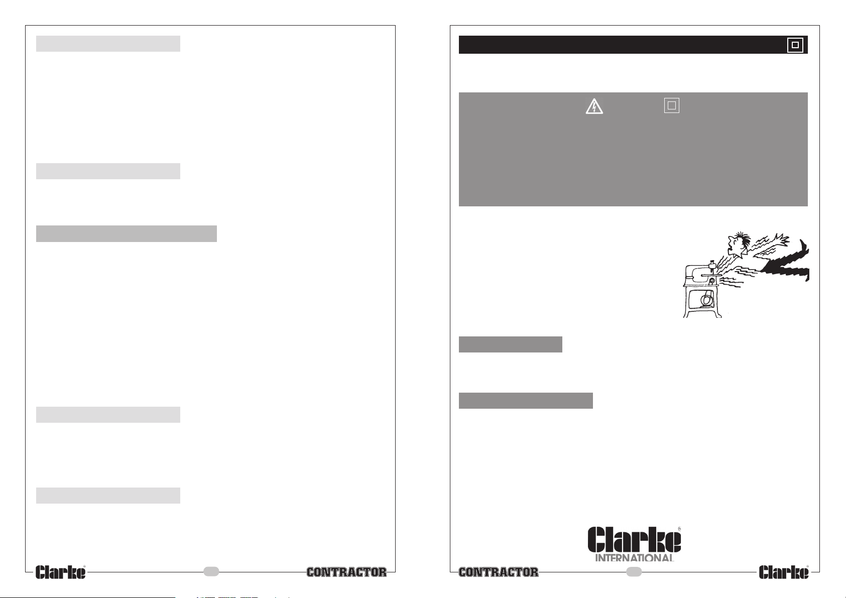
4. Starting
Place the leading edge of the Guide Plate on the top face of the workpiece,
ensuring the saw blade IS NOT making contact.
(See ‘General Notes’, which follow, for
more detailed information Re: marking the workpiece and accurate cutting etc.)
Hold the saw FIRMLY with both hands, then press the Interlock Button ‘M’ Fig. 1 and pull up
the ON/OFF switch.
The saw will start. Proceed to feed the saw into the work firmly and at a slow rate. Do not
force it.
Be aware that sawdust will be emitted from the dust extractor outlet. Suitable
precautions should be taken to protect property etc.
5. Stopping
Release the ON/OFF switch and allow the saw blade to stop completely before
withdrawing the saw from the cut. NEVER attempt to remove the saw with the
blade rotating and NEVER attempt to stop the blade by lateral pressure..
General Notes
1. Always support work as near as possible to the cut.
2. Support work so that the off-cut will be on your right hand side.
3. Clamp workpiece so that it will not move during the cut.
4. Side on which finished appearance is important should be face down.
5. Before beginning a cut, draw a guide line along the desired line of cut, then
place the front edge of the Guide Plate on that part of the work that is solidly
supported.....NEVER on the part of the work that will become the off-cut.
The notch on the front of the Guide Plate is marked 45
guideline with the 0O mark.
IMPORTANT! When marking your guideline, you must take into account the
thickness of the saw blade. This must be added to your desired width.
Since the blade thickness may vary, always test on a scrap piece first to determine
how much, if any, the guideline must be offset to produce your desired width.
Parallel Cut
Making a parallel cut using the Parallel Stop.
Position the face of the Stop firmly against the edge of the workpiece, this makes
a true cut without pinching the blade.
The guiding edge of the workpiece must be straight for your cut to be straight. Use
caution to prevent your blade from binding in the cut.
O
and 0O. Line up your
Electrical Connections
This product is provided with a standard 13 amp, 230 volt (50Hz), BS 1363 plug, for
connection to a standard, domestic electrical supply. Should the plug need changing at
any time, ensure that a plug of identical specification is used.
WARNING
This appliance is Double Insulated, and the two wires in the mains lead should
be wired up in accordance with the following colour code:
BLUE - NEUTRAL
BROWN - LIVE
•
Connect the BLUE coloured cord to the plug terminal marked a letter “N”
• Connect the BROWN coloured cord to the plug terminal marked a letter “L”
If this appliance is fitted with a plug which is moulded on to the electric cable (i.e. nonrewireable) please note:
1. The plug must be thrown away if it is cut from the
electric cable. There is a danger of electric shock if
it is subsequently inserted into a socket outlet.
2. Never use the plug without the fuse cover fitted.
3. Should you wish to replace a detachable fuse
carrier, ensure that the correct replacement is used
(as indicated by marking or colour code).
4. Replacement fuse covers can be obtained from
your local Clarke dealer or most electrical stockists.
FUSE RATING
The fuse in the plug must be replaced with one of the same rating (13 amps) and this
replacement must be ASTA approved to BS1362.
If in doubt, consult a qualified electrician. Do not attempt any electrical repairs yourself.
CABLE EXTENSION.
Always use an approved cable extension suitable for the power rating of this tool (see
specifications), the conductor size should also be at least the same size as that on the
machine, or larger. When using a cable reel, always unwind the cable completely.
Bevel Cut
The angle of cut of your saw can be adjusted from 0º and 45º, there is a cutting indication
notch in the sole plate to assist in lining up the line of cut.
Align your line of cut with the inner guide on the sole plate, (45º), when making full 45º
bevel cuts, make a test cut on a scrap piece first, again to determine how much offset,
if any, is needed in order to produce your desired width.
8
5
Page 6
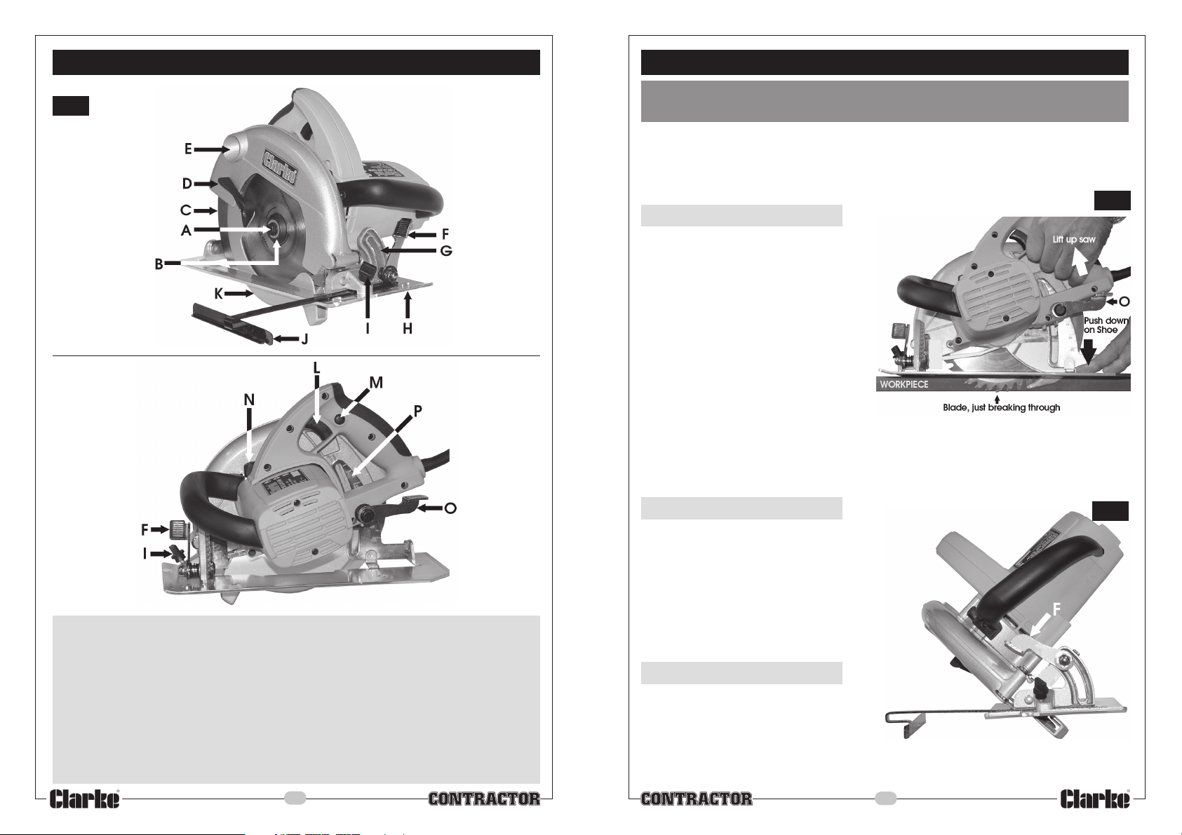
Features
Operation
Fig. 1
WARNING! This appliance should not be used by anyone not fully trained in
the use and operation of Power Tools
IMPORTANT!
Before use, ensure the workpiece is perfectly secure, and there is sufficient
clearance BENEATH the workpiece so that there is no possibility of the saw blade
coming into contact with any other object.
Fig. 2
1. Set the blade depth
.... so that the blade just breaks through the underside of
the workpiece. This is achieved as follows:
Raise the Lower Blade Guard using the
lever ’D’ Fig. 1, and lay the saw alongside
the workpiece so that the blade guard is
supported by the top surface of the
workpiece.
Unlock the Blade Depth Locking
Lever ‘O’ by pulling it upwards.
Hold down the Guide Plate whilst raising
the saw, and push downthe locking lever when
the blade is just of the workpiece, as illustrated.
The saw blade should never extend by more that 3- 4mm.
Failure to set the depth correctly will result in the Lower Blade Guard not operating
correctly and fouling the workpiece during the cutting process.
A - Saw Blade Centre Bolt
B - Saw Blade Outer Flange
C - Riving Knife
D - Lower Blade Guard Lever
E - Dust Extraction Outlet
F - Guide Plate (Bevel) Locking Lever
G - Blade Bevel Gauge
H - Guide Plate
I - Parallel Stop Locking screw
J - Parallel Stop
K - Lower Blade Guard
L - ON/OFF Switch
M - ON/OFF Switch Interlock Button
N - Spindle Lock
O - Blade Depth Locking Lever
P - Blade Depth Gauge
6
2. Set the blade angle
If Accuracy is required, use a protractor
against the saw blade and Guide Plate.
Unlock the Guide Plate using the locking lever ‘F’,
adjust accordingly then re-lock the Guide Plate.
For general use, a scale is provided, shown
at ‘G’ Fig. 1.
The illustration shows the blade set at 45
O
Fig. 3
3. Safety
Check that all parts are secure, including
the saw blade and Riving Knife, which
must be directly in line with the blade...if
it is not, it MUST be realigned before use.
Adjust the parallel stop if required. Ensure the mains cable is well away from the
saw blade and not looped under the workpiece, then plug into the mains supply.
7
 Loading...