

Page 1

VARIABLE SPEED
BISCUIT JOINTER
JIG SAW
BISCUIT JOINTER
MODEL No. CJS350
MODEL No. BJ600
OPERATING & MAINTENANCE
Part No. 6460200
Part No. 6462003
INSTRUCTIONS
0705
Page 2

This Page Intentionally Left Blank
This Page Intentionally Left Blank
-1-
-18-
Page 3
HAND-ARM VIBRATION
Employers are advised to refer to the HSE publication “Guide for Employers”.
This is an important document and should be retained
All hand held power tools vibrate to some extent, and this vibration is transmitted to the
operator via the handle, or hand used to steady the tool. Vibration from about 2 to 1500
hertz is potentially damaging and is most hazardous in the range from about 5 to 20 hertz.
Operators who are regularly exposed to vibration may suffer from Hand Arm Vibration
Syndrome (HAVS), which includes ‘dead hand’, ‘dead finger’, and ‘white finger’. These
are painful conditions and are widespread in industries where vibrating tools are used.
The health risk depends upon the vibration level and the length of time of exposure to
it……in effect, a daily vibration dose.
Tools are tested using specialised equipment, to approximate the vibration level generated
under normal, acceptable operating conditions for the tool in question. For example, a
grinder used at 45° on mild steel plate, or a sander on softwood in a horizontal plane etc.
These tests produce a value‘ a’, expressed in metres per second per second, which
represents the average vibration level of all tests taken, in three axes where necessary,
and a second figure ‘K’, which represents the uncertainty factor, i.e. a value in excess of
‘a’, to which the tool could vibrate under normal conditions. These values appear in the
declaration on page 7.
You will note that a third value is given in the specification - the highest measured reading
in a single plane. This is the maximum level of vibration measured during testing in one of
the axes, and this should also be taken into account when making a risk assessment.
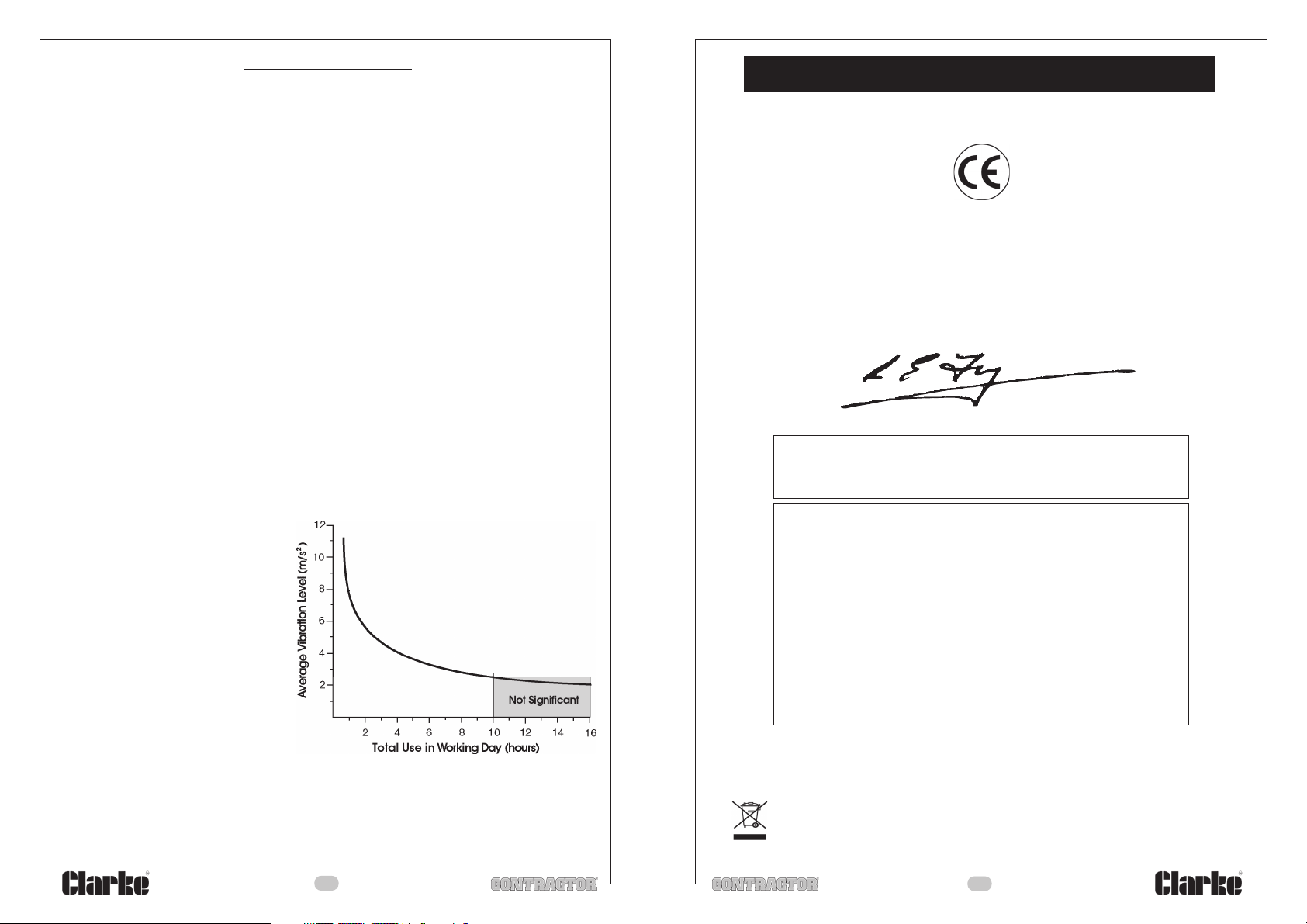
‘a’ values in excess of 2.5 m/s2 are considered hazardous when used for prolonged periods.
A tool with a vibration value of 2.8 m/s2 may be used for up to 8 hours (cumulative) per
day, whereas a tool with a value of 11.2 m/s2 may be used for ½ hour per day only.
The graph below shows the vibration value against the maximum time the respective tool
may be used, per day.
The uncertainty factor should also be
taken into account when assessing a
risk. The two figures ‘a’ and ‘
be added together and the resultant
value used to assess the risk.
It should be noted that if a tool is used
under abnormal, or unusual
conditions, then the vibration level
could possibly increase significantly.
Users must always take this into
account and make their own risk
assessment, using the graph as a
reference.
K’ may
DECLARATION OF CONFORMITY
We declare that this product complies with the following
standards/directives:
98/37EEC
89/336/EEC
72/23/EEC
MODEL No: BJ600
DESCRIPTION: BISCUIT JOINTER
Declared vibration emission value in accordance
with EN12096
Measured vibration emission value -
Uncertainty value -
K:
a:
2.28 m/s
5.57 m/s
Highest measured reading in a single plane 8.18 m/s
Values determined according to EN50144-1
2
2
2
Some tools with a high vibration value, such as impact wrenches, are generally used for a
few seconds at a time, therefore the cumulative time may only be in the order of a few
minutes per day. Nevertheless, the cumulative effect, particularly when added to that of
other hand held power tools that may be used, must always be taken into account when
the total daily dose rate is determined.
-17-
IMPORTANT!
When disposinjg of this product, ensure it is disposed of
according to all local ordinances
-2-
Page 4
Please read these instructions carefully before operating the tool
Thank you for purchasing this CLARKE biscuit jointer.
Before using the device, please read this manual thoroughly and carefully follow all
instructions given. This is for your own safety and that of others around you, and is also to
help you achieve a long and trouble free service from your new tool.
CLARKE GUARANTEE
This CLARKE product is guaranteed against faulty manufacture for a period
of 12 months from the date of purchase. Please keep your receipt as proof
of purchase.
This guarantee is invalid if the product is found to have been abused or
tampered with in any way, or not used for the purpose for which it was
intended.
Faulty goods should be returned to their place of purchase, no product
can be returned to us without prior permission.
This guarantee does not affect your statutory rights.
PARTS & SERVICE TEL: 020 8988 7400
or e-mail as follows:
PARTS: [email protected]
SERVICE: [email protected]
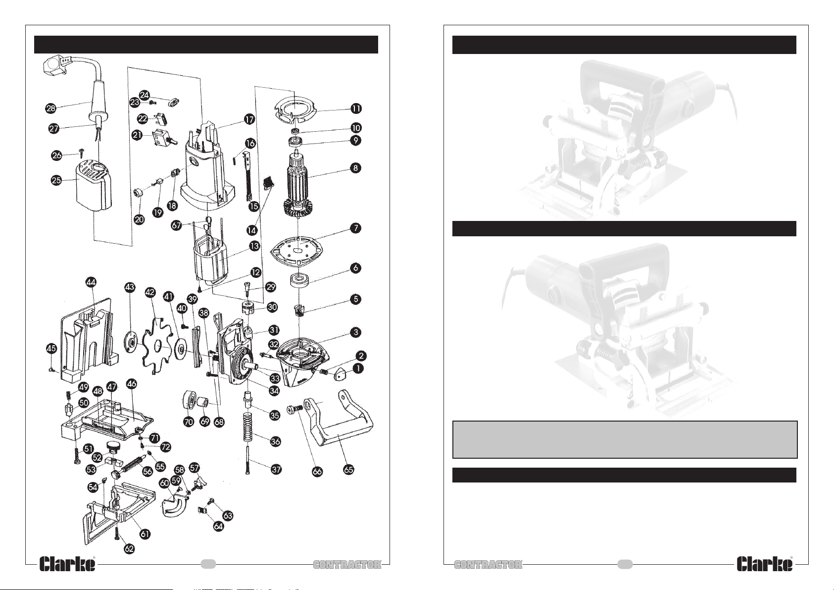
PARTS LIST
Item Part No Description Qty Item Part No Description Qty
1 HT60001 Pin Cap 1 38 HT60038 Screw M4x14 2
2 HT60002 Pin Spring 1 39 HT60039 Gib 2
3 HT60003 Gear Case 1 40 HT60040 Screw M4x12 4
5 HT60005 Pinion 1 41 HT60041 Inner Flange 1
6 HT60006 Ball Bearing 6000 1 42 HT60042 Cutter 1
7 HT60007 Bearing Retainer 1 43 HT60043 Outer Flange 1
8 HT60008 Armature 1 44 HT60044 Base Assembly 1
9 HT60009 Dust Guard 1 45 HT60045 C/Sunk Screw M5x10 2
10 HT60010 Ball bearing 606 1 46 HT60046 Carrier Support 1
11 HT60011 Fan Baffle 1 47 HT60047 Screw M4 x 4 1
12 HT60012 Screw ST3x10 1 48 HT60048 Scale 1
13 HT60013 Stator 1 49 HT60049 Compression Spring 2
14 HT60014 Switch Pusher 1 50 HT60050 Gripper 2
15 HT60015 Rod 1 51 HT60051 Screw M5x25 2
16 HT60016 Spring 1 52 HT60052 Knob 1
17 HT60017 Stator Case 1 53 HT60053 Clamp 1
18 HT60018 Brush holder 2 54 HT60054 Indicator 1
19 HT60019 Brush 2 55 HT60055 ‘O’ Ring 1
20 HT60020 Brush Cover 2 56 HT60056 Pinion & Rod 1
21 HT60021 Switch 1 57 HT60057 Knob 1
22 HT60022 Joint 1 58 HT60058 Washer 1
23 HT60023 Screw ST4x14 2 59 HT60059 Screw M4x8 1
24 HT60024 Cord Clamp 1 60 HT60060 Fence Angle Scale 1
25 HT60025 Rear Cover 1 61 HT60061 Fence 1
26 HT60026 Screw ST4x16 2 62 HT60062 Screw M5x22 2
27 HT60027 Cord & Plug 1 63 HT60063 Screw M4x8 1
28 HT60028 Cord Protector 1 64 HT60064 Pointer 1
29 HT60029 Shoulder Screw 1 65 HT60065 Handle 1
30 HT60030 Stop 1 66 HT60066 Screw M8x16 1
31 HT60031 Gear Case Cover 1 67 HT60067 Spring Link 1
32 HT60032 Lock Pin 1 68 HT60068 Screw M4x12 2
33 HT60033 Output Shaft 1 69 HT60069 Gear Washer 1
34 HT60034 Gear 1 70 HT60070 Ball Bearing 6201 1
35 HT60035 Guide 1 71 HT60071 Spring Washer 1
36 HT60036 Compression Spring 1 72 HT60072 Screw M5x6 1
37 HT60037 Shaft Screw 1
PARTS & SERVICE TEL: 020 8988 7400
or e-mail as follows:
PARTS: [email protected]
SERVICE: [email protected]
-3-
-16-
Page 5
PARTS DIAGRAM
CONTENTS
Guarantee : ..................................................................................... 3
Electrical Connections : ................................................................. 5
Safety Precautions : .............................................................. 6, 7 & 8
Adjustments : ....................................................................... 8, 9 & 10
Operating Instructions : ................................................. 10, 11 & 12
Blade Replacement : ................................................................... 12
Dust Extraction : ............................................................................ 13
Maintenance : .............................................................................. 13
Trouble Shooting : ......................................................................... 14
Parts List & Diagram : ........................................................... 15 & 16
Vibration Emissions : ............................ Refer To Notes On Page 17
SPECIFICATIONS
Model : ..................................................................................... BJ600
Part No : ............................................................................... 6462003
Voltage : .................................................................... 230vac - 50Hz
Power Rating : .......................................................... 600watt Motor
Fuse Rating : .......................................................................... 13amp
No Load Speed : ............................................................ 10,000 rpm
Saw Blade : ............................................................. Carbide Tipped
Blade Diameter : ........................................................... 100mm (4”)
Number of Teeth : ........................................................................... 6
Arbor : ......................................................................................22mm
Sound Power level : ....................................................... 97.5 dBLwa
Vibration : ..................................................................
See Page 2 & 17
-15-
Please note that the details and specifications contained herein are correct at the time of going to
print. However CLARKE International reserve the right to change specifications at any time without
prior notice. Always consult the machines data plate
ACCESSORIES
The biscuit jointer is supplied with the following accessories as standard:
1. Carbide-Tipped Blade.
2. Pin Wrench.
3. Dust Bag & Dust Extractor Adapter.
4. Operating and Maintenance Instructions.
-4-
Page 6

ELECTRICAL CONNECTIONS
This product is provided with a standard 13 amp, 230 volt (50Hz), BS 1363 plug, for connection
to a standard, domestic electrical supply. Should the plug need changing at any time,
ensure that a plug of identical specification is used.
WARNING
This appliance is Doubly Insulated, and the two wires in the mains lead should
be wired up in accordance with the following colour code:
BLUE - NEUTRAL
BROWN - LIVE
•
Connect the BLUE coloured cord to the plug terminal marked a letter “N”
• Connect the BROWN coloured cord to the plug terminal marked a letter “L”
If this appliance is fitted with a plug which is moulded on to the electric cable (i.e. nonrewireable) please note:
1. The plug must be thrown away if it is cut from the electric cable. There is a danger
of electric shock if it is subsequently inserted into a socket outlet.
2. Never use the plug without the fuse cover fitted.
3. Should you wish to replace a detachable fuse carrier, ensure that the correct
replacement is used (as indicated by marking or colour code).
4. Replacement fuse covers can be obtained from your local dealer or most electrical
stockists.
TROUBLE SHOOTING
Biscuit Jointer is overheating
This indicates the machine is dirty. Clean the ventilation holes, and blow out with compressed
air or clean with a dry cloth.
Overloading the machine will also cause overheating. Do not use for heavy duty work, and
do not apply excessive pressure.
Excessive sparking occurs
This indicates worn brushes. This problem is quickly remedied but you should consult your
CLARKE dealer for parts and advice.
Biscuit Jointer does not operate when switched ON
Check to ensure the fuse is sound and replace if necessary. If the fuse or blows repeatedly,
consult your CLARKE dealer.
Fuse Rating
The fuse in the plug must be replaced with one of the same rating (13 amps) and this
replacement must be ASTA approved to BS1362.
If in doubt, consult a qualified electrician. Do not attempt any electrical repairs yourself.
Cable Extension
Always use an approved cable extension suitable for the power rating of this tool (see
specifications), the conductor size should also be at least the same size as that on the
machine, or larger. When using a cable reel, always unwind the cable completely.
-5-
-14-
Page 7

DUST EXTRACTION
The jointer is provided with a dust extraction facility, where a vacuum extractor or dust
bag may be connected to the outlet at the rear of the machine. An adapter is provided
for this purpose. Please note however, that this does not preclude the user from wearing
a face mask to prevent the inhalation of dust particles.
Fitting The Dust Extractor
1. Lay the base of the biscuit jointer down on a flat surface.
2. Insert adapter into the dust exhaust port, attach the dust bag ensuring the zip is facing
downwards. Alternatively, fit the right angled adapter and attach a dust extractor
hose (Vacuum cleaner or similar).
Removing The Adaptor
1. Remove the dust bag, if fitted and empty contents into waste bin/bag. If using a
vacuum cleaner, remove hose.
2. Turn the jointer over and loosen the four base plate screws.
3. Pull the adapter free from the exhaust port, (it may be necessary to remove the screws
completely in order to remove the adapter ).
4. Re-tighten the four base plate screws.
It is an EEC requirement that a dust extraction facility be provided on power tools, however,
due to the nature of the tool, some of the dust produced will be forced into the surrounding
atmosphere, and will not be collected.
MAINTENANCE
Always inspect the tool before use, and ensure it is in top condition.
Ensure all air vents are clear, (use compressed air to clean the machine where possible).
Check the power cable to ensure it is sound and free from cracks, bare wires etc. avoid
using solvents when cleaning plastic parts, most plastics are susceptible to damage from
the various types of commercial solvents.
Lubricate all moving parts at regular intervals.
SAFETY PRECAUTIONS
WARNING:
As with all machinery, there are certain hazards involved with their operation
and use. Exercising respect and caution will considerably lessen the risk of
personal injury. However, if normal safety precautions are overlooked or
ignored, personal injury to the operator or damage to property, may result.
1. ALWAYS Learn the machines’ applications, limitations and the specific potential
hazards peculiar to it. Read and become familiar with the entire
operating manual.
2. ALWAYS use a face or dust mask.
3. ALWAYS check for damage. Before using the machine, any
damaged part, should be checked to ensure that it will operate
properly, and perform its intended function.
Check for alignment of moving parts, breakage of parts, mountings,
and any other condition that may affect the machines’ operation. Any damage
should be properly repaired or the part replaced. If in doubt, DO NOT use the machine.
Consult your local dealer.
4. ALWAYS disconnect the tool/machine from the power supply before servicing and
when changing accessories.
5. ALWAYS wear safety goggles, manufactured to the latest European Safety Standards.
Everyday eyeglasses do not have impact resistant lenses, they are not safety glasses.
6. ALWAYS keep work area clean. Cluttered areas and
benches invite accidents.
7. ALWAYS ensure that adequate lighting is available. A
minimum intensity of 300 lux should be provided. Ensure
that lighting is placed so that you will not be working in your
own shadow.
8. ALWAYS keep children away. All visitors should be kept a safe distance from the work
area, especially whilst operating the machine.
9. ALWAYS maintain machine in top condition. Keep tools/machines
clean for the best and safest performance. Follow maintenance
instructions.
10. ALWAYS handle with extreme care do not carry the tool/machine
by its’ electric c cable, or yank the cable to disconnect it from
the power supply .
11. ALWAYS ensure the switch is off before plugging in to mains. Avoid accidental starting.
12. ALWAYS concentrate on the job in hand, no matter how
trivial it may seem. Be aware that accidents are caused
by carelessness due to familiarity.
13. ALWAYS keep your proper footing and balance at all
times don’t overreach. For best footing, wear rubber
soled footwear. keep floor clear of oil, scrap wood, etc.
-13-
-6-
Page 8
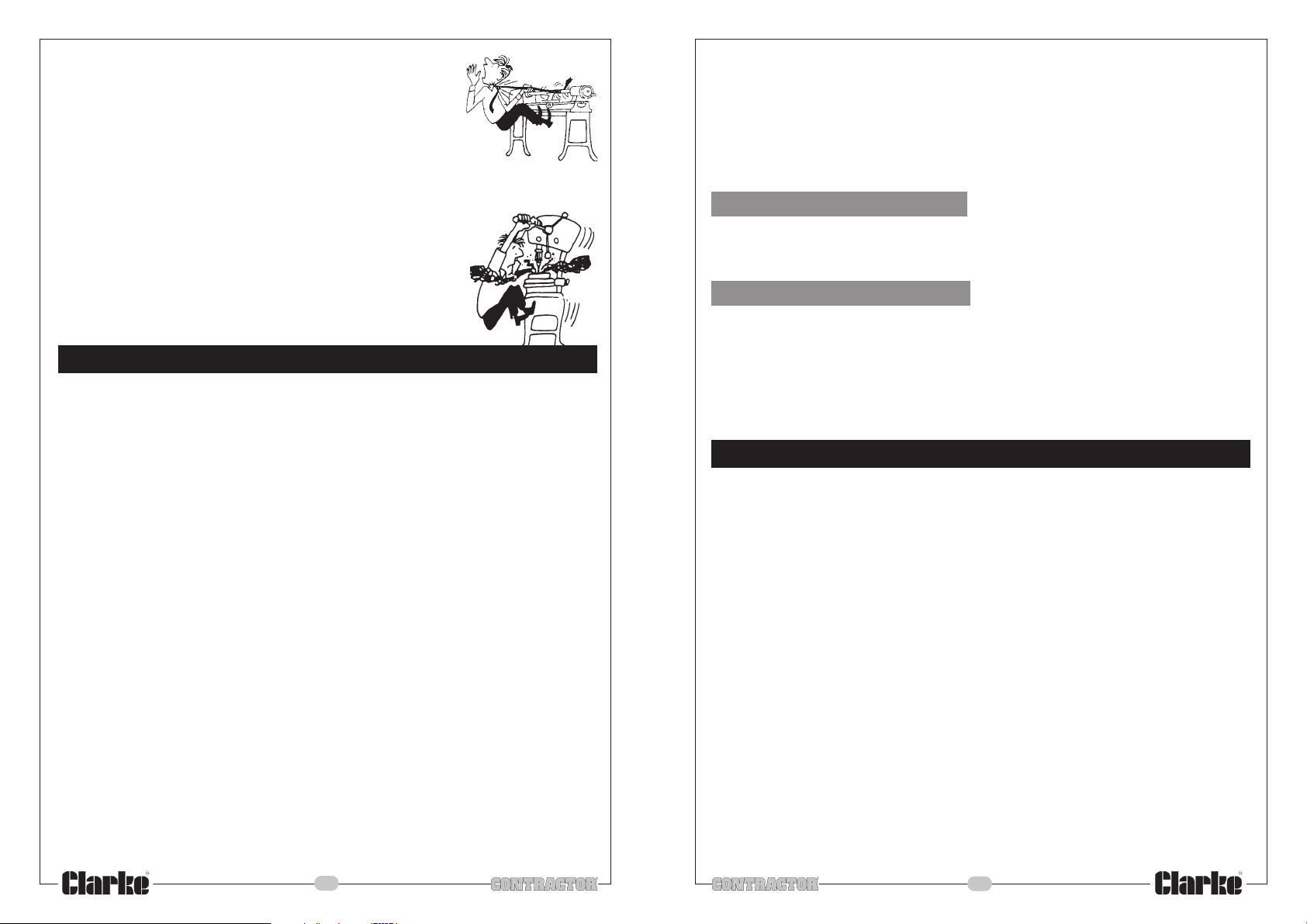
14. ALWAYS wear proper apparel. loose clothing or jewellery may
get caught in moving parts. wear protective hair covering to
contain long hair.
15. A LWAY S use recommended accessories. the use of improper
accessories could be hazardous.
16. A LWAY S remove plug from electrical outlet when adjusting,
changing parts, or working on the machine.
17. NEVER operate machine while under the influence of drugs, alcohol or any medication.
18. NEVER leave machine running unattended. turn power off.
Do not leave the machine until it comes to a complete stop.
19. NEVER force the machine. it will do a better and safer job at
the rate for which it was designed.
20. NEVER use power tools in damp or wet locations or expose
them to rain. Keep your work area well illuminated. do not
use in explosive atmosphere (around paint, flammable liquids
etc.). Avoid dangerous environment.D
ADDITIONAL PRECAUTIONS FOR POWER TOOLS
1. A LWAY S wear ear protectors/defenders as the noise level of this machine can exceed
85dB (A).
2. A LWAY S use the appropriate saw blade for the material being cut.
3. A LWAY S remove adjusting keys and wrenches etc before switching the tool on.
4. A LWAY S use clamps or a vice etc to hold the workpiece. It is safer and frees up both
hands to operate the tool.
5. DO NOT use the machine if the electric cable, plug or motor is in poor condition.
6. DO NOT Force the tool. The tool will do the job better and safer working at the rate it
was designed for.
7. DO NOT remove tool from work until the blade has completely stopped and power
removed.
8. DO NOT allow the ventilation slots in the machine to become blocked.
9. DO NOT touch the blade immediately after use, allow time for it to cool.
10. Replacement blades are available from your CLARKE dealer.
11. When cutting wood, ensure all nails have been removed beforehand. Nails will
damage the saw blade.
12. Ensure the blade is fully tightened before use.
13. Keep the mains cable well away from the blade and ensure an adequate electrical
supply is close at hand so that the operation is not restricted by the length of the
cable.
14. Avoid unintentional starting. Always check that the switch is in the OFF position before
plugging the tool into the power supply. Do not carry power tools with your finger on
the ON/OFF switch.
15. Switch the machine OFF immediately the task is completed.
Additionally, please keep these instructions in a safe place for future reference.
10. Repeat steps 5 - 10 until all slots are cut.
11 Apply glue to all slots using a nozzle applicator, ensuring glue gets right into slots.
12. Place biscuits in all slots on one piece to be joined, bring both pieces together
and clamp the joint until the biscuits swell and the glue sets.
NOTE:
On thick pieces of timber etc, it is possible to use two biscuits at each location, one at
1/3rd of the thickness and the other at 2/3rds.
Cutting A Mitre Joint
1. Slots can be cut in mitre joints with the workpiece secured flat on the bench and the
fence adjusted to the mitre angle.
2. A bevelled mitre joint has a biscuit slot cut at a 90º angle to the mitre cut.
Cutting Corner Joints
1. Set the pieces together and draw the joint centres on the outside face and end.
2. Cut the slots into the end piece.
3. Clamp the matching face piece so that it protrudes above your workbench with a
backing board supporting it from behind.
4. Cut the slots in the face piece
BLADE REPLACEMENT
1. Switch off and isolate from the main power supply by removing the plug from the
socket.
2. Turn the jointer over and unscrew and remove the four screws in the base plate
(Fig.4 page 11). Pivot the base plate off the two location roll pins.
3. Now with the blade exposed, depress the blade lock (Fig.3 page 11), rotate the
blade by hand until the blade locks.
4. Using the pin wrench supplied, loosen the blade flange by turning it anticlockwise.
5. Remove the outer blade flange.
6. Remove the blade from the inner flange.
7. Clean inner and outer blade flanges thoroughly before fitting new blade.
8. Fit the new blade in reverse order, ensure the direction of rotation of the saw blade
conforms to the direction of the arrow marked on the gear case.
9. Refit the outer flange and tighten using the pin wrench.
10. Turn the blade by hand to ensure the blade lock is released, also check the blade
runs freely.
11. Refit the base plate onto the two location pins and secure with the four screws
removed earlier.
12. Plug in and switch the jointer on with no load, check the motor and blade run freely
before attempting to use the tool again.
-7-
-12-
Page 9
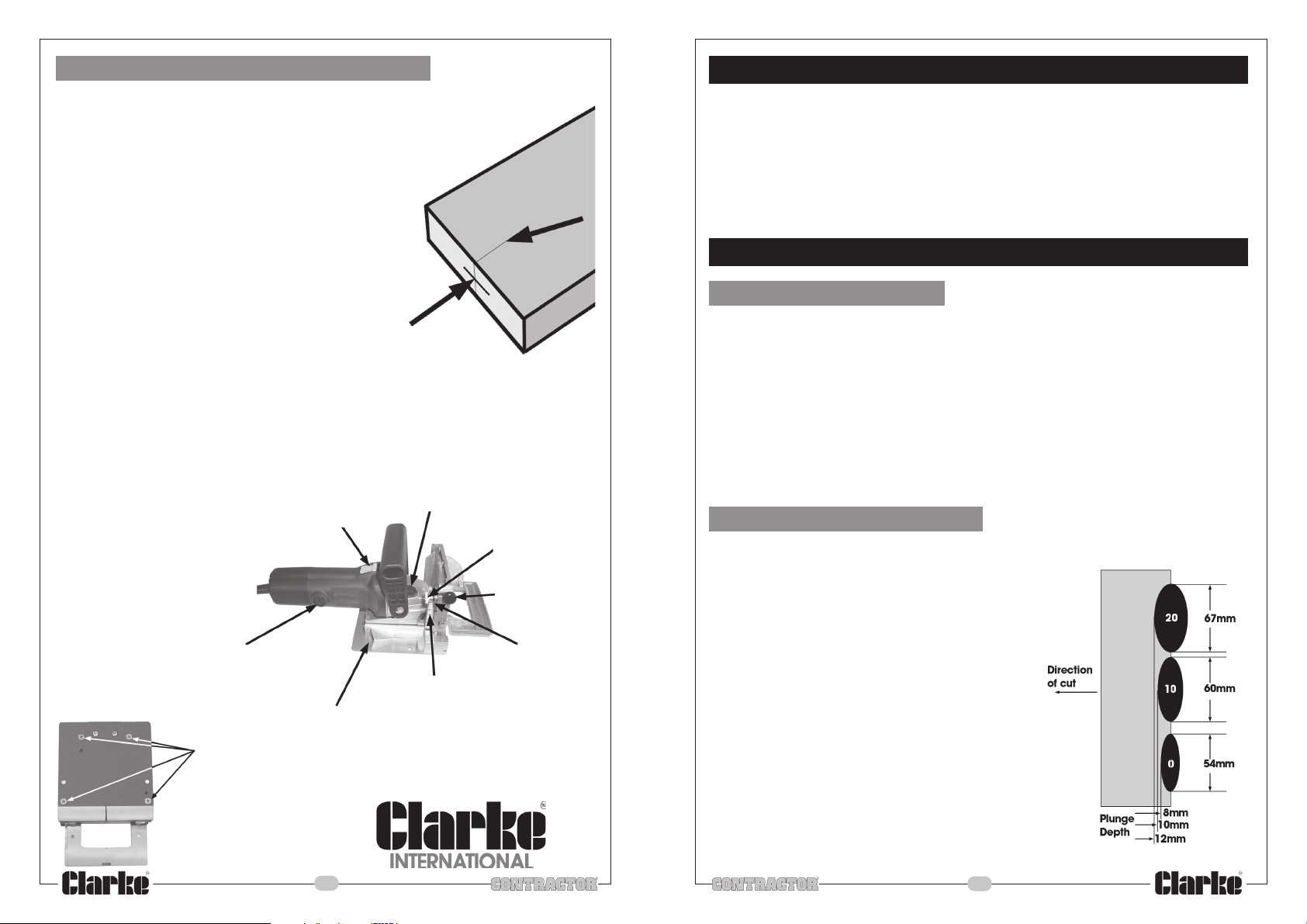
Making A Normal Biscuit Or Plate Joint
1. Position the mating pieces together and draw a reference mark (A) at 90º to the
centre point of each proposed joint location (B), space joints approx 100mm
apart.
2. Set the plunge depth to the biscuits you are using. generally #20
biscuits suit most applications. If you are using stock
15mm thick or less, you will require smaller biscuits.
3. Adjust the height of the fence as required.
4. Hold the tool by the handle with one hand and
support with the other hand on the motor body.
5. Rest the fence on the workpiece, line up the
centre point on the tool with the one marked
on the work.
6. Switch the tool on by sliding the ON/OFF switch
as far forwards as possible, latch in position by
pushing down on front of switch , (motor runs
continuously).
7. Maintaining a downward pressure on the fence, plunge the blade into the workpiece
by pushing the whole tool forwards up to the stop until the cut is complete.
8. Release the forward pressure and allow the tool to return so the blade is clear of
the workpiece. Switch the tool off by pushing down on the back of the ON/OFF switch,
(the switch will unlatch and the motor will stop).
9. Allow motor to stop before removing from workpiece and putting down.
ON/OFF Switch
Motor Brush
Dust Exhaust Port
Base Plate Screws
B
Blade Lock Button
Height Lock Knob
Fence Height
Adjusting Knob
Pointer
Fence Height Scale
Fig.3
A
Fig.4
ADDITIONAL PRECAUTIONS FOR BISCUIT JOINTERS
1. DO NOT lock the cover with the blade in the open position, always ensure it is
operating properly, freely returning to fully cover the blade teeth.
2. DO NOT stop the blade by applying lateral pressure on the side of the blade.
3. DO NOT use blades that do not comply with the specifications in this manual.
4. DO NOT use high speed steel (HSS) blades.
5. DO NOT use blades that are deformed or cracked etc.
ADJUSTMENTS
Adjustable Fence
ALWAYS switch the tool off, and remove from power supply, by removing the plug from the
socket, before making any adjustments.
The height of the fence can be adjusted to allow biscuit slots to be cut at varying depths
down the material. The adjustable tilt feature allows a full range of settings from 0º to 90º for
cutting slots on a mitred edge.
To adjust the height, first loosen the height lock knob (see Fig.3 page 11), rotate the knurled
adjusting knob (Fig.3 page 11) until the desired height is reached, use the scale and pointer
(Fig.3 page 11) to set height accurately. Tighten the height lock knob.
To adjust the angle of tilt, loosen the angle lock knob (Fig.2 page 10) move the fence until the
required angle is achieved, use the angle scale and pointer (Fig.2 page 10) to accurately
set the angle. Tighten the angle lock knob.
Plunge Depth Adjustment
The depth of cut can be set to match the dimensions of the particular size of biscuit used.
The numbers on the plunge depth adjusting knob
(Fig.2 page 10) (0-10-20) coincide with the three most
common biscuit sizes. The fourth position is marked with a
letter ‘M’, which stands for the maximum depth capacity
of the tool, (approximately 14mm).
To select the required depth, rotate the depth adjustment
knob, until it clicks into place at the appropriate number.
The width of a biscuit may vary between manufacturer’s.
The blade has been manufactured to allow fitment of
the largest biscuits in the slot cut. You may need to sort
out the correct sizes, and or moisten them to achieve a tight
fit.
Glue is applied and the biscuit inserted into the slot that is left
by the blade, the biscuit swells taking up any looseness in the
joint.
-11-
-8-
Page 10
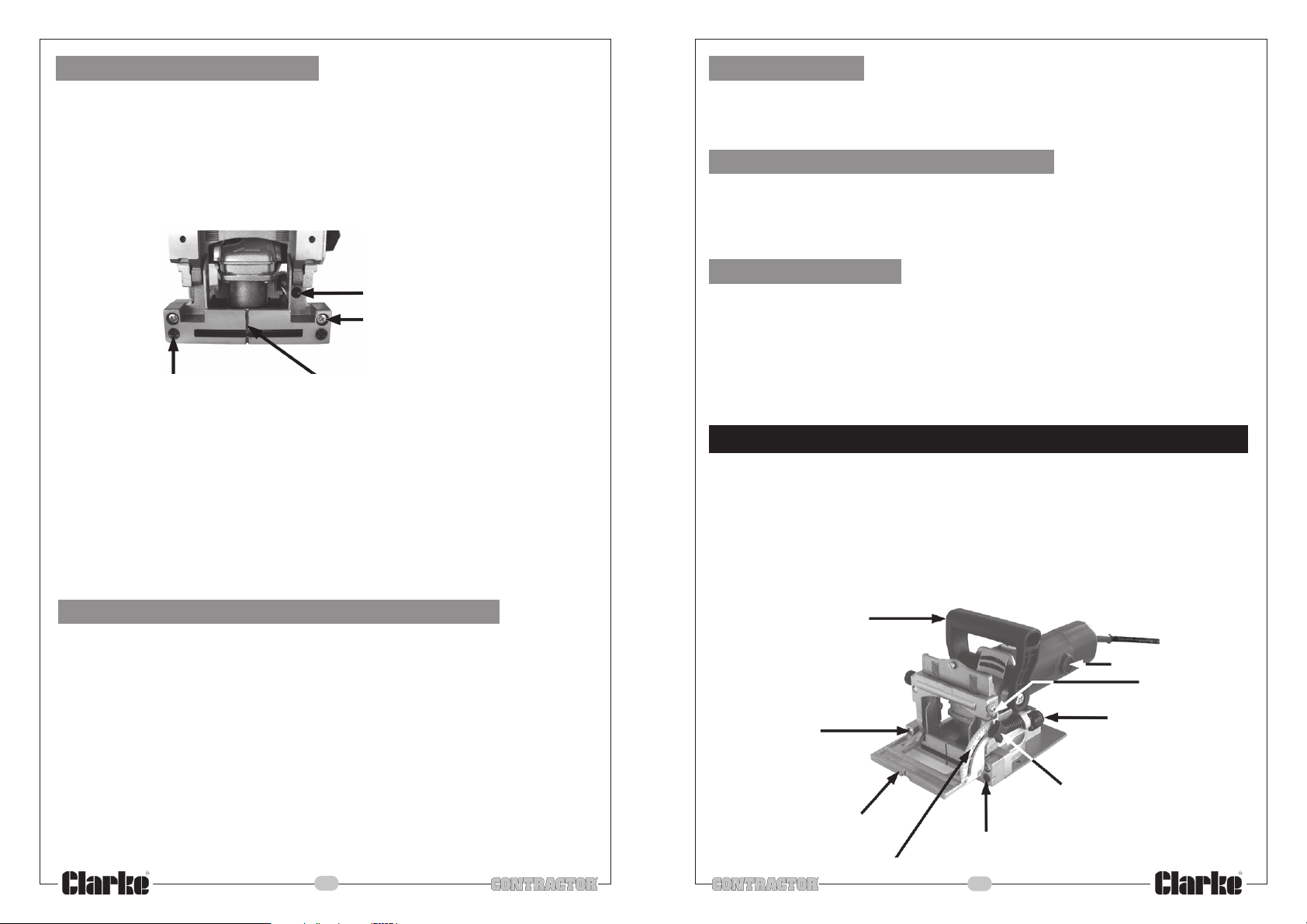
Fine Depth Adjustment
The depth settings (0-10-20-M) are fixed at 8,10,12 and 14mm respectively, these can be
increased to create a slight looseness in the joint to allow movement before the glue sets. To
carry out this adjustment, first raise the adjustable fence to its uppermost position, also set the
angle to ‘0’.
Insert pozidrive screwdriver into the hole, (see Fig.1), turn the depth adjustment screw
anticlockwise to increase the depth.
Each full turn increases the depth by 1mm. Always check the depth adjustment by first
making a test cut in a scrap piece of wood.
Depth Fine Adjusting Screw
Squareness Adjusting Screws
Fig.1
Grippers
Biscuit jointers tend to pull to the right when making a cut. Grippers have been provided to
reduce this effect. When making some joints. you may wish to retract the grippers so as not to
damage your workpiece . To prevent scratching rotate the grippers approximately ¼ turn
and push them back behind the front plate.
Adjusting The fence For Square
To adjust the fence for square, loosen the angle pointer screw (Fig.2), using a set square
between the fence and the front face of the tool. set the fence square, Place the indicator
against the stop on the 90º end of the angle scale and re-tighten the screw. check for square
again, if not square repeat adjustment until it is. When the angle indicator is against the stop
(pointer), the pointer should indicate 90º.
Bottom plate
For certain applications, you will want to use the bottom plate for alignment. In these cases,
the adjustable fence should be set at 0, the height setting is unimportant. This surface is used
primarily when making butt joints. The distance between the centerline of the blade and the
bottom plate is fixed at 9.5mm which allows centering on 19mm thick stock.
Grippers
NOTE:
This increased depth of cut is applied to all size settings (0-10-20-M), therefore it is
important to adjust back to standard if the extra depth is not required on the other sizes.
To get the maximum depth of cut possible, set the depth adjustment knob to ‘M’, then
turn the fine adjustment screw until the depth adjustment rod is completely loosened, this
will give a cutting depth of approximately 16mm, this depth may be required if using
home made biscuits or strips of wood, again the depth adjustment must be returned to
standard biscuit sizes when finished using the tool in this manner.
If the depth rod becomes loose and turns whilst using the tool. Either apply a thick grease
or a threadlock compound to the thread, either method will allow adjustment but prevents
further loosening due to vibration.
Centre Line
Adjusting The Blade Square With The Fence
The tool has been set up with the blade set up parallel to the fence. Check this has not
changed in shipping. Ensure the tool is switched off and isolated from the main power supply
by removing the plug from the socket, check that the blade moves freely and that all of the
fence functions and controls are operating correctly.
Find a square edge on a scrap piece of wood, set the depth control to ‘M’ (maximum)
and the fence set to 90º, machine a slot. Now measure the distance from the top of the
square edge down to the top of the right hand side of the slot, now measure the left hand
side. Both measurements should be identical. If not the fence can be adjusted by loosening
the two fence square adjusting screws (Fig.1 page 8), Adjust the fence up or down on one
side only keeping the block parallel to the base plate, once in position tighten both screws,
take another cut and check the blade now cuts parallel to the fence. When finished, if the
blade block protrudes over the base plate and you require the two to be parallel, undo
the four base plate screws (Fig.4 page 10) and add a packing of insulating tape to the side
that requires raising.
For most operations these two parts do not require to be perfectly parallel.
-9-
OPERATION
Biscuit jointers can be used for making various types of strong, accurate joints in timber or
wood sheeting ie; contiboard etc.
To cut the biscuit slot, the body of the jointer is plunged forwards towards the material..
By utilizing the various features of the tool, you can create a wide range of different types
of joints.
Always mark a reference line on workpiece to line up with centre line on machine (Fig.1
page 9), to ensure accurate biscuit placement.
Handle
Motor Brush
Pointer
Plunge Depth
Fence square
Adjusting Screws x 2
Fence
Fence Angle Scale
Fence Angle
Lock Knob
Grippers x 2
Fig.2
-10-
Adjusting Knob
 Loading...