

Page 1
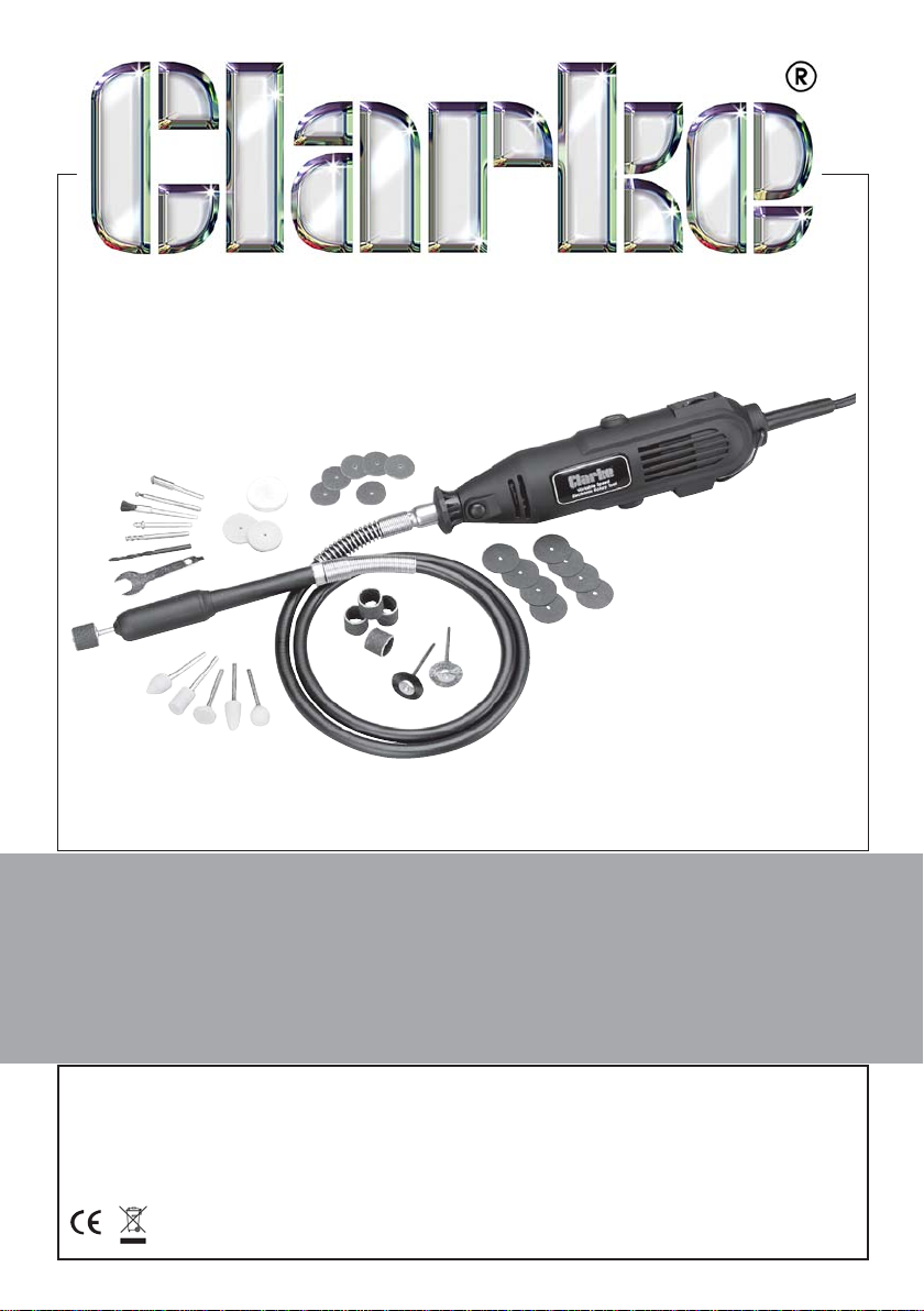
40-Piece Rotary Tool Kit
MODEL No: CRT40
Part Nos:6462001
USER INSTRUCTIONS
GC06/09
Page 2
INTRODUCTION
Thank you for purchasing this CLARKE 40-piece Rotary Tool Kit.
Please read this manual thoroughly and follow the instructions carefully. In
doing so you will ensure the safety of yourself and that of others around you,
and you can look forward to the product giving you long and satisfactory
service.
GUARANTEE
This product is guaranteed against faulty manufacture for a period of 12
months from the date of purchase. Please keep your receipt which will be
required as proof of purchase.
This guarantee is invalid if the product is found to have been abused or
tampered with in any way, or not used for the purpose for which it was
intended.
Faulty goods should be returned to their place of purchase, no product can
be returned to us without prior permission.
This guarantee does not effect your statutory rights.
ENVIRONMENTAL PROTECTION
Do not dispose of this product with general household waste. It must
be disposed of according to the laws governing Waste Electrical and
Electronic Equipment, at a recognised disposal facility.
DECLARATION OF CONFORMITY
We declare that this product conforms to the following directives:
98/37/EC
For Serial/Batch No: Please See Product Data Plate.
Signed:
2
Page 3

PACKAGE CONTENTS
The package contains:
1 Rotary Tool
1 Flexible Drive
1 Tool Stand Complete
1 Chuck spanner
37 Accessories/consumables
1 Case
SAFETY PRECAUTIONS
• ALWAYS keep the power cable away from the moving parts of the rotary
tool.
• ALWAYS switch off the tool and allow it to stop fully before putting it down.
• In the event of power failure or disconnection of supply for whatever
reason, when the tool is in operation...ALWAYS SWITCH OFF the tool before
putting it down, then disconnect it from the mains supply.
• ALWAYS ensure the accessories used are rated for rotation at the
maximum speed of the tool.
• NEVER attach an assembly wrench to your rotary tool with a piece of
string or anything similar.
• NEVER press the drive shaft locking button when the rotary tool is
operating.
• ALWAYS ensure that the mandrel diameter is the same as the collet
diameter.
• ALWAYS use a clamping device for securing the work piece. Keep your
hands away from the work piece.
• ALWAYS wear safety goggles, manufactured to the latest European Safety
Standards. Everyday eyeglasses do not have impact resistant lenses, they
are not safety glasses.
• NEVER force the tool, only light pressure is required to perform a task.
• NEVER overtighten the screw when mounting a grinding disc or cutting
disc onto its mandrel.
• NEVER allow children to operate this tool.
• IF the tool begins to vibrate during operation, switch OFF immediately and
investigate the cause.
3
Page 4

ELECTRICAL CONNECTIONS
This product is provided with a 13 amp BS 1363 plug, fitted with a 13amp fuse and
MUST be connected to a standard, 230 Volt (50Hz) electrical supply, preferably
through an approved plug, or a suitably fused isolator switch.
WARNING: THIS APPLIANCE MUST BE EARTHED
IMPORTANT: The wires in the mains lead should be wired up in accordance
with the following colour code:
Green & Yellow - Earth
Blue - Neutral
Brown - Live
As the colours of the flexible cable of this appliance may not correspond with
the coloured markings identifying terminals in your plug, proceed as follows:
•
Connect the GREEN & YELLOW coloured cord to the plug
terminal marked with a letter E or Earth symbol “
coloured GREEN or GREEN & YELLOW.
• Connect the BROWN coloured cord to the plug terminal
marked a letter “L” or coloured RED.
•
Connect the BLUE coloured cord to the plug terminal marked
a letter “N” or coloured BLACK
If this appliance is found to be fitted with a plug which is moulded on to the
electric cable (i.e. non-rewireable) please note:
1. The plug must be thrown away if it is cut from the electric cable. There is a
danger of electric shock if it is subsequently inserted into a socket outlet.
2. Never use the plug without the fuse cover fitted.
3. Should you wish to replace a detachable fuse carrier, ensure that the
correct replacement is used (as indicated by marking or colour code).
4. Replacement fuse covers can be obtained from your local Clarke dealer
or most electrical stockists.
” or
FUSE RATING
The fuse in the plug must be replaced with one of the same rating and this
replacement must be ASTA approved to BS1362.
We strongly recommend that this machine is connected to the mains supply
via a Residual Current Device (RCD).
4
Page 5
ASSEMBLY OF COMPONENTS
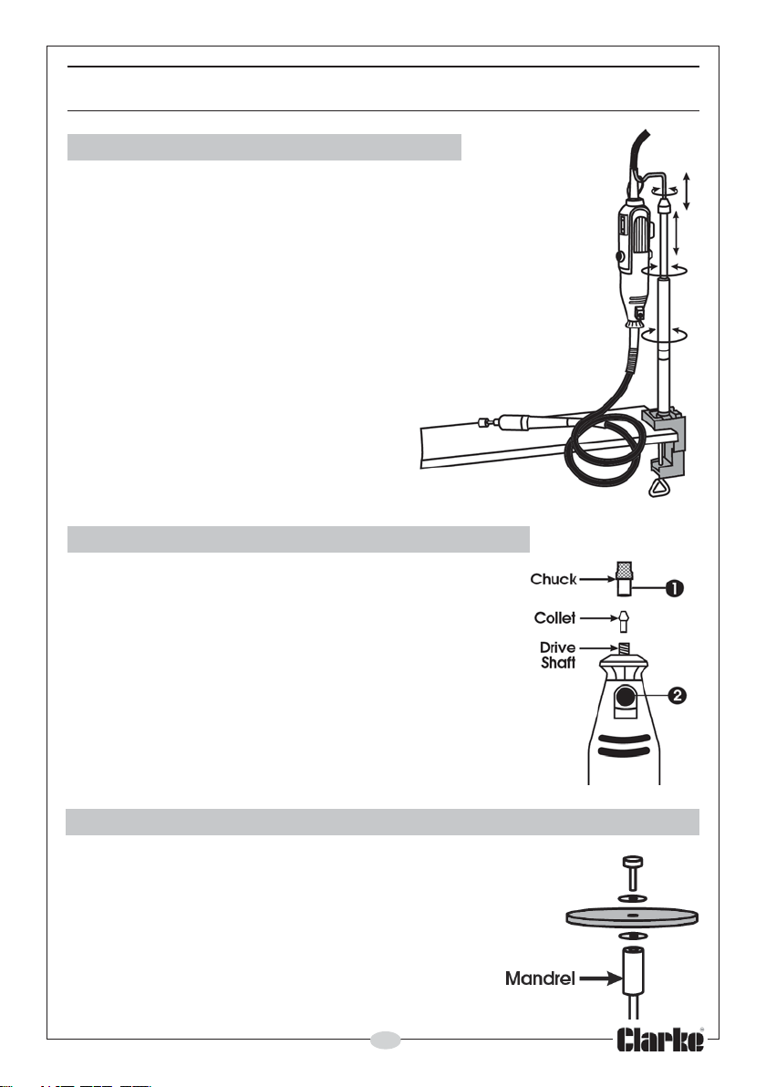
1. STAND FOR THE ROTARY TOOL
Screw the telescopic tube into the bracket and tighten.
Clamp the bracket to a workbench or worktop with a
maximum thickness at 2-1/8”.
Slacken the top tube by turning the black knob anticlockwise (-).
Draw the tube out to its maximum height and secure it by
turning the knob clockwise (+).
Turn the middle tube anticlockwise (-) and extend as required.
Lock in position by turning the tube clockwise (+).
The Rotary Tool can now be supported by the suspension
bracket of the stand as shown. (the suspension bracket
can be turned 360O).
2. ASSEMBLING ACCESSORIES TO THE TOOL
IMPORTANT: Ensure the tool is switched OFF at the
mains supply and at the tool switch.
• Press down on the drive shaft locking button (2),
and hold down.
• Undo the chuck (1) using the spanner provided.
• Insert the mandrel of the tool to be used in to the
chuck FULLY and tighten the chuck.
3. ASSEMBLING DISCS & GRINDING STONES TO THE MANDREL
• Mount the selected disc on to the mandrel as shown,
ensuring the two washers are in place.
DO NOT overtighten the screw.
5
Page 6
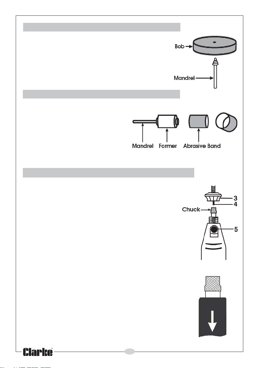
4. ASSEMBLING POLISHING BOB
• Screw the Bob on to the mandrel firmly, but do
not overdo it.
E
5. Assembling Abrasive Bands
• Slacken the screw on the end
of the mandrel and slide the
appropriate abrasive band on
to the rubber former, fully.
• Tighten the screw to secure
the band to the former.
6. ATTACHING THE FLEXIBLE DRIVE ASSEMBLY
• Unscrew and remove the Securing Ring (3) and
retain.
• Slacken the chuck using the spanner provided,
by pressing and holding the locking button (5).
• Slide the flexible drive through the chuck and
FULLY into the collet.
• Hold back the Securing Ring (3), whilst tightening
the chuck, thereby securing the flexible drive.
• Screw the Securing Ring (3) on to the end of the
tool, taking GREAT CARE to not to cross-thread it.
• At the opposite end of the Flexible Drive, insert
the mandrel of the tool to be used into the
chuck.
To undo the chuck, pull back on the sleeve in the
direction of the arrow and hold back to lock the drive
so that the spanner may be used.
Insert the mandrel fully, then re-tighten the
chuck.
Release the sleeve to release the drive.
6
Page 7
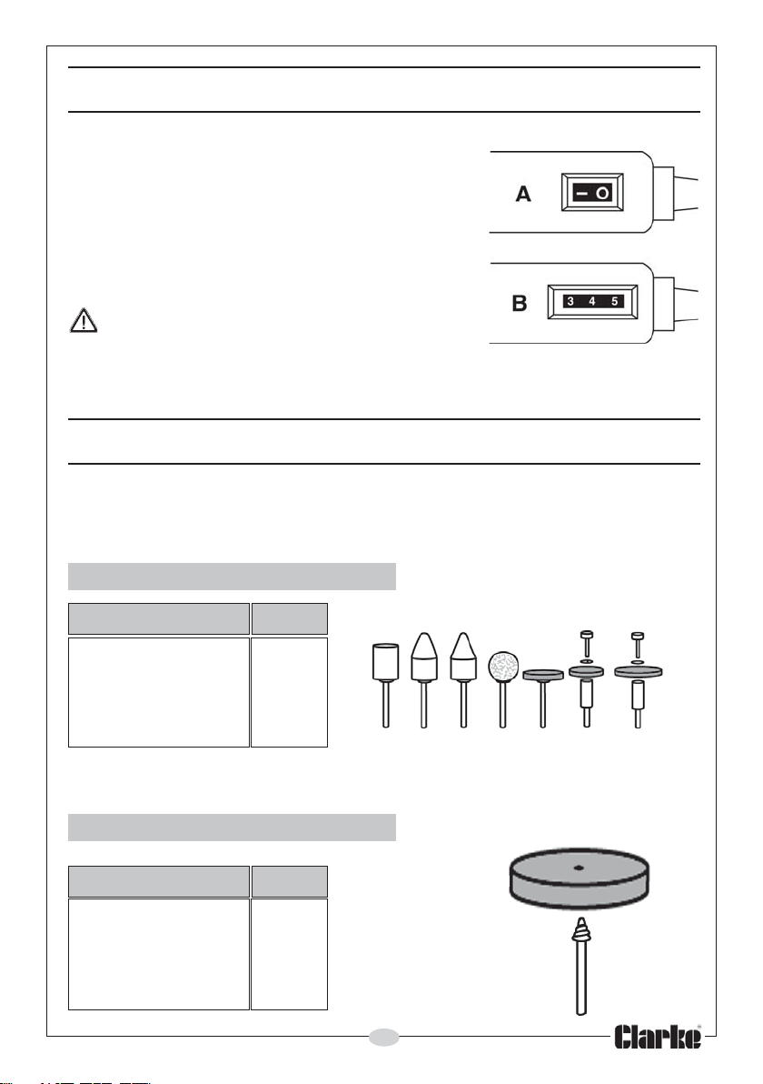
OPERATION
Assemble the tool as described previously.
Holding the tool firmly, and ensuring your fingers are
well away from the rotating parts, plug into the mains
and switch ON by pressing ‘I’ (A).
Adjust the speed according to the job in hand, by
turning the adjuster ‘B’, using the tables below for
reference.
To switch OFF, press ‘O’ (A).
CAUTION! NEVER put the tool down until it has
stopped completely.
DO NOT use force when using this tool; a light
pressure is all that is required.
REFERENCE TABLES
• The following speeds are for guidance only.
1. Grinding Stones
Material Speed
Stone, Shell 1
Steel 5
Aluminium, Brass 2
Plastic 1
2. Polishing Bob
Material Speed
Steel 5
Aluminium, Brass 3
Plastic 5
7
Page 8
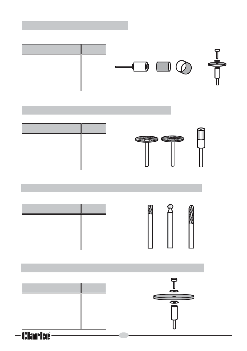
3. Sanding Band & Discs
Material Speed
Wood Max
Steel 1
Aluminium, Brass 3
Plastic 1
4. Stainless Steel Brushes & Bristle Brush
Material Speed
Stone, Shell 2
Aluminium, Brass 2
5. High Speed Cutter, Diamond Wheel & Drill
Material Speed
Stone, Shell Max
Steel 3
Aluminium, Brass 4
Plastic 1
6. Abrasive Disc
Material Speed
Stone, Shell Max
Steel 3
Aluminium, Brass 4
Plastic 1
8
Page 9
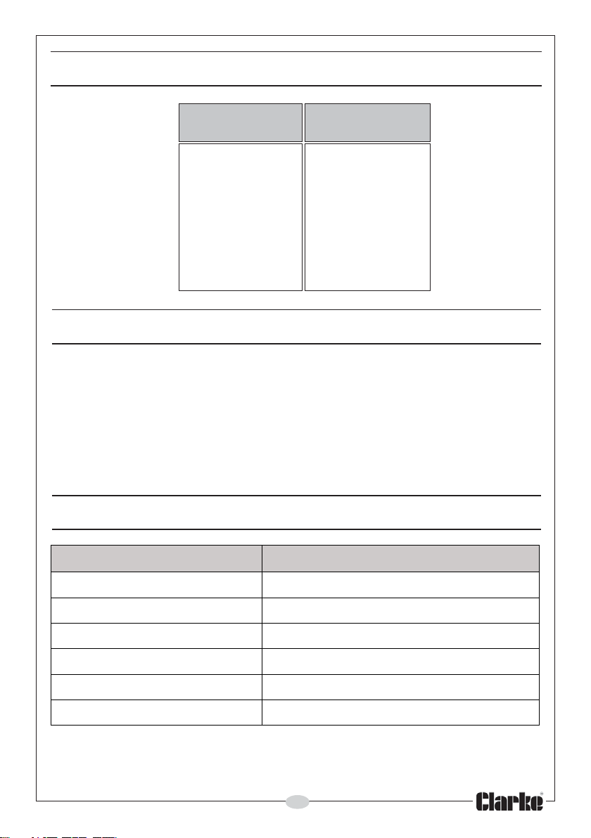
VARIABLE SPEED CHART
Speed Indicator
Position
1 17,500
2 18,500
3 24,500
4 27,800
5 31,000
MAX 35,000
RPM
MAINTENANCE
ALWAYS unplug the tool from the mains supply and ensure it is switched OFF when
performing maintenance tasks.
The tool should be kept clean at all times. Ensure the ventilation ducts are clear
and the power cable is in good condition. Get into the habit of cleaning thoroughly
after each use and before storing.
Never clean with solvents, use a moist cloth with soapy water if necessary.
The tool does not require lubrication.
TECHNICAL SPECIFICATION
metI noitacificepSdehsilbuP
egatloVhp1zH05V032
gnitaRrewoPW531
deepSdaol-oNmpr000,53-000,51
yticapaCtelloC"8/1
thgi
eW)dekcap(gk5.2
noitarbiVs/m5.2nahtsseL
Please note that the details and specifications contained herein, are correct
at the time of going to print. However, CLARKE International reserve the right
to change specifications at any time without prior notice.
9
2
Page 10
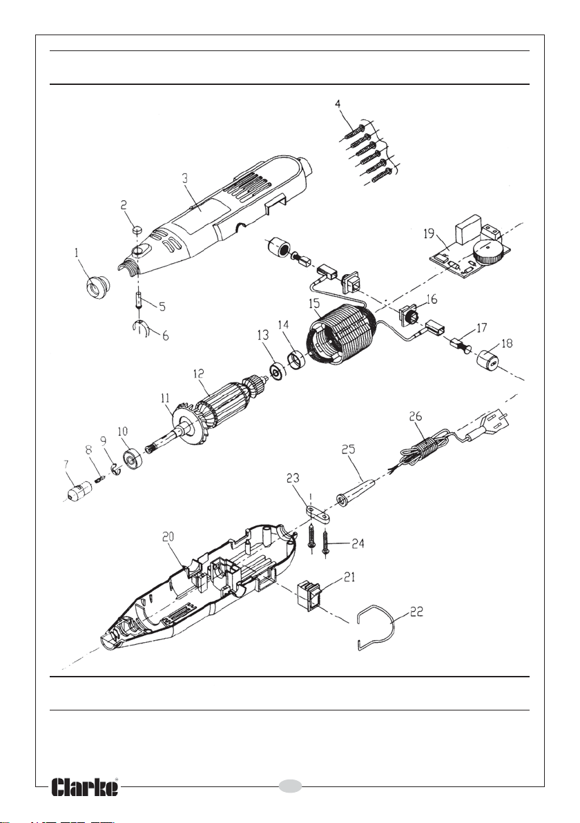
PARTS DIAGRAM
ACCESSORIES
A 100 piece Accessory Kit (CRT100A) is available from your Clarke dealer.
Please quote Part Number 6468025
10
Page 11

PARTS LIST
1 Head Cap.................................................................................. TMCT4001
2 Push Button ................................................................................ TMCT4002
3 Housing ...................................................................................... TMCT4003
5 Step Pin ...................................................................................... TMCT4005
6 Spring Ring ................................................................................. TMCT4006
7 Hex Nut ....................................................................................... TMCT4007
8 Collet .......................................................................................... TMCT4008
9 Clip Ring ..................................................................................... TMCT4009
10 BaIl Bearing ................................................................................ TMCT4010
11 Cooling Fan ............................................................................... TMCT4011
12 Armature .................................................................................... TMCT4012
13 Ball Bearing ................................................................................ TMCT4013
14 Stator .......................................................................................... TMCT4014
15 Brush Copper Sleeve ................................................................ TMCT4015
16 Brush Holder ............................................................................... TMCT4016
17 Carbon Brush ............................................................................. TMCT4017
18 Brush Cap .................................................................................. TMCT4018
19 Printed Circuit Board ................................................................ TMCT4019
20 Housing ...................................................................................... TMCT4020
21 Switch ......................................................................................... TMCT4021
22 Hook ........................................................................................... TMCT4022
23 Cable Anchorage .................................................................... TMCT4023
24 Screw .......................................................................................... TMCT4024
25 Cable Sleeve ............................................................................ TMCT4025
26 Plug & Cable ............................................................................. TMCT4026
SPARE PARTS AND SERVICE CONTACTS
For parts & Servicing, please contact your nearest dealer, or
CLARKE International, on one of the following numbers.
PARTS & SERVICE TEL: 020 8988 7400
PARTS & SERVICE FAX: 020 8558 3622
or e-mail as follows:
PARTS: [email protected]
SERVICE: [email protected]
11
Page 12

 Loading...