

Page 1
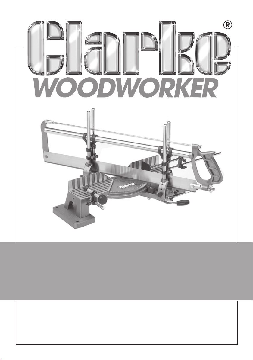
COMPOUND MITRE SAW
MODEL NO: MBS600C
Part No: 6461512
ASSEMBLY INSTRUCTIONS
GC0311
Page 2

INTRODUCTION
Thank you for purchasing this CLARKE Mitre Saw.
Before attempting to use the product, it is essential that you read this manual
thoroughly and carefully follow all instructions given. In doing so you will
ensure the safety of yourself and that of others around you, and you can also
look forward to the product giving you long and satisfactory service.
GUARANTEE
This CLARKE product is guaranteed against faulty manufacture for a period of
12 months from the date of purchase. Please keep your receipt as proof of
purchase.
This guarantee is invalid if the product is found to have been abused or
tampered with in any way, or not used for its intended purpose.
Faulty goods should be returned to their place of purchase, no product can
be returned to us without prior permission. This guarantee does not effect
your statutory rights.
ENVIRONMENTAL PROTECTION
Do not dispose of this product with general household waste. All tools,
accessories and packaging should be sorted, taken to a re-cycling centre
and disposed of appropriately.
SERVICING
For parts & servicing, please contact your nearest dealer, or
CLARKE International, on one of the following numbers.
PARTS & SERVICE TEL: 020 8988 7400
PARTS & SERVICE FAX: 020 8558 3622
or e-mail as follows:
PARTS: [email protected]
SERVICE: [email protected]
2
Parts & Service: 020 8988 7400/E-mail:[email protected] or [email protected]
Page 3
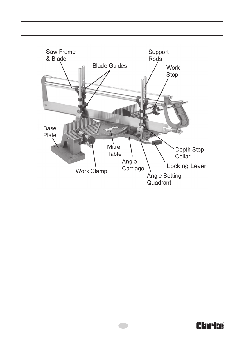
COMPONENT GUIDE
FIG 1
Upon receipt of the product, unpack all loose components and check for
any missing parts. Any identified should be reported to your Clarke dealer.
The MBS600C includes the following:
1 x Saw Frame c/w Blade
1 x Mitre Table
2 x Base Plates
1 x Angle Carriage
4 x Support Rods
1 x Work Clamp
1 x Work Stop
1 x Fixings Pack containing: Pointer & screw,
Pivot Pin,
4 x screws/washers,
4 x Depth Stop Collars.
3
Parts & Service: 020 8988 7400/E-mail: [email protected] or [email protected]
Page 4
ASSEMBLY
BASE PLATES
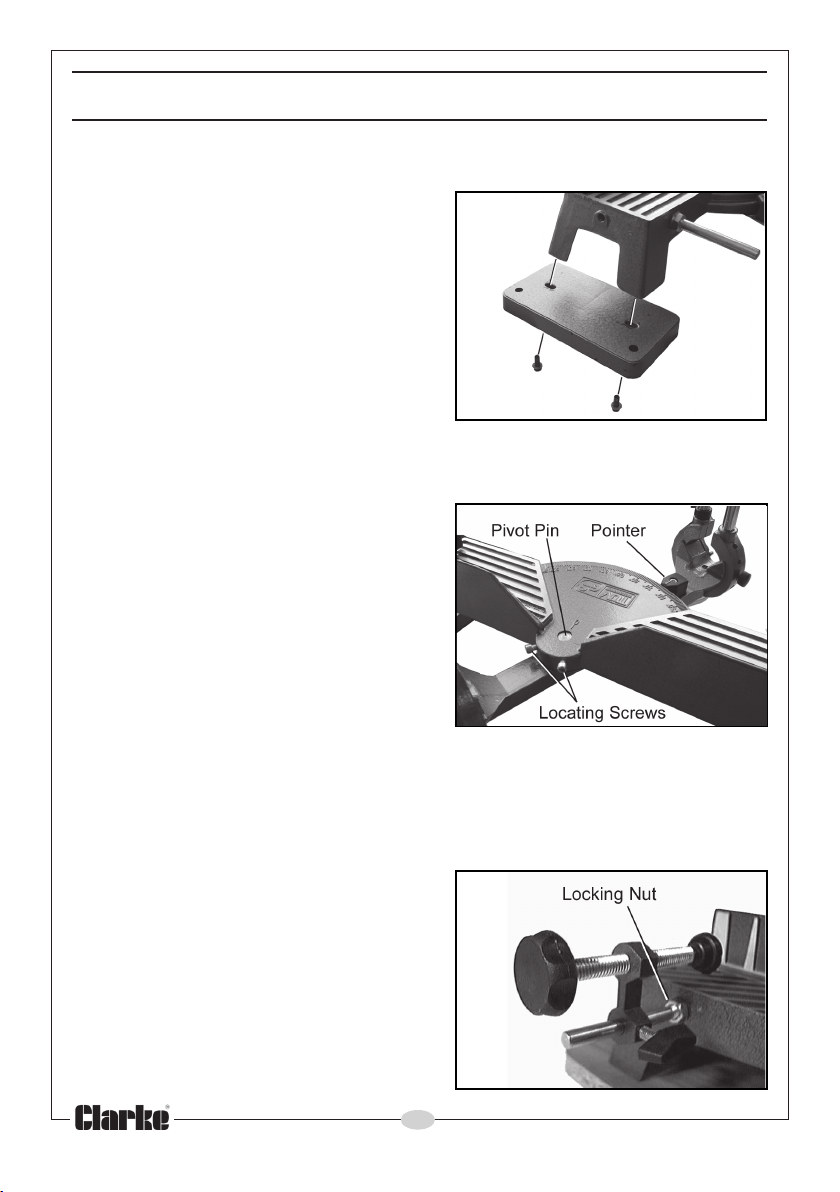
Attach the Base Plates to the Mitre Table
using the socket head screws and flat
washers provided - two for each base.
• A 3mm hex key is required.
• The two holes nearer the edge of the
base should be towards the outside
of the Mitre Table and are visible
when assembled as shown in Fig 2.
• These holes may be used to fix the
Mitre Saw to a workbench for
additional stability (see Mounting).
MITRE TABLE
Attach the Angle Carriage to the Mitre
Table. Line up the pivot hole in the angle
carriage with the hole in the Mitre Table
and insert the pivot pin from below as
shown in Fig 3. Lift the locking lever,
depressing the locking pin so that the
angle carriage and table can connect.
• The pivot pin is a tight fit so it may be
necessary to turn the table over and
tap it home with a small hammer.
Screw in the two locating screws as shown in Fig 3, and tighten
with a 3mm hex key allowing the carriage to move freely on the pin,
but without any slop between the carriage and the table.
Attach the Pointer to the carriage with the screw provided as shown in Fig 3.
FIG 2
FIG 3
WORK CLAMP
Screw the Work Clamp support into one
of the threaded holes in the front face of
the Mitre Table, (see fig 4), depending
upon which side of the saw blade your
work is to be mounted.
Secure the Work Clamp support with the
locking nut.
4
Parts & Service: 020 8988 7400/E-mail:[email protected] or [email protected]
FIG 4
Page 5
GUIDE RODS, SAW FRAME AND BLADE
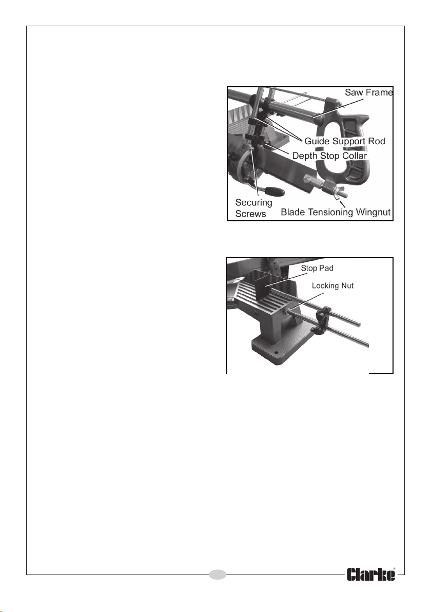
Insert the Guide Support Rods into the holes in each angle setting quadrant
as shown in Fig. 5 and secure using the x-head screws.
Slide a Depth Stop Collar onto either
one of the Guide Support Rods at each
end of the carriage, before carefully
sliding the guides of the Saw Frame
Assembly onto the Guide Support Rods.
With the Saw Frame assembly in
position, tension the blade using the
wing nut, until any sideways deflection
of the blade is minimal.
• This is essential to ensure a straight
and repeatable cut from the blade.
WORK- STOP
FIG 5
Screw the Stop Support Rod into the
threaded hole at one end of the Mitre
Table depending upon which side of
the saw blade your work is to be
mounted.
Position the stop pad close to the table
surface and lock the rod in place with
the locking nut as shown in Fig 6.
• Your Mitre Saw is now fully
assembled and ready for use.
MOUNTING
FIG 6
You may wish to install the Mitre Saw on a firm foundation such as a
workbench or work table. This is particularly advisable if you are cutting larger
workpieces.
Use the holes in the Base Plates for this purpose, securing with bolts, flat
washers and wing nuts for quick and easy removal, if required (not supplied).
5
Parts & Service: 020 8988 7400/E-mail: [email protected] or [email protected]
Page 6
USING THE MITRE SAW
CUTTING SIMPLE MITRES OR BEVELS
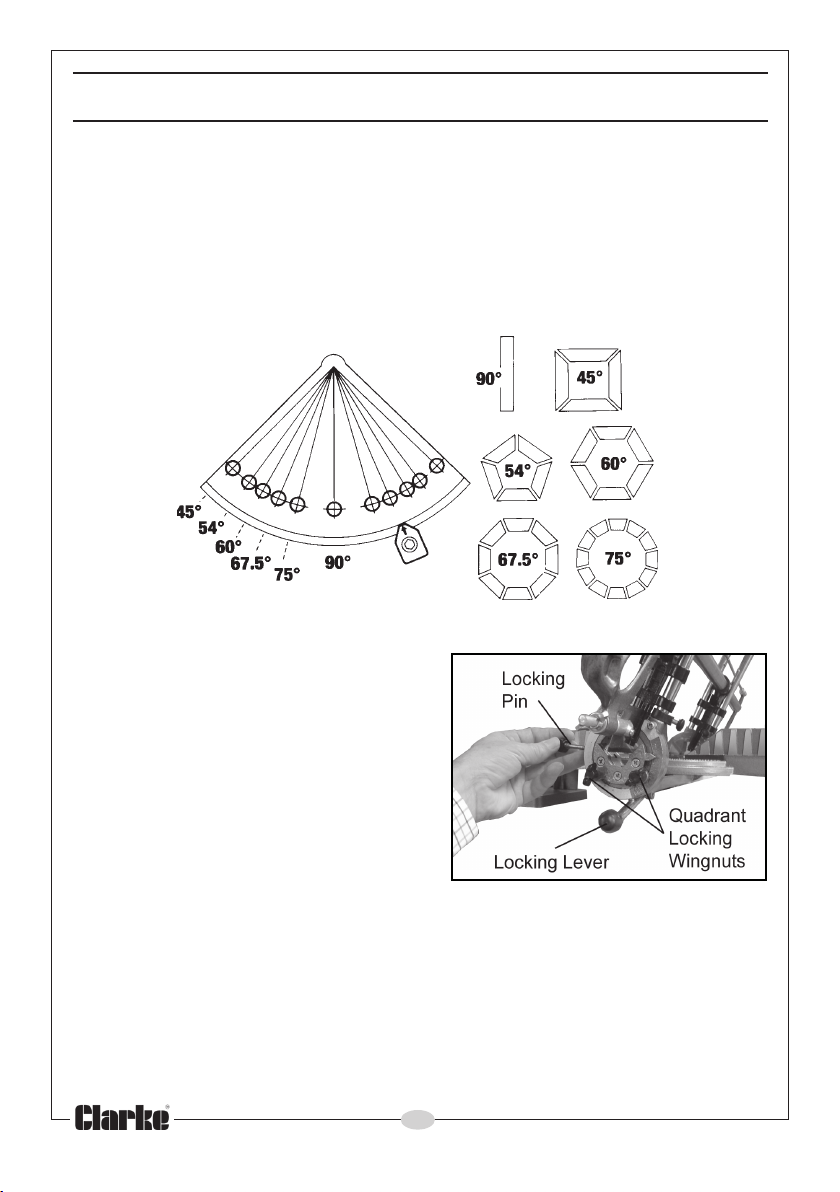
Simple mitres or bevels are cuts made in one plane only. For simple mitres, the
carriage is moved to the desired angle to the base by lifting the Locking
Lever to allow the carriage to swivel, with the saw blade remaining
perpendicular to the table.
Setting the Carriage to the angles shown in Fig 7, will produce the mitres
illustrated. The angle is shown by the pointer.
FIG 7
COMPOUND MITRES
For compound mitres the saw frame is
tilted over at an angle to the table. This
is done by removing the Locking Pin
and slackening off the Quadrant
Locking Wingnuts sufficiently to free the
Quadrant and to allow the Saw Frame
to be tilted to the desired angle. The
locking pin is then replaced and the
wingnuts re tightened (Fig 8), when the
Saw Frame is set at the desired angle.
Compound mitres are therefore cut
using a combination of these settings.
FIG 8
CUTTING TECHNIQUE
When cutting, DO NOT force the saw blade, as this will lead to blade
distortion and inaccurate mitres/bevels. Only a very gentle pressure is
required. Let the saw do the work.
Ensure the Locking Pin is in place and the Quadrant Locking Wingnuts at both
ends of the carriage are tight before use.
6
Parts & Service: 020 8988 7400/E-mail:[email protected] or [email protected]
Page 7
Ensure the saw blade is correctly tensioned before use - too slack will allow
the blade to twist, producing inaccurate mitres.
Use the Depth Stop Collars as required when making either a horizontal or
sloping cut. Tighten them securely with the thumbscrews before cutting.
MAINTENANCE
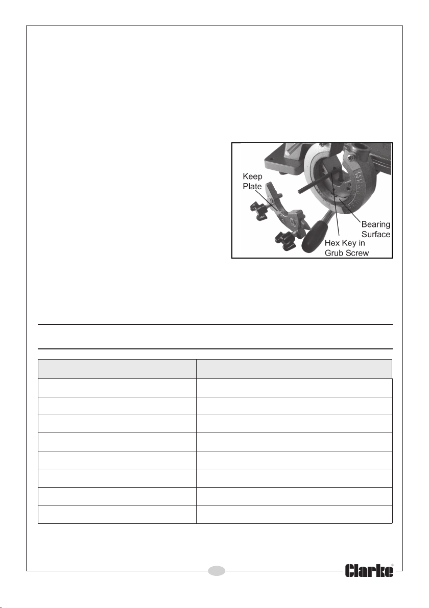
Should the rotating movement of the quadrants become sticky, unscrew the
keep-plate of each quadrant to allow its removal.
Pull the quadrant forward and capture
the ball and spring which will fall out,
Clean the castings of any sawdust and
apply a light coating of general purpose
grease to the quadrant mating surfaces
before re-assembly.
• Note that the ball and spring can be
re-fitted either from below, or from
above, through the grub screw hole
shown in Fig 9. The spring tension can
be adjusted by tightening the grub
screw with a hex key.
Replacement Blades are available from your CLARKE dealer;
Part No: 6470175
FIG 9
SPECIFICATIONS
erutaeF noitacificepS
htdiWesaBmm584
htgneLelbaTmm004
htgneLedalBwaSmm006
htpeDedalBwaSmm54
thgieWgk0.4
tuCfohtpeDxaMmm02
O
09@tuCfohtdiWxaM
hcnIrephteeTipt41
Please note that the details and specifications contained herein, are correct at the
time of going to print. However, CLARKE International reserve the right to change
specifications at any time without prior notice.
Parts & Service: 020 8988 7400/E-mail: [email protected] or [email protected]
1
mm09
7
Page 8

 Loading...