

Page 1
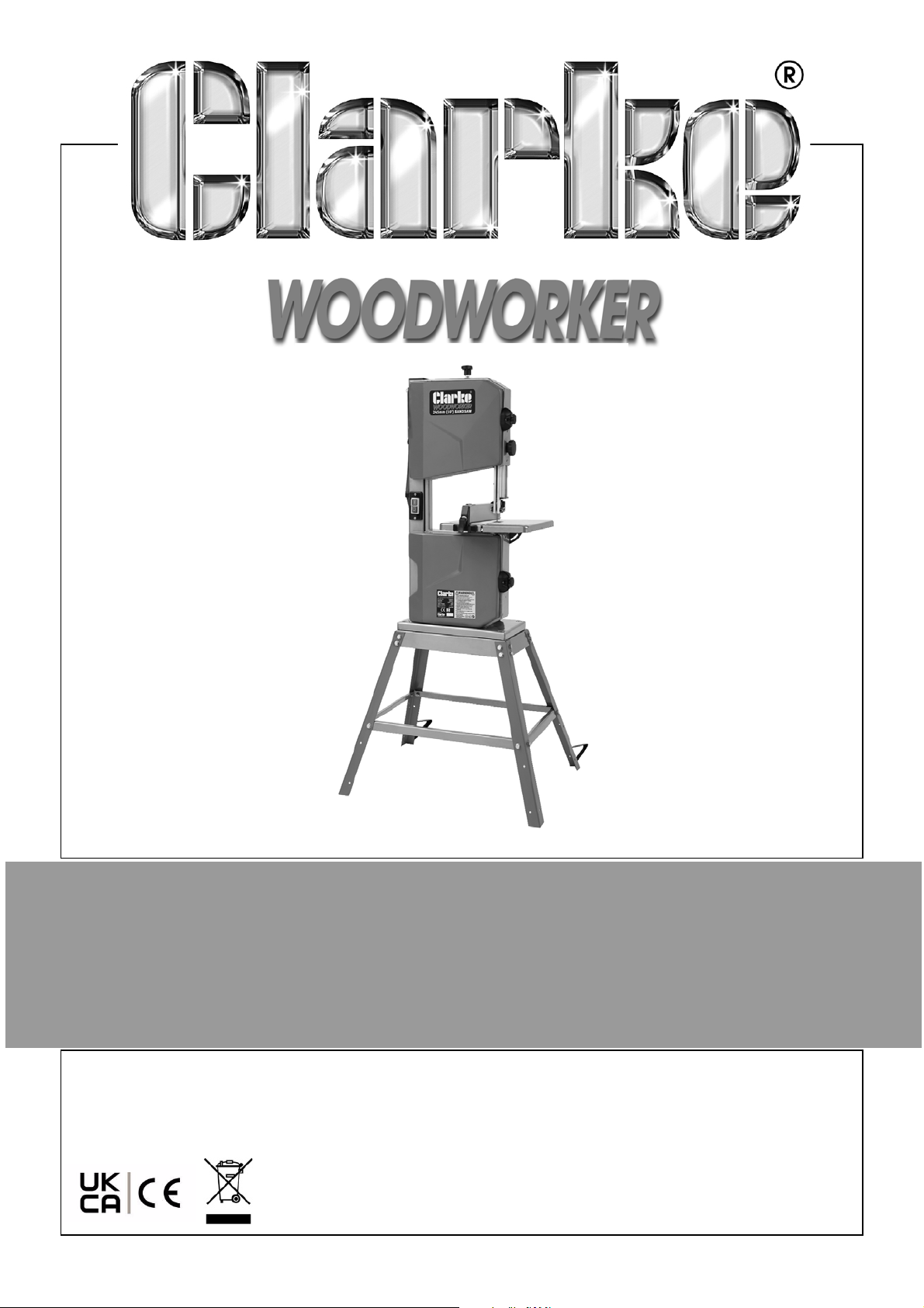
250MM BANDSAW WITH STAND
MODEL NO: CBS250C
PART NO: 6460141
OPERATION & MAINTENANCE
INSTRUCTIONS
ORIGINAL INSTRUCTIONS
DL1221 - REV2
Page 2
INTRODUCTION
Thank you for purchasing this CLARKE 250mm Bandsaw with stand.
Before attempting to operate the machine, it is essential that you read this
manual thoroughly and carefully follow all instructions given.
GUARANTEE
This CLARKE product is guaranteed against faulty manufacture for a period of
12 months from the date of purchase. Please keep your receipt as proof of
purchase.
This guarantee is invalid if the product is found to have been abused or
tampered with in any way, or not used for the purpose for which it was
intended.
Faulty goods should be returned to their place of purchase, no product can
be returned to us without prior permission.
This guarantee does not affect your statutory rights.
ENVIRONMENTAL PROTECTION
Through purchase of this product, the customer is taking on the
obligation to deal with the WEEE in accordance with the WEEE
regulations in relation to the treatment, recycling & recovery and
environmentally sound disposal of the WEEE.
In effect, this means that this product must not be disposed of with general
household waste but according to the laws governing Waste Electrical and
Electronic Equipment (WEEE) at a recognised disposal facility.
2
Parts & Service: 020 8988 7400 / E-mail: [email protected] or [email protected]
Page 3

SAFETY PRECAUTIONS
WARNING: WHEN USING ELECTRIC TOOLS BASIC SAFETY PRECAUTIONS
SHOULD ALWAYS BE FOLLOWED TO REDUCE THE RISK OF FIRE, ELECTRIC
SHOCK AND PERSONAL INJURY INCLUDING THE FOLLOWING. READ ALL
THESE INSTRUCTIONS BEFORE ATTEMPTING TO OPERATE THIS PRODUCT
AND SAVE THESE INSTRUCTIONS
1. Keep work area clear
• Cluttered areas and benches invite injuries.
2. Consider work area environment
• DO NOT expose tools to rain.
• DO NOT use tools in damp or wet locations.
• Keep work area well lit.
• DO NOT use tools in the presence of flammable liquids or gases.
3. Guard against electric shock
• AV O ID body contact with earthed or grounded surfaces (e.g. pipes,
radiators, ranges, refrigerators).
4. Keep other persons away.
• DO NOT let persons, especially children, not involved in the work touch
the tool or the extension lead and keep them away from the work area.
5. Store idle tools
• When not in use, tools should be stored in a dry locked-up place, out of
reach of children.
6. DO NOT force the tool
• It will do the job better and safer at the rate for which it was intended.
7. Use the right tool
• DO NOT force small tools to do the job of a heavy duty tool.
• DO NOT use tools for purposes not intended.
• Dress properly, DO NOT wear loose clothing or jewellery, they can be
caught in moving parts.
• Non-skid footwear is recommended when working outdoors.
• Wear protective hair covering to contain long hair.
8. Use personnel protective equipment
3
Parts & Service: 020 8988 7400 / E-mail: [email protected] or [email protected]
Page 4

• Use safety glasses.
• Use ear protection
•Use gloves
• Use face or dust mask if working operations create dust
9. Connect dust extraction equipment
• The tool is provided with a connection for dust extraction and collecting
equipment, ensure these are connected and properly used.
10. DO NOT abuse the power cable
• NEVER yank the power cable to disconnect it from the socket. Keep the
power cable away from heat, oil and sharp edges.
11. Secure work
• Where possible use clamps or a vice to hold the work. It is safer than
using your hand.
12. DO NOT overreach
• Keep proper footing and balance at all times.
13. Maintain tools with care
• Keep cutting tools sharp and clean for better and safer performance.
• Follow instruction for lubricating and changing accessories.
• Inspect the tool power cable periodically and if damaged have it
repaired by a CLARKE service facility.
• Inspect extension cabling periodically and replace if damaged.
• Keep handles dry, clean and free from oil and grease.
14. Disconnect tools
• When not in use, before servicing and when changing accessories such
as blades, bits and cutters, disconnect tools from the power supply.
15. Remove adjusting keys and wrenches
• Form the habit of checking to see that keys and adjusting wrenches are
removed from the tool before turning it on.
16. AV OI D unintentional starting
• Ensure switch is in the “off” position when plugging in.
17. Stay alert
• Watch what you are doing, use common sense and DO NOT operate
the tool when you are tired or under the influence of drugs or alcohol.
18. Check damaged parts
4
Parts & Service: 020 8988 7400 / E-mail: [email protected] or [email protected]
Page 5

• Before further use of the tool, it should be carefully checked to
determine that it will operate properly and perform its intended
function.
• Check for alignment of moving parts, binding of moving parts,
breakage of parts, mounting and any other conditions that may affect
its operation.
• A guard or other part that is damaged should be properly repaired or
replaced by a CLARKE service centre.
• Have defective switches replaced by a CLARKE service centre.
• DO NOT use the tool if the switch does not turn it on and off.
19. WARNING
• The use of any accessory or attachment other than one recommended
in this instruction manual may present a risk of personal injury.
20. Have your tool repaired by a CLARKE service centre.
• This electric tool complies with the relevant safety rules. Repairs should
only be carried out by qualified persons using original spare parts,
otherwise this may result in considerable danger to the user.
ADDITIONAL
1. Position the fence on the lower side of the table when bevel-cutting with
the table inclined;
2. Use a suitable holding device when cutting round or irregular shaped
timber to prevent twisting of the work piece;
3. DO NOT use saw blades which are damaged or deformed;
4. DO NOT override the lockout and operate the tool, when the guards
protecting the saw blade is open;
5. DO NOT clean the saw blade whilst it is moving;
6. ALWAYS wear gloves for handling the saw blade and rough material.
7. The push-stick should be used if the distance between the blade and rip
fence is less than approx 150 mm.
5
Parts & Service: 020 8988 7400 / E-mail: [email protected] or [email protected]
Page 6
ELECTRICAL CONNECTIONS
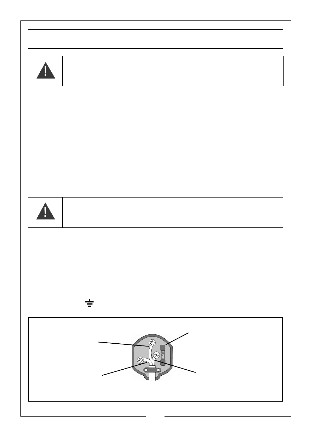
Plug must be BS1363/A approved.
Always fit a 5 Amp fuse.
Ensure that the outer sheath of the cable is firmly held by the clamp
Neutral
(Blue)
Live
(Brown)
Earth
(Green and Yellow)
WARNING! Read these electrical safety instructions thoroughly
before connecting the product to the mains supply.
Before switching the product on, make sure that the voltage of your electricity
supply is the same as that indicated on the rating plate. This product is
designed to operate on 230VAC 50Hz. Connecting it to any other power
source may cause damage.
This product may be fitted with a non-rewireable plug. If it is necessary to
change the fuse in the plug, the fuse cover must be refitted. If the fuse cover
becomes lost or damaged, the plug must not be used until a suitable
replacement is obtained.
If the plug has to be changed because it is not suitable for your socket, or due
to damage, it should be cut off and a replacement fitted, following the wiring
instructions shown below. The old plug must be disposed of safely, as insertion
into a mains socket could cause an electrical hazard.
WARNING! The wires in the power cable of this product are
coloured in accordance with the following code:
Blue = Neutral Brown = Live Yellow and Green = Earth
If the colours of the wires in the power cable of this product do not correspond
with the markings on the terminals of your plug, proceed as follows.
•The Blue wire must be connected to the terminal which is marked N or
coloured Black.
•The Brown wire must be connected to the terminal which is marked L or
coloured Red.
•The Yellow and Green wire must be connected to the terminal which is
marked E or coloured Green.
.
Parts & Service: 020 8988 7400 / E-mail: [email protected] or [email protected]
6
Page 7
We strongly recommend that this machine is connected to the mains supply via
a Residual Current Device (RCD)
If in any doubt, consult a qualified electrician. DO NOT attempt any repairs
yourself.
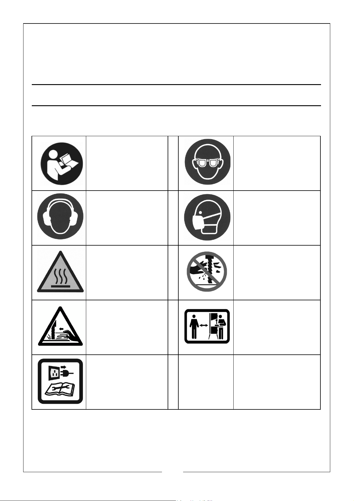
SAFETY SYMBOLS
Read the manual
and safety
instructions before
use
Ear protection
should be worn
WARNING, Motor
gets hot
WARNING, Risk of
injury, use push stick
were possible
Eye protection
should be worn
Dust mask should be
worn
Do not touch moving
blade
Keep children and
bystanders at a safe
distance
Disconnect from
power source
before
maintenance or
repair
7
Parts & Service: 020 8988 7400 / E-mail: [email protected] or [email protected]
Page 8
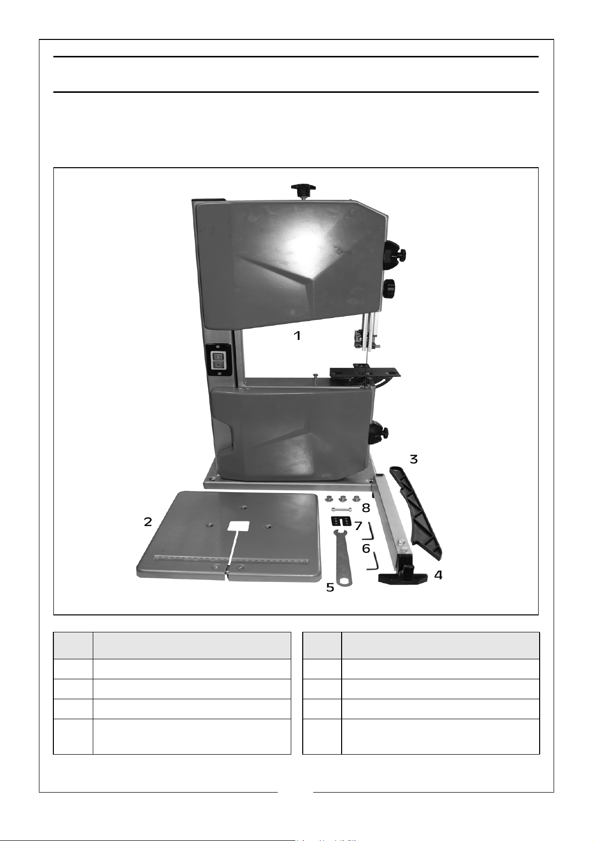
CONTENTS - BANDSAW
Make sure that all parts are un-damaged and are present. If any parts are
missing or damaged please contact your CLARKE dealer immediately.
The following loose components are supplied with the bandsaw assembly.
ITEM DESCRIPTION ITEM DESCRIPTION
1 Bandsaw Assembly 5 Spanner
2 Table 6 Allen Keys (3mm & 4mm)
3 Push Stick 7 Table Insert
4 Parallel Rip Fence Assembly 8 3 x M6 x 16 Bolt, Washer & Nut
1 x M6 x 35 Bolt & Nut
8
Parts & Service: 020 8988 7400 / E-mail: [email protected] or [email protected]
Page 9
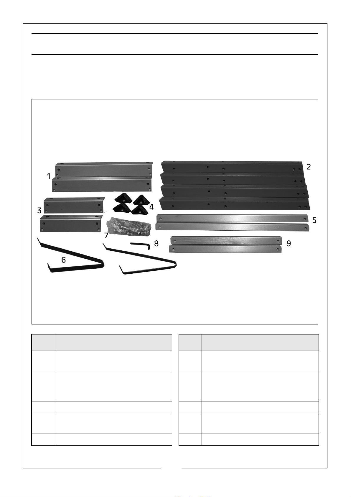
CONTENTS - STAND
Make sure that all parts are un-damaged and are present. If any parts are
missing or damaged please contact your CLARKE dealer immediately.
The following loose components are supplied with the stand assembly.
ITEM DESCRIPTION ITEM DESCRIPTION
1 2 x Long Beam - 400mm 6 2 x Assisted Support Leg -
190mm x 260mm
2 4 x Stand Legs - 560mm 7 24 x M8 x 16 Bolt, Washer & Nut
4 x M6 x 16 Bolt, Washer & Nut
4 x M8 x 45 Bolt, Washer & Nut
3 2 x Short Beam - 230mm 8 Allen Key (5mm)
4 4 x Rubber Feet 9 2 x Short Support Plate - 400mm
5 2 x Long Support Plate - 570mm
9
Parts & Service: 020 8988 7400 / E-mail: [email protected] or [email protected]
Page 10
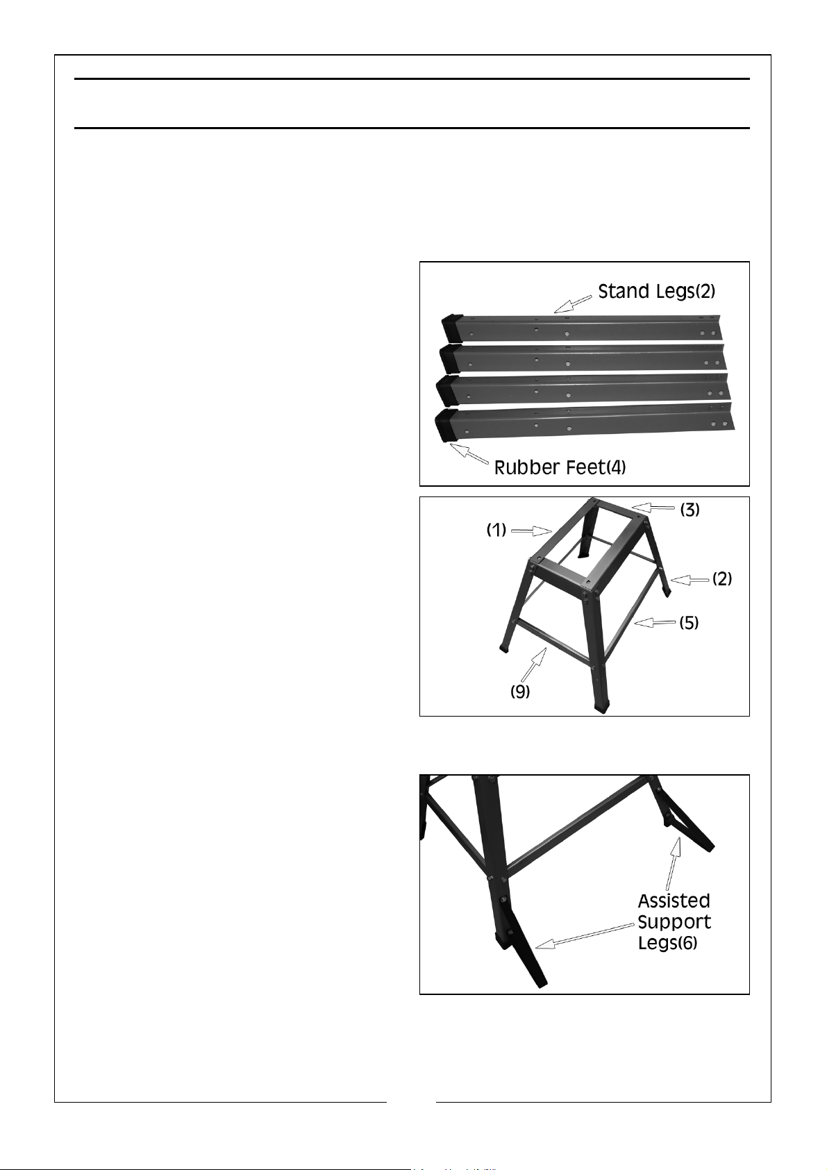
ASSEMBLY
ASSEMBLE THE STAND
NOTE: All numbers in brackets correspond to the Contents - Stand list on
page 9.
1. Place the rubber feet (4) onto the
ends of the stand legs (2).
2. Attach the 4 stand legs (2) to the
outside of the 2 long beams (1) &
2 short beams (3), securing each
leg with 4 x M8 x 16 bolts, flat
washers and nuts. Hand tighten
nuts only at this stage.
3. Attach the 2 long support plates
(5) and 2 short support plates (9)
to the legs, secure each with 2 x
M8 x 16 bolts, flat washers and
nuts. Hand tighten nuts only at this
stage.
4. Attach the 2 assisted support legs
(6) to the 2 stand legs (2) on the
long support plate (5) side of the
stand, secure each with 2 x M6 x
16 bolts, flat washers and
nuts.Hand tighten nuts only at this
stage.
10
Parts & Service: 020 8988 7400 / E-mail: [email protected] or [email protected]
Page 11
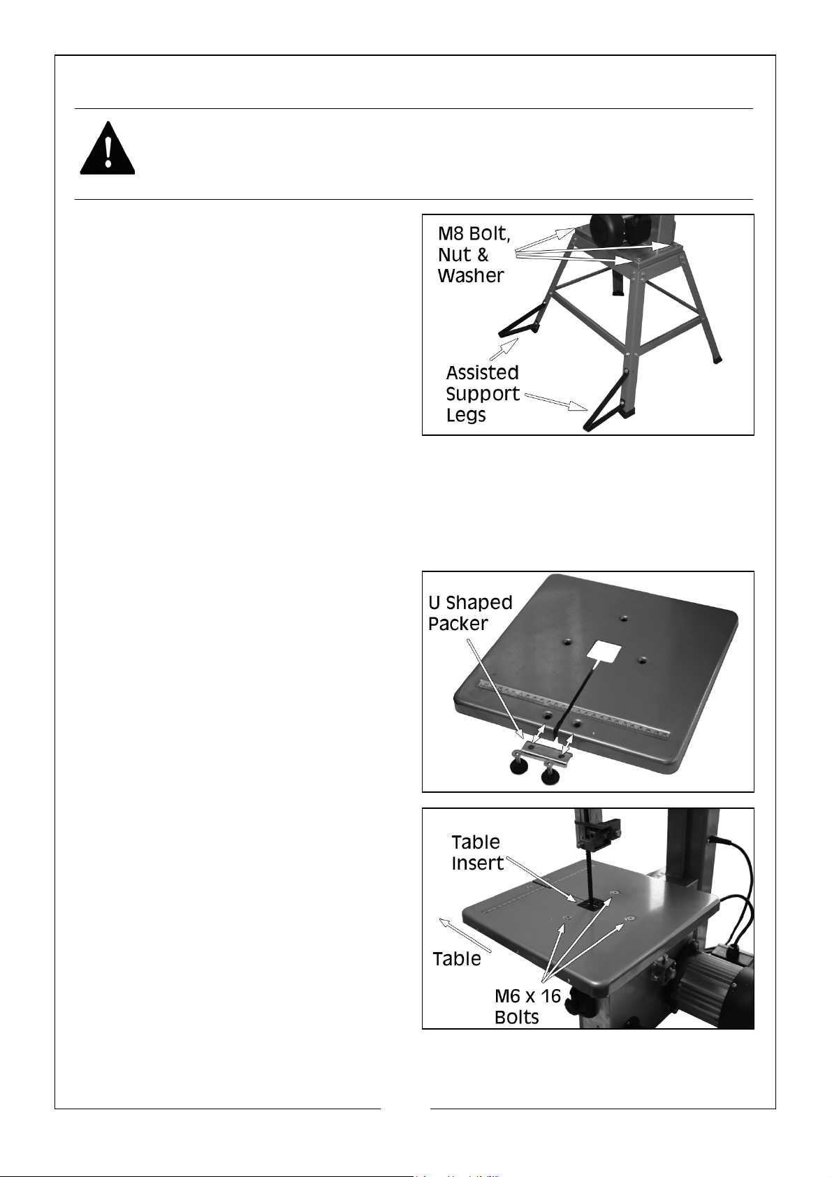
MOUNT THE BANDSAW ON TO THE STAND
WARNING: WHEN YOU MOUNT THE BAND SAW ON TO THE STAND WE
RECOMMEND THAT YOU GET HELP BECAUSE OF THE WEIGHT OF THE
BANDSAW.
1. Lift the bandsaw on to the stand,
making sure the motor is on the
same side as the assisted support
legs.
2. Use the 4 x M8 x 45 bolts, washers
and nuts supplied to attach the
band saw to the stand.
• Put the bolts through the base
of the saw from above.
• Install the washers and nuts on
the underside of the stand and tighten to secure.
3. Tighten all bolts and nuts on the saw and stand.
INSTALL THE SAW TABLE
1. Remove the two screws, knurled
nuts and U shaped packer from
the work table.
2. Guide the work table past the
blade and place on the table
trunnion. Position the table insert
on the work table correctly.
11
Parts & Service: 020 8988 7400 / E-mail: [email protected] or [email protected]
Page 12
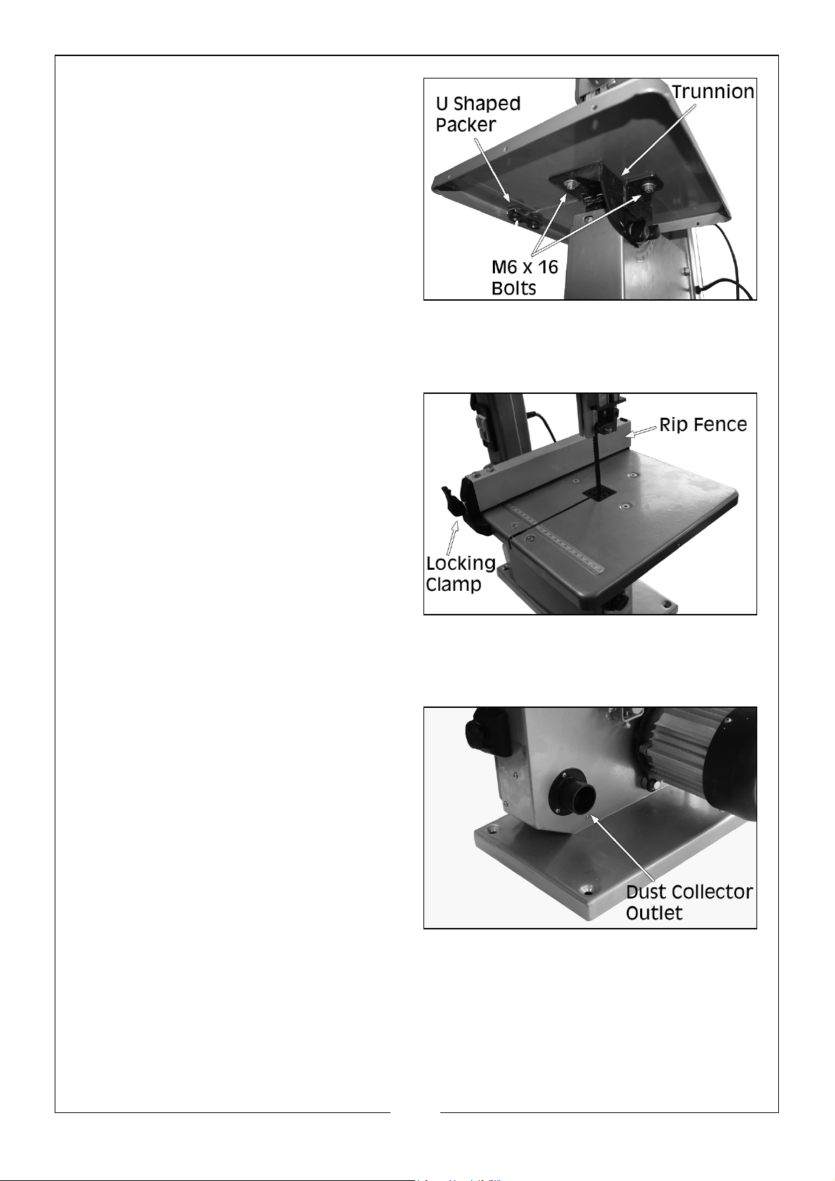
3. Attach the work table with 3 x M6
x 16 bolts, washers and nuts.
4. Attach the two screws, knurled
nuts and U shaped packer that
were removed in step one and
fasten
• ALWAYS replace the table insert
when worn.
FIT THE RIP FENCE TO THE TABLE
1. Loosen the locking clamp.
2. Slide the rip fence onto the table.
3. Tighten the locking clamp to
secure the rip fence in place.
CONNECTING TO A DUST COLLECTOR
This bandsaw is fitted with a dust port
to enable connection to a dust
collector.
• Outside Diameter 40 mm
• Inside Diameter 35 mm
The bandsaw is now ready to use.
12
Parts & Service: 020 8988 7400 / E-mail: [email protected] or [email protected]
Page 13
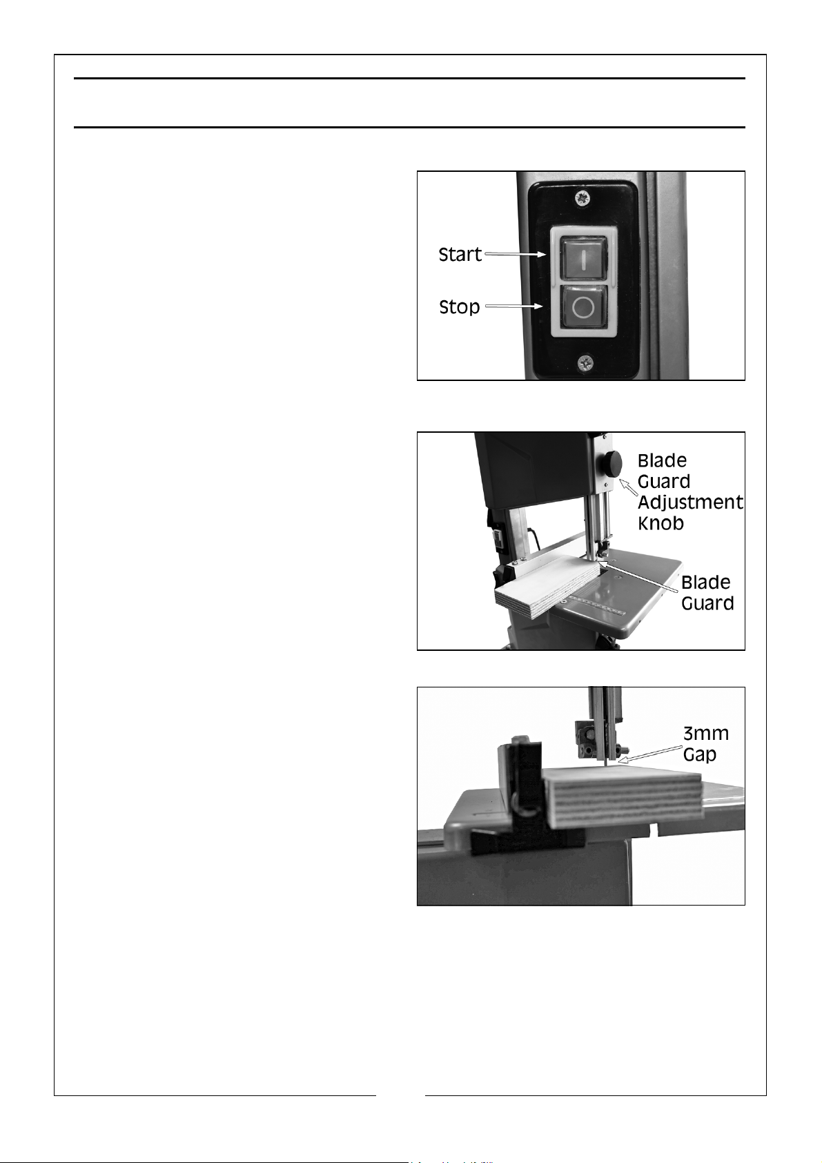
FUNCTIONS
SWITCHING ON/OFF
1. Press the green ON/START (I)
button to start the bandsaw.
2. Press the red OFF/STOP (O) button
to stop the bandsaw.
NOTE: The blade may continue to
rotate for a short time before
coming to a complete stop.
UPPER BLADE GUARD ADJUSTMENT
1. Rotate the blade guard
adjustment knob:
• Clockwise to raise the blade
guard
• Anti-clockwise to lower the
blade guard.
NOTE: The blade guard should be
positioned approx. 3mm
above the workpiece the
blade is cutting.
13
Parts & Service: 020 8988 7400 / E-mail: [email protected] or [email protected]
Page 14
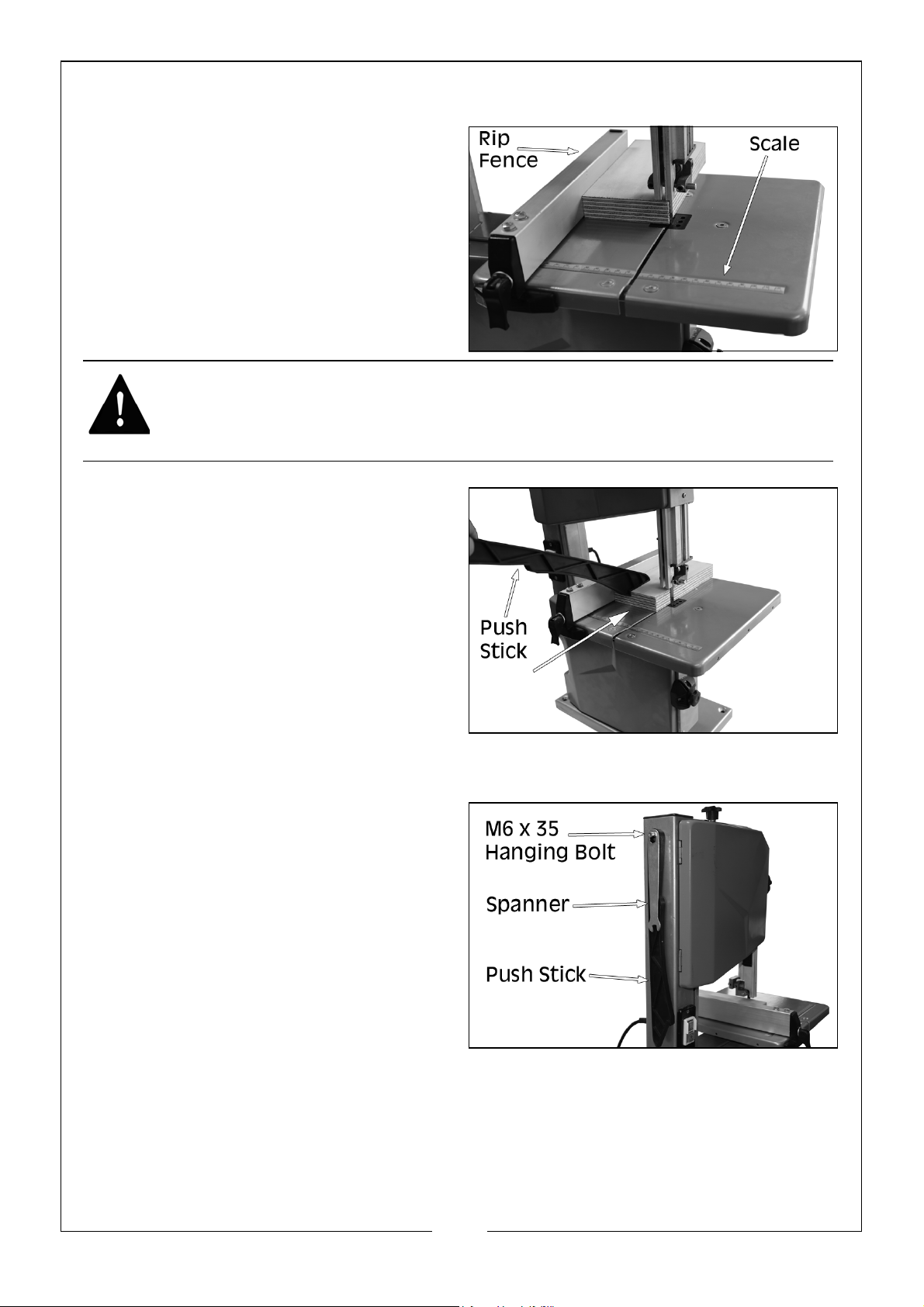
USING THE FENCE
• The rip fence can be used on
either side of the blade.The
scale indicates the distance
from the saw blade to the
fence.
1. Place the fence over the table
and into the required position and
press down the locking clamp to
hold the fence in position.
Warning: ALWAYS USE A PUSH STICK WHEN STRAIGHT CUTTING SMALL
WORK PIECES USING THE FENCE.
USING THE PUSH STICK
1. The push stick serves as an
extension of the operators hand
as protection against accidentally
touching the saw blade.
2. The push stick should be used if
the distance between the blade
and rip fence is less than approx.
150mm.
3. Always replace the push stick if
lost or damaged.
4. To reduce the chance of loss
always store the push stick on the
hanging bolt on the side of the
saw (M6 x 35 bolt & locking nut).
14
Parts & Service: 020 8988 7400 / E-mail: [email protected] or [email protected]
Page 15
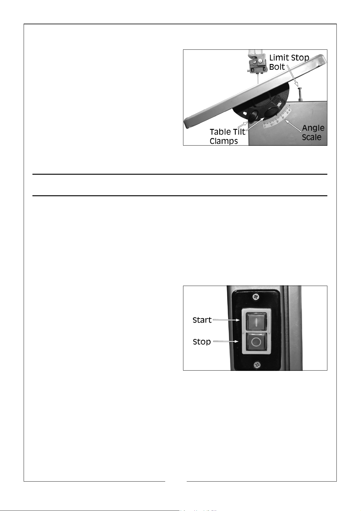
TILTING THE TABLE
1. Loosen the table tilt clamps.
2. Adjust the table to the required
angle.
• We recommend that you use
an engineers square to ensure
precise accuracy.
3. Retighten the table tilt clamps.
4. When table is level, adjust the limit
stop bolt so table rests on top of
the bolt.
OPERATION
Before commencing work, ensure the work area is clean and tidy and the
bandsaw table is clear of tools etc. Plan your work carefully and set the
bandsaw up accordingly before switching on.
1. Check the blade is correctly tensioned before use (see page 18).
2. Set the upper blade guide as close as practical to the workpiece, no more
than 3mm (see page 13). This provides the best safety for the operator and
gives more accurate results and greater control.
3. Switch on and allow the saw
blade to reach full speed before
proceeding.
• Use both hands to feed the
workpiece. The work must be
held flat on the table at all
times to prevent the blade from
binding
• Use a steady, even pressure,
just sufficient to keep the blade cutting.
• Always use the rip fence where possible to eliminate any sideways
movement of the work. This is most important when the table is tilted at
an angle.
• Remember that the blade removes material during the cut creating a
gap called the ‘kerf’, which must be allowed for when cutting to exact
sizes. Plan your cut so that the kerf is the scrap side of the line you wish to
cut. Where necessary, allow a little more material for finishing.
15
Parts & Service: 020 8988 7400 / E-mail: [email protected] or [email protected]
Page 16
• Always use a suitable holding device when cutting round or irregular
shaped timber to prevent twisting of the work piece.
CHANGING THE SAW BLADE
WARNING: DISCONNECT THE SAW FROM THE MAINS SUPPLY BEFORE
CHANGING THE BLADE.
REMOVING THE BLADE
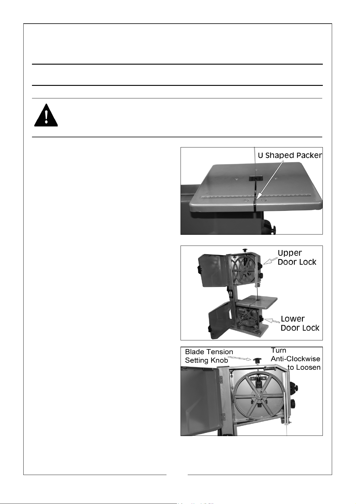
1. Loosen the 2 knurled screws and
remove the U shaped packer.
2. Open the upper and lower doors.
Turn the door locks clockwise to
unlock.
3. Loosen the setting knob anticlockwise until the bandsaw
blade has slackened.
4. Remove the old blade and
replace with a new blade (see
page 17).
16
Parts & Service: 020 8988 7400 / E-mail: [email protected] or [email protected]
Page 17
FITTING A BLADE
WARNING: BLADES ARE NORMALLY SUPPLIED COILED, TAKE CARE WHEN
UNCOILING THE SAW BLADE AS THEY HAVE A TENDENCY TO SPRING
OPEN. WE HIGHLY RECOMMEND THAT CUT PROOF GLOVES ARE WORE
WHEN FITTING A BLADE.
1. Slide the new blade over the wheels, making sure the teeth point towards
the front of the saw.
NOTE: Turning the wheels as you do so makes this easier.
• Centre the blade on the rubber tyres of the wheels.
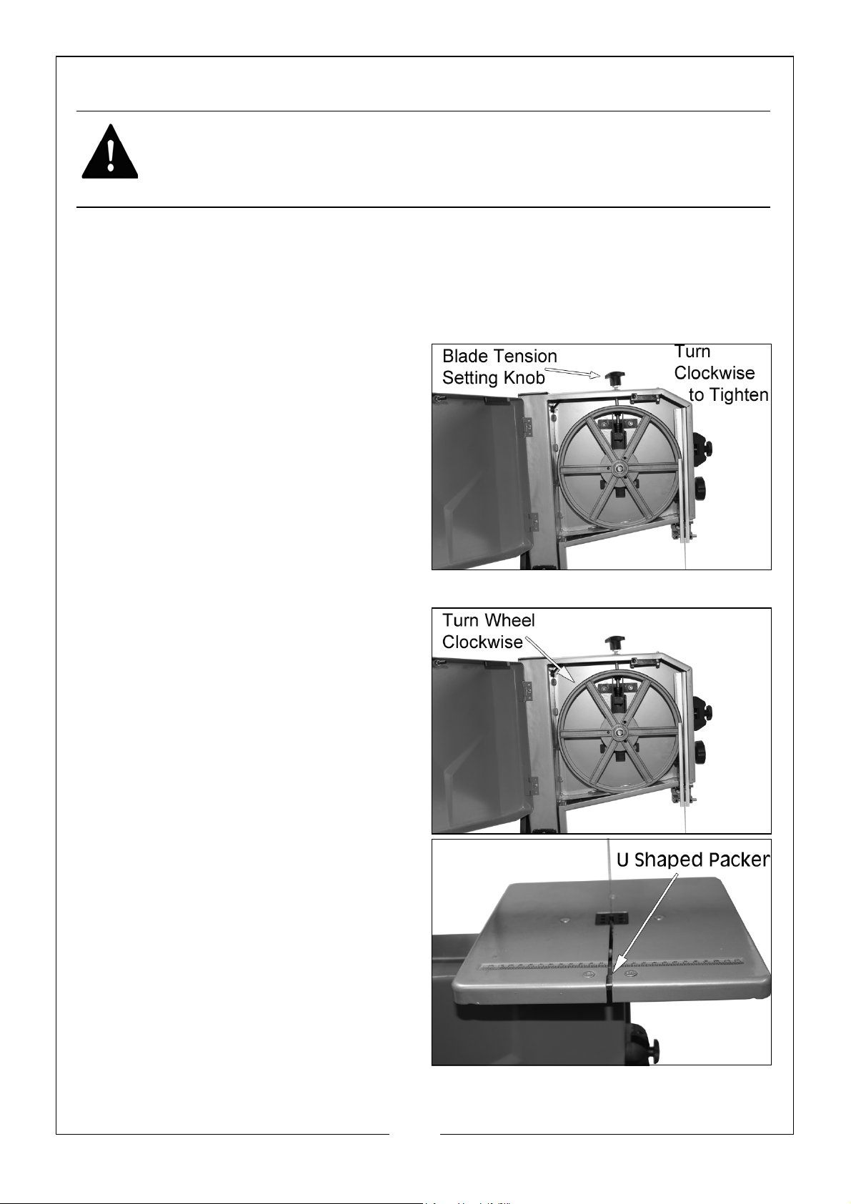
2. Tighten the blade tension setting
knob clockwise until the blade no
longer slips off the bandsaw
wheels.
3. Turn the upper wheel clockwise
by hand to make sure that the
blade tracks correctly on the
wheels.
• If not see “Tracking the Saw
Blade” on page 18.
4. Close and secure the doors.
5. Replace the U shaped packer.
6. Tension bandsaw blade; Align the
bandsaw blade and align the
blade guides. Run the saw for at
least one minute, stop the saw,
unplug and recheck the settings
and tension (see page 18).
17
Parts & Service: 020 8988 7400 / E-mail: [email protected] or [email protected]
Page 18
ADJUSTING THE BLADE TENSION
CAUTION: TOO MUCH TENSION CAN CAUSE THE BLADE TO BREAK. TOO
LITTLE TENSION CAN CAUSE THE BLADE TO MAKE IRREGULAR CUTS.
NOTE: Ensure the saw is turned
off and unplugged
before commencing.
1. Adjust the saw blade so it sits
dead centre on the rubber
tyres of the bandsaw wheels.
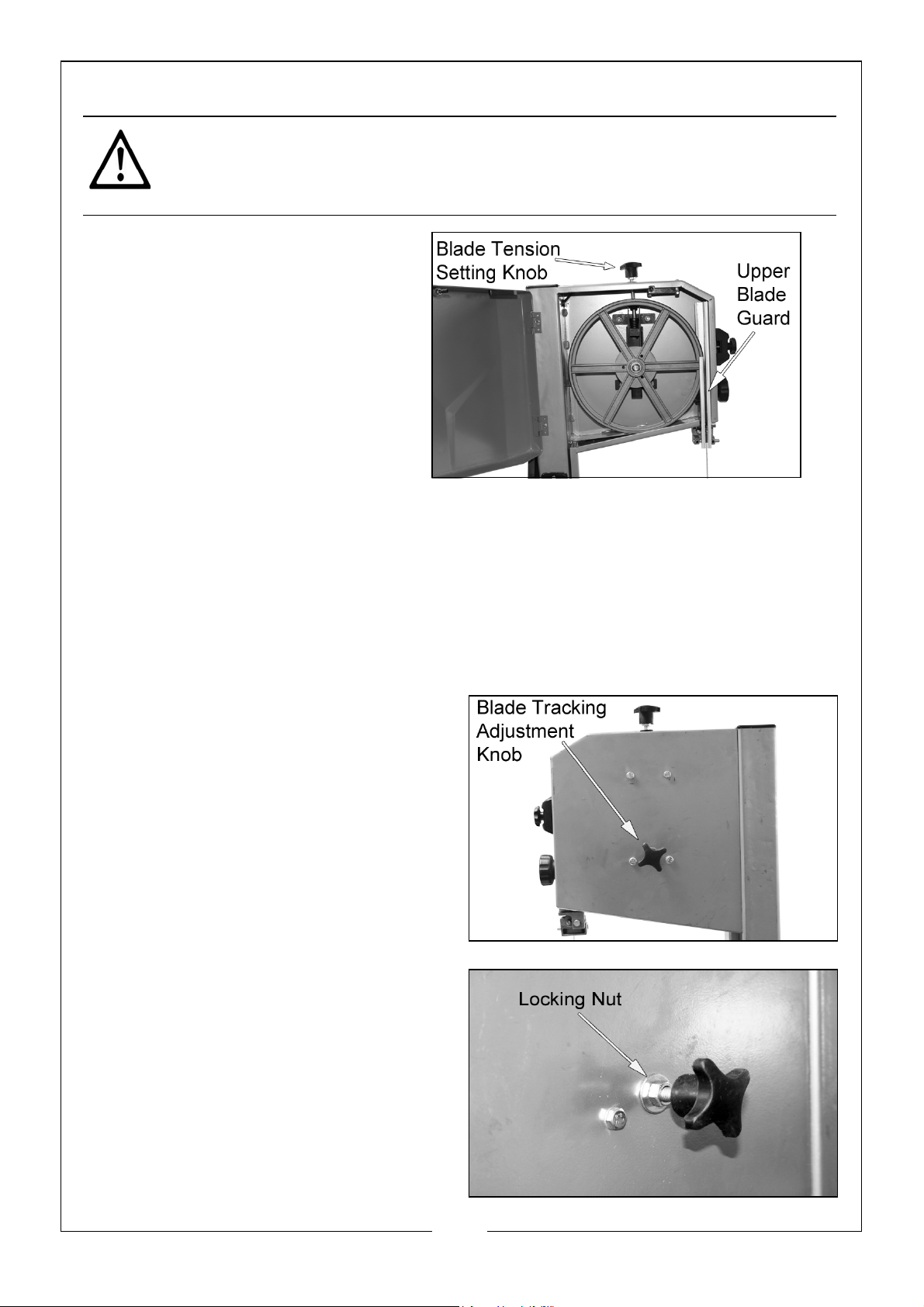
2. Raise the upper blade guard
fully (see page 13).
3. Turn the blade tension setting
knob to required tension.
• Turning the setting knob clockwise increases the blade tension.
• Turning the setting knob counter clockwise reduces the blade tension.
4. Check the tension by pressing with a finger against the side of the blade,
halfway between the table and upper guard.
• The blade should not flex more than 2 mm.
TRACKING THE SAW BLADE
If the saw blade does not run on the
centre of the rubber tyre, the
tracking needs to be corrected by
adjusting the tilt of the upper
bandsaw wheel.
1. Loosen locking nut
2. Turn blade tracking adjustment
knob:
• Turn clockwise if the saw blade
runs towards the front of the
saw
18
Parts & Service: 020 8988 7400 / E-mail: [email protected] or [email protected]
Page 19
• Turn anti-clockwise if the saw blade runs towards the rear of the saw.
3. Tighten locking nut.
ADJUST THE GUIDE/THRUST BEARINGS AND LOWER BLADE GUIDES
The guide/thrust bearings and the lower blade guides help keep the blade
tracking straight and correctly aligned during use.
UPPER BLADE GUIDE ALIGNMENT
NOTE: The bearing and guide pins need to be readjusted after every
bandsaw blade change or tracking.
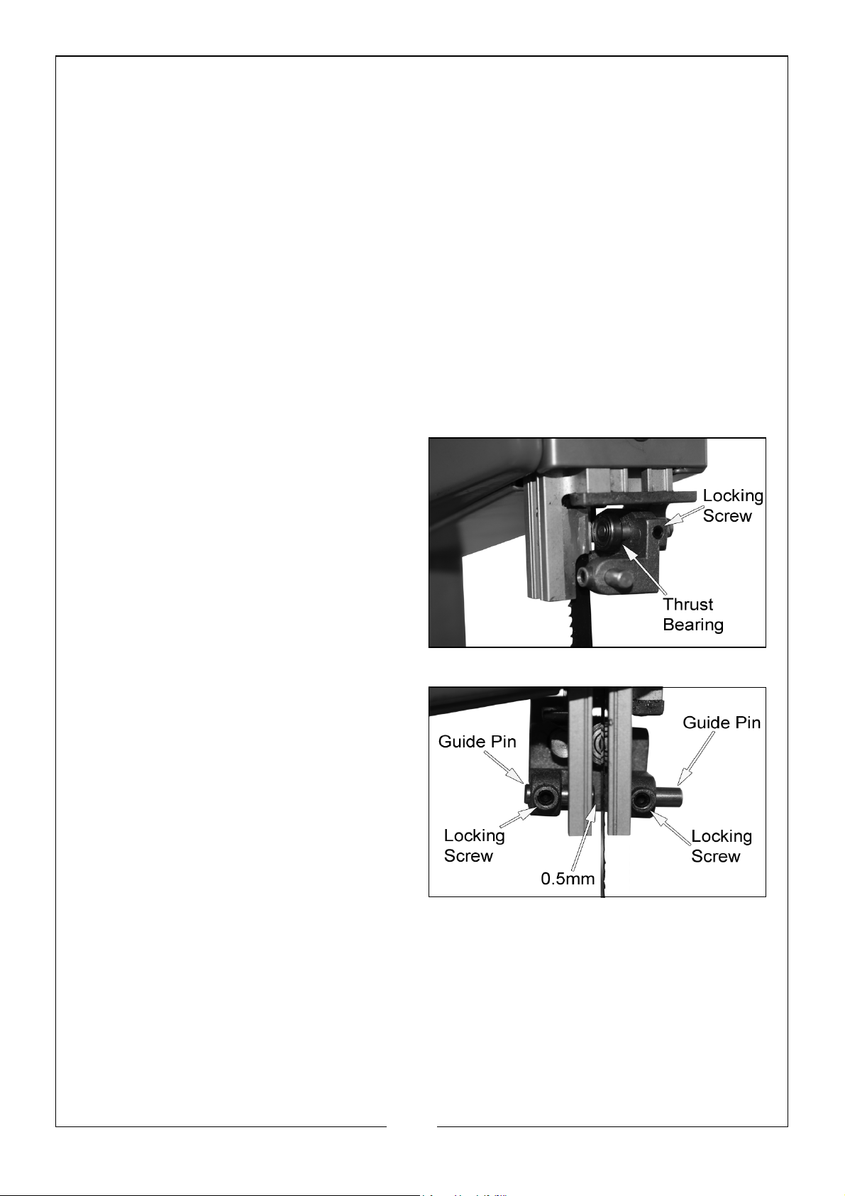
The upper blade guide consists of:
• A thrust bearing (supports the bandsaw blade from the rear)
• Two guide pins (providing lateral support)
UPPER THRUST BEARING ADJUSTMENT
1. If necessary, adjust the blade
tension and tracking. (see page
18)
2. Using the 3mm allen key, loosen
the locking screw and adjust the
bearing so that it is approximately
0.5mm from the blade.
3. Retighten the locking screw.
UPPER GUIDE PIN ADJUSTMENT
1. Using the 3mm allen key, loosen
the locking screws.
2. Press the guide pins together,
keeping 0.5mm distance
between guide pin and saw
blade.
3. Retighten the locking screws.
LOWER BLADE GUIDE ALIGNMENT
NOTE: The bearing and guide pins need to be readjusted after every
bandsaw blade change or tracking.
The lower blade guide consists of:
• A thrust bearing (supports the bandsaw blade from the rear)
• Two guide pins (providing lateral support)
19
Parts & Service: 020 8988 7400 / E-mail: [email protected] or [email protected]
Page 20
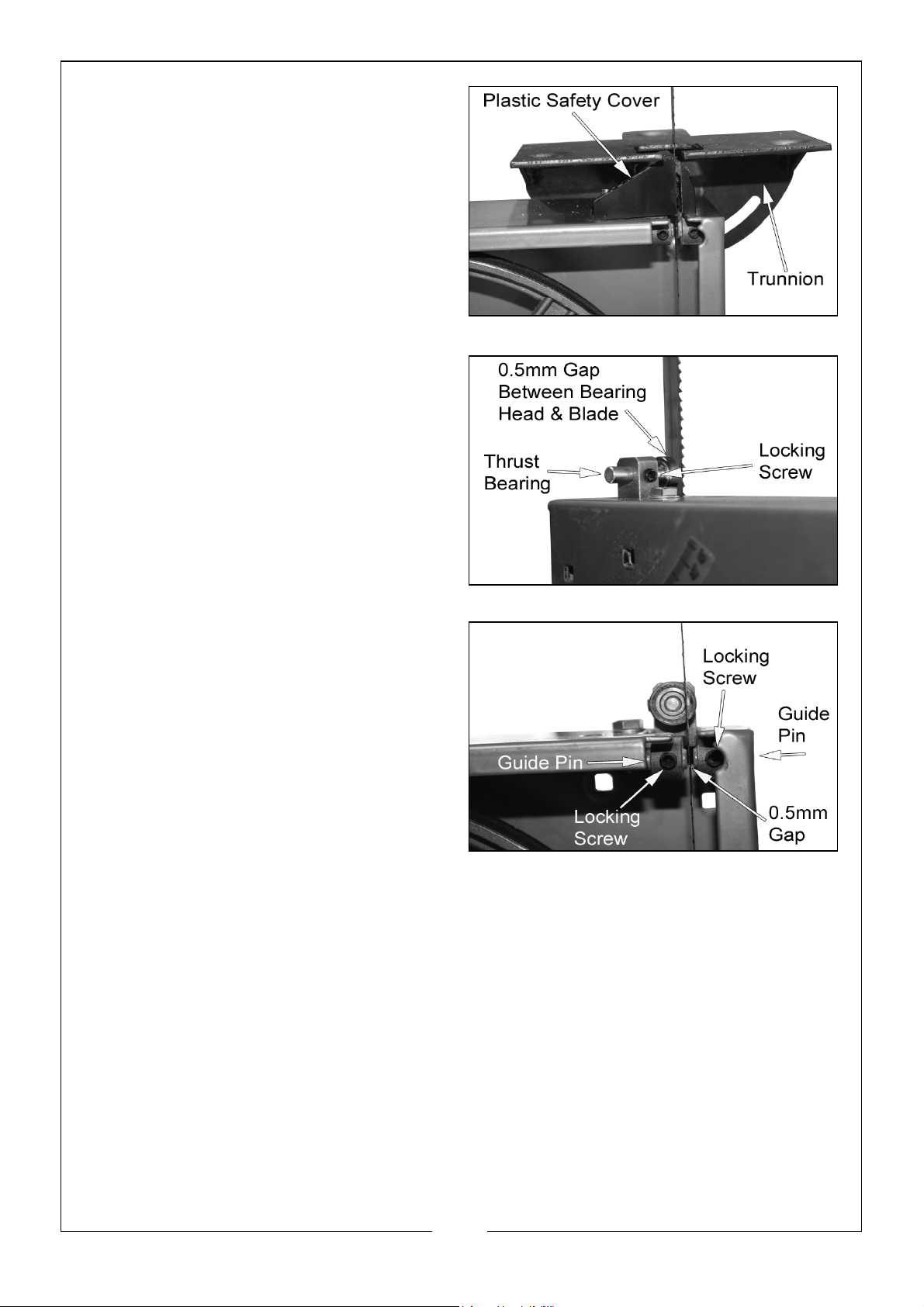
LOWER THRUST BEARING ADJUSTMENT
1. Open the lower door.
2. Remove the table, trunnion and
plastic safety cover from the saw.
3. Raise the upper blade guide fully.
4. If necessary, align and tighten the
bandsaw blade (page 18)
5.
6. Using the 3mm allen key, loosen
the locking screw and adjust the
bearing so that it is approximately
0.5mm from the blade.
7. Retighten the locking screw.
LOWER GUIDE PIN ADJUSTMENT
1. Using the 3mm allen key, loosen
the locking screws
2. Press the guide pins together,
keeping 0.5mm distance
between guide pin and saw
blade
3. Retighten the locking screws.
20
Parts & Service: 020 8988 7400 / E-mail: [email protected] or [email protected]
Page 21
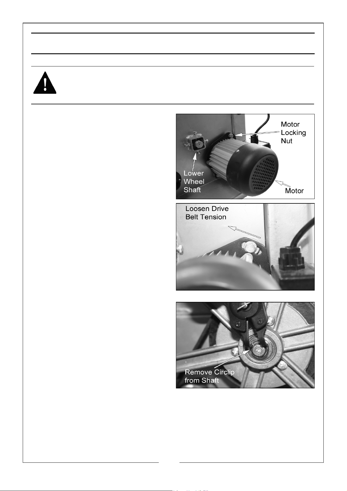
DRIVE BELT
WARNING: DISCONNECT THE SAW FROM THE MAINS SUPPLY BEFORE
CHANGING THE BELT.
DRIVE BELT CHANGE
To change the drive belt, you will
need a pair of circlip pliers
1. Follow the steps for removing the
saw blade as described on page
16.
2. Loosen, using a size 14 spanner,
only the upper motor locking nut
that is holding the motor in place.
Twist the motor to the left to
loosen the belt.
3. Using circlip pliers, remove the
circlip that holds the lower wheel
on the shaft. Slide the lower saw
wheel and big pulley off the shaft.
this will dislodge the drive belt.
21
Parts & Service: 020 8988 7400 / E-mail: [email protected] or [email protected]
Page 22
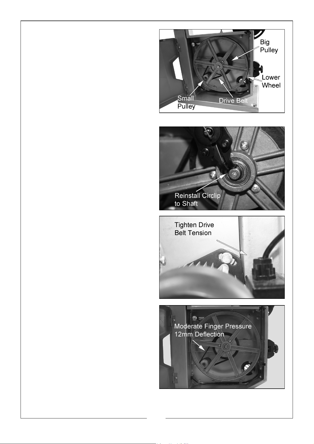
4. Place the new drive belt round
the big pulley wheel and stretch
over the small pulley wheel.
5. Reinstall the lower saw wheel with
big pulley by sliding it back onto
the shaft, then secure with the
shaft circlip.
6. Place the new belt partially
around the big pulley to get it
started, then turn the wheel by
hand until the belt is completely
seated on the big pulley.
7. Twist the motor to the right to add
tension to the belt. The belt is
properly tensioned when
moderate finger pressure on the
belt between the pulleys causes a
12mm deflection.
8. Tighten the locking bolt on the
back of the cabinet that secures
the motor.
9. Re-install the blade as described
on page 17.
22
Parts & Service: 020 8988 7400 / E-mail: [email protected] or [email protected]
Page 23
MAINTENANCE AND SERVICING
DAILY/AFTER USE
1. Keep the machine clean using a vacuum cleaner and wipe down with a
damp cloth.
2. Check the saw blade for missing teeth and cracks.
3. Open the top & bottom wheel covers and clean out all saw dust with a
vacuum cleaner.
MONTHLY
1. Open the lower and upper door and check the condition of the wheels,
tyres and blade.
• If required clean the tyres.
2. Using an air line (wearing goggles) blow out the motor casing.
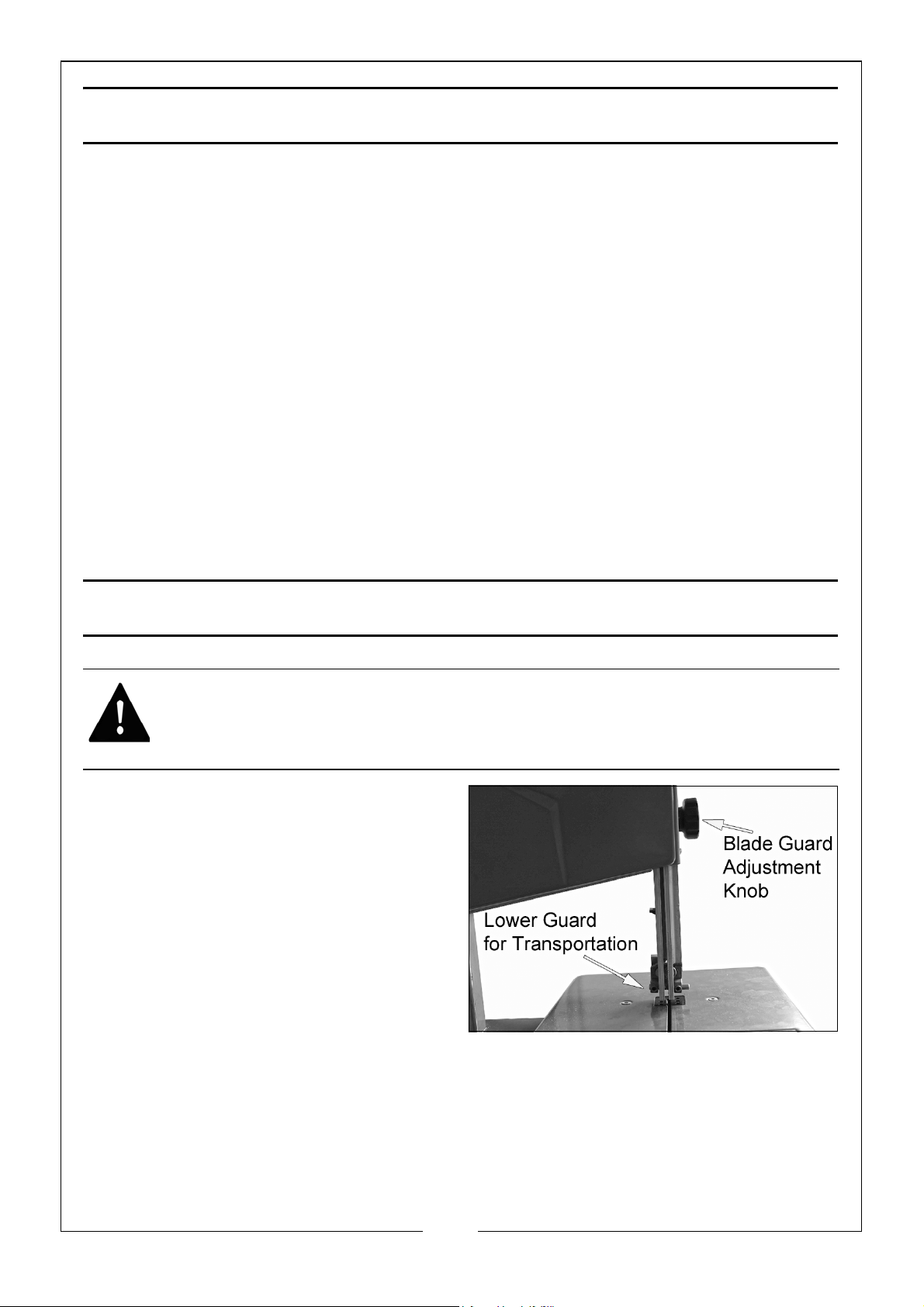
TRANSPORTING THE BANDSAW
WARNING: DO NOT USE GUARDS FOR HANDLING OR TRANSPORTATION
• Always transport the tool with
the blade guard in the fully
lowered position so the blade is
fully covered.
• Ensure both upper and lower
doors are locked closed.
• Due to the weight and height
when the saw is fixed to the
stand, it is recommended that
you detach the saw from the
stand when moving the machine.
23
Parts & Service: 020 8988 7400 / E-mail: [email protected] or [email protected]
Page 24
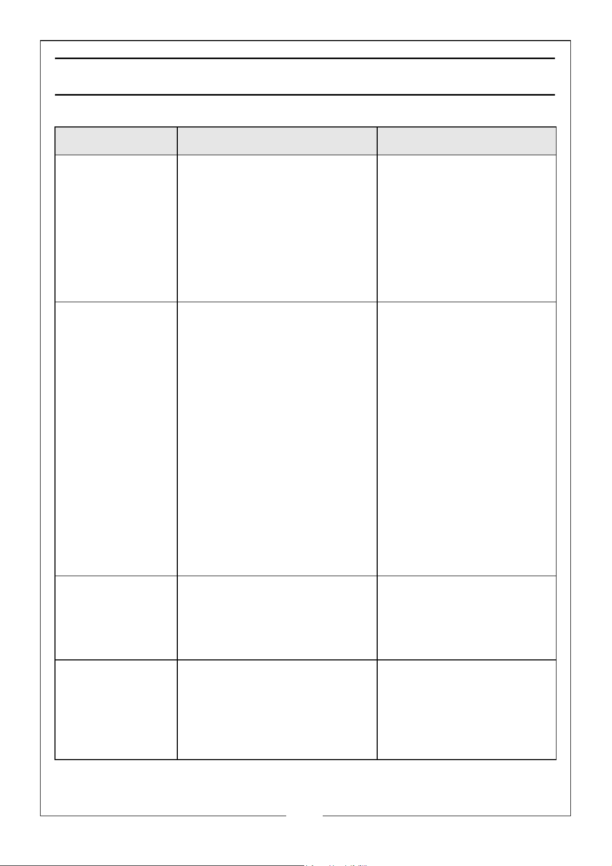
TROUBLESHOOTING
FAULT CHECK SOLUTION
The unit fails to
operate
Blade breaks 1. Faulty alignment (tracking)
1. Check for power failure if
the unit is plugged in.
2. Check the switch is on and
that the fuse is not blown.
3. Upper or lower door
safety switch disengaged.
2. Blade guides incorrectly
adjusted.
3. Feeding the work too fast.
4. Forcing or twisting the blade
around a tight radius.
5. Blade too tight.
6. Blunt teeth.
7. Blade is badly welded or
brazed.
8. Wrong blade fitted.
1. Plug the unit into the
socket.
2. Replace fuse or switch
on.
3. Check that upper/lower
doors are fully closed
4. Make sure the safety
switches are seated
correctly
1. Carry out tracking
adjustments (p18).
2. Re-adjust blade guides
(p19-20)
3. Lower the feed rate
4. For tight curves, make
relief cuts fairly close
together at 90º to the
curve. A narrower blade
will make a tighter
curve.
5. Relieve blade tension
6. Renew blade
7. Renew blade
8. Fit only quality blades
supplied by your CLARKE
dealer.
Noise or vibration 1. Blade not correctly aligned.
2. Guides not accurately set.
Blade runs off the
cutting line
Parts & Service: 020 8988 7400 / E-mail: [email protected] or [email protected]
1. Blade guides incorrectly
adjusted.
2. Blade tracking mal-adjusted
3. Blade tension too slack.
4. Wrong blade fitted (too
thin).
24
1. Carry out tracking
adjustments (p18).
2. Tighten the locking
knob. Check guides are
correctly set (p19-20).
1. Re-adjust blade guides
(P19-20).
2. Carry out tracking.
adjustment (p18).
3. Re-tension blade.
4. Fit correct blade.
Page 25
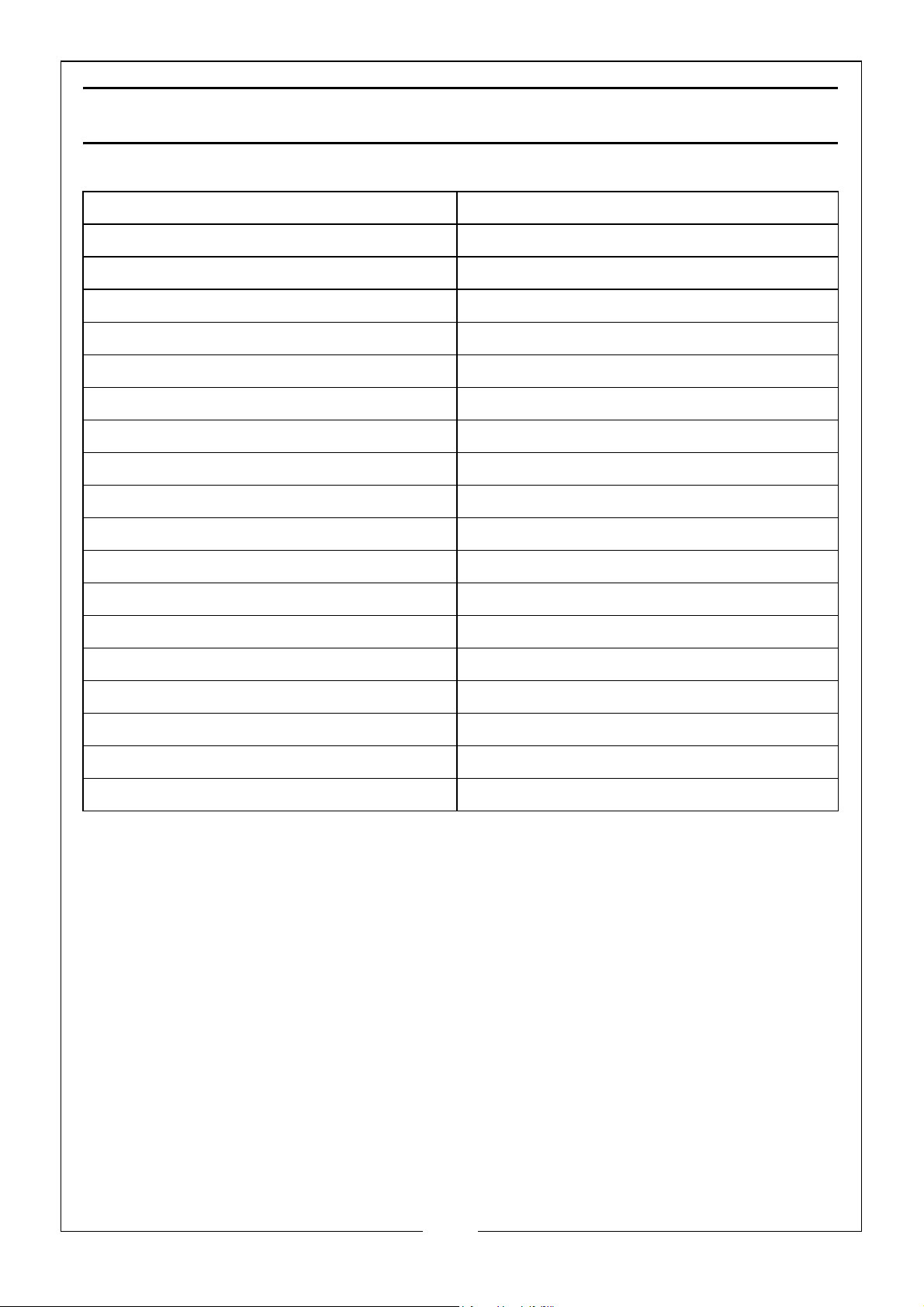
SPECIFICATIONS
Model CBS250C
Power 500W, 230V/50Hz, 5A
Blade T10 Carbon Tool Steel, 6 p.t.i
Blade Speed 467 rpm
Blade Length 1,712 mm
Blade Width 8-10 mm
Max Width of Cut (Throat Width) 245 mm
Max Depth of Cut 115 mm @ 90° / 65 mm @ 45°
Table Size 302 x 304 mm
Table Height on Stand 884 mm
Table Tilt Angle 90° to 45°
Dust Extraction Outlet 35 mm (inside) / 40 mm (outside)
IP Rating IP20
Duty Cycle Classification S1 (Continuous)
Sound Pressure Level 82.3 dB LpA
Sound Power Level 94.4 dB LWA
Sound Uncertainty Factor (K) 3 dB
Dimensions (L x W x H) 730mm x 550mm x 1310mm
We ig ht (B an ds aw an d St an d) 2 9. 6 k g
25
Parts & Service: 020 8988 7400 / E-mail: [email protected] or [email protected]
Page 26
Page 27
Page 28
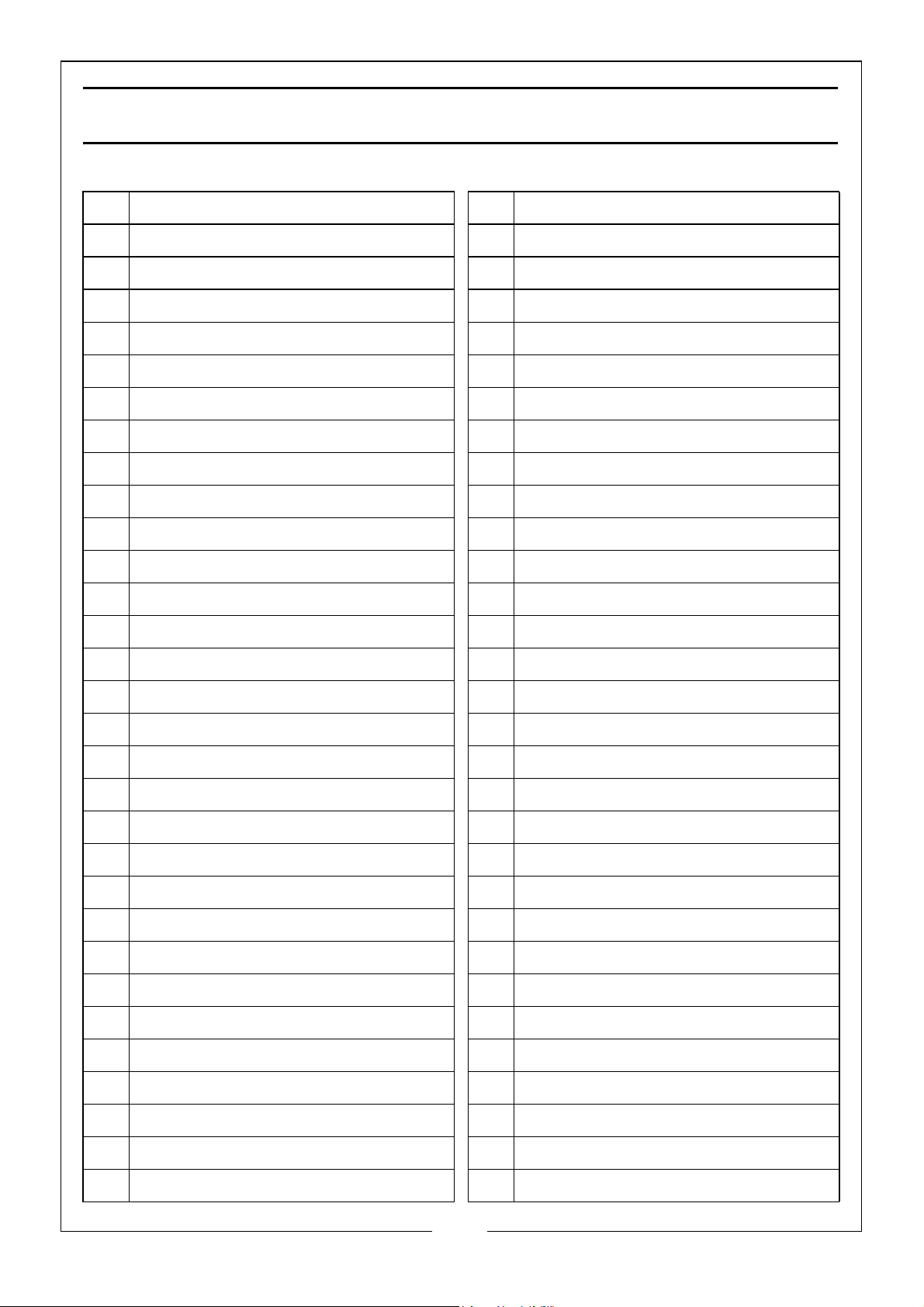
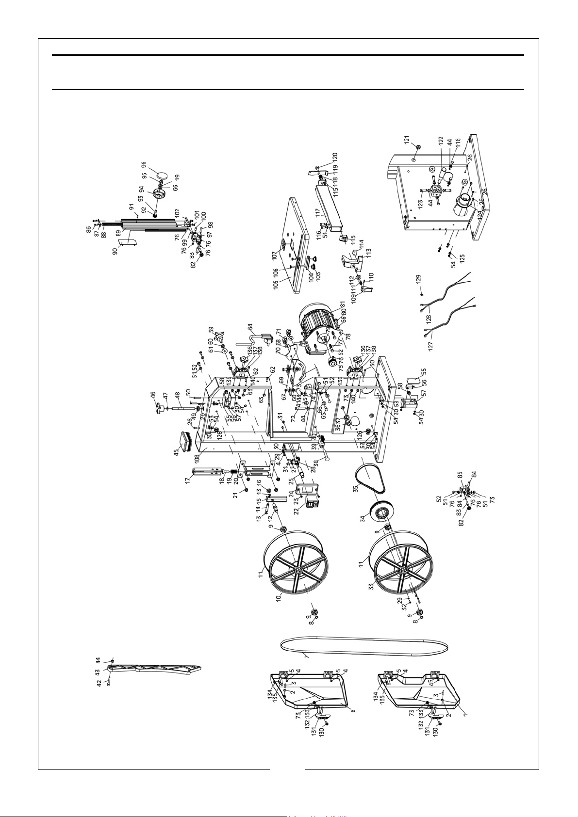
PARTS LIST
001 Lower Housing Door 032 Screw M4 x 16
002 Nut M5 033 Bandsaw Wheel - Lower
003 Screw M5 x 25 034 Pulley - Lower
004 Screw M4 x 8 035 Belt
005 Flat Washer 4 036 Nut M14 x 1.5
006 Upper Housing Door 037 Spring Washer 14
007 Saw Blade 038 Bolt M8 x 70
008 Shaft Circlip 10 039 Brush
009 Bearing 6000-2Z 040 Bushing
010 Bandsaw Wheel - Upper 041 Nut M8
011 Rubber Tyre 042 Screw M6 x 35
012 Upper Pulley Shaft 043 Push Stick
013 Shaft Circlip 8 044 Nut M6
014 Horizontal Shaft 045 Column Plug
015 Upper Wheel Shaft Seat 046 Nut M8
016 Thin Nut M10 047 Thin Nut M8
017 U Shaped Bracket 048 Adjusting Rod
018 Central Spindle 049 Supporting Bushing
019 Wing Spring 050 Screw M4 x 25
020 Guide Plate Assembly 051 Flat Washer 6
021 Nut M6 052 Bolt M6 x 16
022 On/Off Switch 053 Cable Clip
023 Screw M4 x 12 054 Nut M4
024 Switch Plate 055 Microswitch Box Cover
025 Cable Sheath 056 Microswitch
026 Screw M4 x 10 057 Microswitch Box
027 Cable Pressing Plate 058 Power Cable Buckle
028 Cable Fixing Plate 059 Knob Bolt M8 x 25
029 Spring Washer 4 060 Nut M8
030 Lock Washer 4 061 Big Flat Washer 8
031 Screw M5 x 10 062 Screw ST4.2 x 13
28
Parts & Service: 020 8988 7400 / E-mail: [email protected] or [email protected]
Page 29
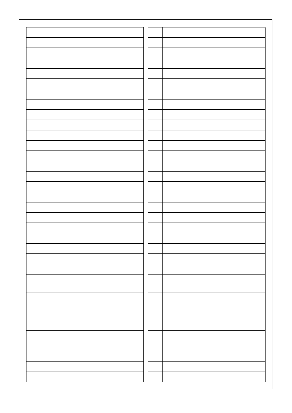
063 Guide Block 096 Adjusting Knob Cover
064 Plug & Power Cable 097 Upper Blade Guide
065 Bolt M6 x 20 098 Upper Guide Pin
066 Flat Washer 8 099 Fixing Rod
067 Bolt M6 x 16 100 Screw M6 x 12
068 Big Flat Washer 6 101 Screw ST4.2 x 13
069 Bench Angle Gauge 102 Upper Blade Guide Seat
070 Lock Plate 103 Locknut
071 Lock Knob 104 U Shaped Packer
072 Bolt M6 x 35 105 Work Table
073 Locknut M6 106 Bolt M6 x 20
074 Blade Guide 107 Table Insert
075 Motor Pulley 108 Machine Body Weldment
076 Screw M6 x 6 109 Rip Fence Locker
077 Spring Washer 6 110 Pin 3 x 16
078 Motor Connecting Plate 111 Connecting Bushing
079 Flat Key 5 x 25 112 Flat Washer 10
080 Bolt M8 x 20 113 Rip Fence Holder
081 Motor 114 Stop Block
082 Bearing 625-2Z 115 Clamping Block
083 Bearing Shaft 116 Bolt M6 x 10
084 Lower Guide Pin 117 Rip Fence
085 Lower Blade Guide 118 Rip Fence Spring
086 Screw ST3.5 x 9.5 119 Clamping Press Plate
087 Top Coverplate for Upper Blade
120 Clamping Screw Rod
Guide
088 Rack 121 Cable Gland Strain Relief
Connector
089 Upper Blade Guide 122 Lower Pulley Shaft
090 Sliding Plate 123 Bolt M6 x 20
091 Pin 2.5 x 12 124 Suction Connector
092 Gear 125 Lock Washer 5
093 Gear Shaft 126 Hood
094 Adjusting Knob Seat 127 Upper Microswitch Cable
095 Locknut M8 128 Lower Microswitch Cable
29
Parts & Service: 020 8988 7400 / E-mail: [email protected] or [email protected]
Page 30
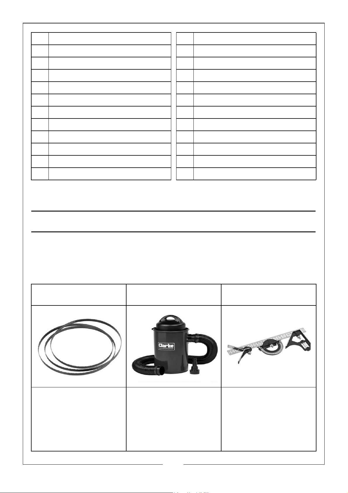
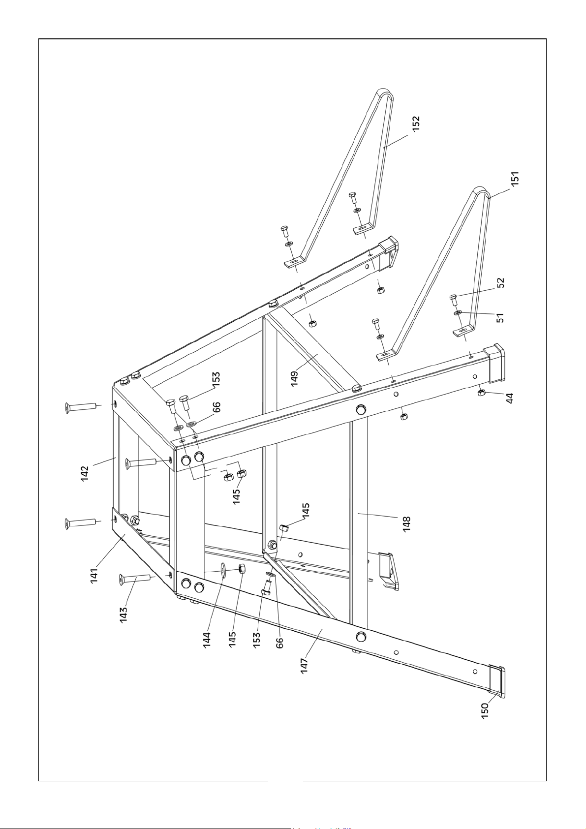
129 End Wire Connector 141 Long Beam
130 Screw M6 x 20 142 Short Beam
131 Inserter Seat 143 Bolt M8 x 45
132 Inserter 144 Big Flat Washer 8
133 Subplate 145 Nut M8
134 Self Plugging Rivet 4 x 8 147 Stand Leg
135 Leaf Spring 148 Short Support Plate
136 Knob Bolt M6 x 32 149 Long Support Plate
137 Fixing Seat for Door Lock 150 Rubber Foot
138 Screw M5 x 16 151 Assisted Support Leg - Left
139 Inserter 152 Assisted Support Leg - Right
140 Locknut M5 153 Bolt M8 x 16
SPARES & RELATED PRODUCTS
Replacement blades are available from your CLARKE dealer. Please quote
the following part number
6 TPI Bandsaw Blade Vacuum Dust Extractor
CWVE1
•1712mm Blade Length
•10mm Width
•Part No. 6460059
•Tank Capacity: 50
Litres
•Air Flow: 183m3/hr
(3.05m3/min)
•Part No. 6471168
Combination Try Square
CHT625
•Built-in Vertical &
Horizontal Spirit Levels
& Scribe
•Metric & Imperial
Markings
•Part No. 1801625
30
Parts & Service: 020 8988 7400 / E-mail: [email protected] or [email protected]
Page 31
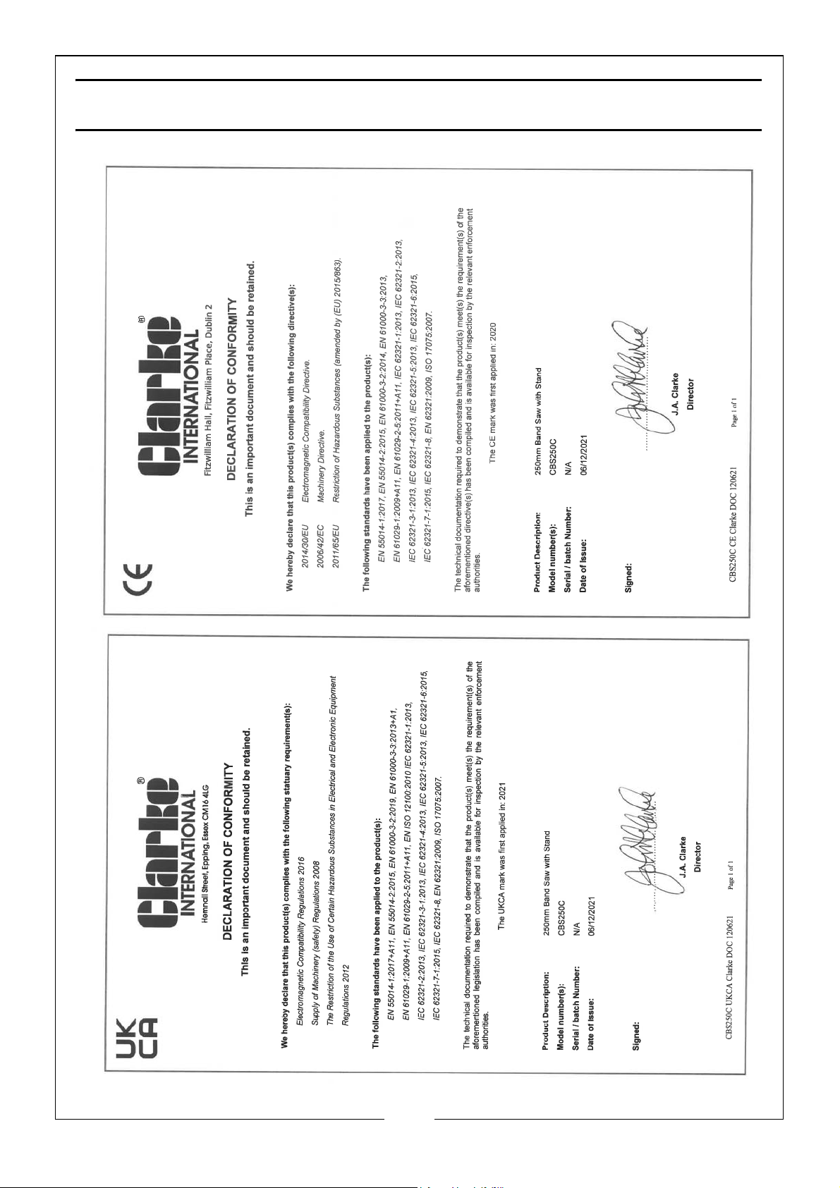
DECLARATION OF CONFORMITY
31
Parts & Service: 020 8988 7400 / E-mail: [email protected] or [email protected]
Page 32

 Loading...