

Page 1
190mm (7½”) BANDSAW
190mm (7½”) BANDSAW
Model: CBS 190
OPERATING & MAINTENANCE
INSTRUCTIONS
LS12/13
Page 2

SPECIFICATIONS
Motor .....................................................................................230VAC 50Hz 1Ph
Power Rating..............................................................350W
Capacitor...................................................................6 uF 450V
Current Rating............................................................3.5 Amps
Blade Speed ..........................................................................14.7 M/s
Blade Length..........................................................................1425mm (6tpi)
Max. Cutting Thickness .........................................................80 mm
Max. Cutting Width ...............................................................190 mm
Table Size................................................................................305 x 305 mm
O
Table Tilt ..................................................................................45
Dimensions .............................................................................425x370x675 mm
Weight net/gross..................................................................17.5/20 kg
right
Part Number...........................................................................6460130
These specifications are correct at the time of going to print. Clarke International reserves the right to change specifications at any
time in the inerests of safety or design change.
PARTS and SERVICE
Please contact your nearest dealer, or
CLARKE International, on one of the following numbers.
PARTS & SERVICE TEL: 020 8988 7400
PARTS & SERVICE FAX: 020 8558 3622
or e-mail as follows:
PARTS: [email protected]
SERVICE: [email protected]
2
Page 3

Thank you for purchasing this CLARKE CBS190 - 7½” Bandsaw, specifically designed for hobby and
DIY use.
Before attempting to operate the machine, please read this instruction manual thoroughly, and
carefully follow all directions, paying particular attention to the safety instructions. By doing so you
will ensure the safety of both yourself and others around you, and you can also look forward to the
Bandsaw giving you long and trouble free service.
GUARANTEE
This CLARKE product is guaranteed against faulty manufacture for a period of 12 months from the
date of purchase. Please keep your receipt which will be required as proof of purchase. This guarantee
is invalid if the product is found to have been abused or tampered with in any way, or not used for
the purpose for which it was intended.
Faulty goods should be returned to their place of purchase, no product can be returned to us
without prior permission. This guarantee does not effect your statutory rights.
CONTENTS Page
General Safety Precautions ......................................................... 4
Additional Safety Precautions for Bandsaws ............................. 5
Electrical Installation ..................................................................... 5
Unpacking...................................................................................... 6
Illustration of Principle Parts .......................................................... 6
Assembly ...................................................................................... 7
Preparation for Use........................................................................ 7
Operation ...................................................................................... 8
Dust Extraction ............................................................................... 8
Tips on Bandsaw Use ..................................................................... 8
Ripsawing .................................................................... 9
Cross Cutting............................................................... 9
Freehand Sawing ....................................................... 9
Maintenance ............................................................................... 10
Blade renewal........................................................... 10
Blade Tracking .......................................................... 10
Blade Guide Adjustments........................................ 11
Troubleshooting ........................................................................... 13
Parts Lists & Diagrams.................................................................. 14
Specifications............................................................................... 15
Parts and Service contacts ........................................................ 15
3
Page 4

SAFETY PRECAUTIONS
and adjusting wrenches are removed from
the machine before switching on.
GENERAL SAFETY RULES FOR OPERATING
MACHINERY
WARNING:
As with all machinery, there are certain
hazards involved with their operation and use.
Exercising respect and caution will
considerably lessen the risk of personal injury.
However, if normal safety precautions are
overlooked, or ignored, personal injury to the
operator may result.
1. READ and BECOME FAMILIAR with the entire
operating manual. Learn the applications and
limitations of the machine as well as the
specific potential hazards peculiar to it.
2. ALWAYS ENSURE THAT ADEQUATE LIGHTING is
available. A minimum intensity of 300 lux
should be provided. Ensure that lighting is
placed so that you will not be working in your
own shadow.
3. CHECK for DAMAGE. Before use, any
damaged part, such as a guard etc., should
be checked to ensure that it will operate
properly, and perform its intended function.
Check for alignment of moving parts,
breakage of parts, mountings, and any other
condition that may effect the machines’
operation. Any damage should be properly
repaired or the part replaced. If in doubt, DO
NOT USE the machine. Consult your local
dealer.
4. DISCONNECT the MACHINE from the power
supply before servicing and when changing
accessories or blades etc.
5. KEEP GUARDS in place and in working order.
6. ALWAYS WEAR SUITABLE SAFETY GOGGLES
manufactured to the latest European Safety
Standards. Also use a face or dust mask if
cutting or sanding operation is dusty.
Everyday eyeglasses do not have impact
resistant lenses, they are NOT safety glasses.
7. KEEP WORK AREA CLEAN. Cluttered areas and
benches invite accidents.
8. ALWAYS wear Ear Protectors/Defenders
9. DON’T FORCE the Machine. It will do a better
and safer job at the rate for which it was
designed.
10. REMOVE ADJUSTING KEYS AND SPANNERS.
Form the habit of checking to see that keys
11. DRUGS, ALCOHOL, MEDICATION. Do not
operate machine while under the influence
of drugs, alcohol or any medication.
12. USE RECOMMENDED ACCESSORIES. The use
of improper accessories could be hazardous.
13. NEVER LEAVE MACHINE RUNNING
UNATTENDED. Turn power OFF. Do not leave
the machine until it comes to a complete
stop.
14. EARTH ALL MACHINES. If the machine is
equipped with three-pin plug, it should be
plugged into a three-pin electrical socket.
Never remove the earth pin.
15. A VOID DANGEROUS ENVIRONMENT . Don’t use
power machines in damp or wet locations or
expose them to rain. Keep your work area well
illuminated. DO NOT use in explosive
atmosphere (around paint, flammable liquids
etc).
16. KEEP CHILDREN AWAY. All visitors should be
kept a safe distance from the work area,
especially whilst operating the unit.
17. MAINT AIN MACHINE IN TOP CONDITION. Keep
tools sharp and clean for the best and safest
perfor mance. Follow maintenance
instructions.
18. DON’T OVERREACH. Keep your proper footing
and balance at all times. For best footing wear
rubber soled footwear . Keep floor clear of oil,
scrap wood, etc.
19. WEAR PROPER APPAREL. Loose clothing or
jewellery may get caught in moving parts.
Wear protective hair covering to contain
long hair.
20. MAKE WORKSHOP CHILDPROOF. Lock all
machines when not in use by removing the
safety keys if fitted, and store in a safe
location.
21. AL W A YS use in a well ventilated area. Remove
sawdust frequently, and clean sawdust out
from the interior of the machine to avoid
producing a potential fire hazard.
22. AVOID ACCIDENTAL STARTING. Ensure the
switch is OFF before plugging in to the mains.
23. BE AWARE that many accidents are caused
by carelessness due to familiarity. ALWAYS
concentrate on the job in hand, no matter
how trivial it may seem.
24. Never use the machine in the vicinity of
flammable or combustible liquids.
4
Page 5

ADDITIONAL SAFETY RULES FOR
ELECTRICAL INSTALLATION
BANDSAWS
• Set the blade guide block assembly as close
as possible to the workpiece.
• Switch off the saw, and make sure the blade
has come to a complete stop before clearing
sawdust or off-cuts from the table.
• Keep the saw properly adjusted, paying
particular attention to the blade tension and
tracking, and position of the blade guides.
• Disconnect the saw from the mains supply
before removing the wheel cover.
• Make sure there are no nails or foreign objects
in the part of the workpiece to be sawn.
• Be extra cautious with very large or small, or
irregularly shaped workpieces.
• Set up the machine and make all adjustments
with the power OFF.
• NEVER operate the machine with the wheel
cover or blade guards off. They must all be in
place and securely fastened when
performing any operation.
• When cutting large or oversize stock, always
ensure the material is supported at table
height.
• Any adjustable component must be securely
locked in position to ensure it cannot vibrate
free during operation.
• When sawing curves, make relief cuts to allow
removal of scrap material. This will prevent
undue twisting or binding of the saw blade.
Make the relief cuts before starting a curved
cut.
• When sawing, hold material firmly, and feed
into blade at a moderate speed.
• DO NOT saw any material that does not have
a flat surface on which to bear, unless a
suitable support is used. Round or tubular work
has a tendency to roll, and causes the blade
to ‘bite’....always use a suitable device to
hold round material securely.
• Ensure the bandsaw is securely fixed in
position before operating.
• When cutting with the table tilted...ensure the
parallel fence is mounted to the right of the
saw blade.
• Never cut workpieces that cannot be held
comfortably and securely by hand.
• ALWAYS wear Safety Goggles and Ear
Defenders. We also strongly recommend the
use of a breathing mask.
• ALWAYS rPeplace Table Insert if damaged.
Connect the mains lead to a standard, 230 Volt
(50Hz) electrical supply through an approved 13
amp BS 1363 plug, or a suitably fused isolator
switch.
WARNING!
THIS APPLIANCE MUST BE EARTHED
IMPORTANT: The wires in the mains lead are
coloured in accordance with the following code:
Green & Yellow - Earth
Blue - Neutral
Brown - Live
As the colours of the flexible lead of this
appliance may not correspond with the
coloured markings identifying terminals in your
plug proceed as follows:
• Connect GREEN & YELLOW cord to terminal
marked with a letter “E” or Earth symbol“ ”
or coloured GREEN or GREEN & YELLOW.
• Connect BROWN cord to terminal marked
with a letter “L” or coloured RED.
• Connect BLUE cord to terminal marked with
a letter “N” or coloured BLACK.
If this appliance is fitted with a plug which is
moulded on to the electric cable (i.e. nonrewirable) please note:
1. The plug must be thrown away if it is cut from
the electric cable. There is a danger of
electric shock if it is subsequently inserted into
a socket outlet.
2. Never use the plug without the fuse cover
fitted.
3. Should you wish to replace a detachable fuse
carrier, ensure that the correct replacement
is used (as indicated by marking or colour
code).
4. Replacement fuse covers can be obtained
from your local dealer or most electrical
stockists.
5. The fuse in the plug must be replaced with
one of the same rating (13 amps) and this
replacement must be ASTA approved to
BS1362.
Cable Extensions
Important: If a cable extension is needed, it is essential
to comply with the following data.
V oltage Extension length Cable Section
230v Up to 20m 1.5mm
230v From 20 to 50m 2.5mm
5
2
2
Page 6
UNPACKING
PRINCIPAL PARTS
Unpack the shipping carton and lay out all the
items so that they may be clearly identified as
follows:
• Main Frame Assembly complete
• Table Assembly
• Mitre Gauge Assembly
• Parallel Fence Assembly
• 2 x Hex. Wrenches.
• 1 x Table Clamping Screw, with handle
Check to ensure that no damage was suffered
in transit, and that all parts are accounted for.
You should contact your CLARKE dealer
immediately, should there be any damage or
deficiency
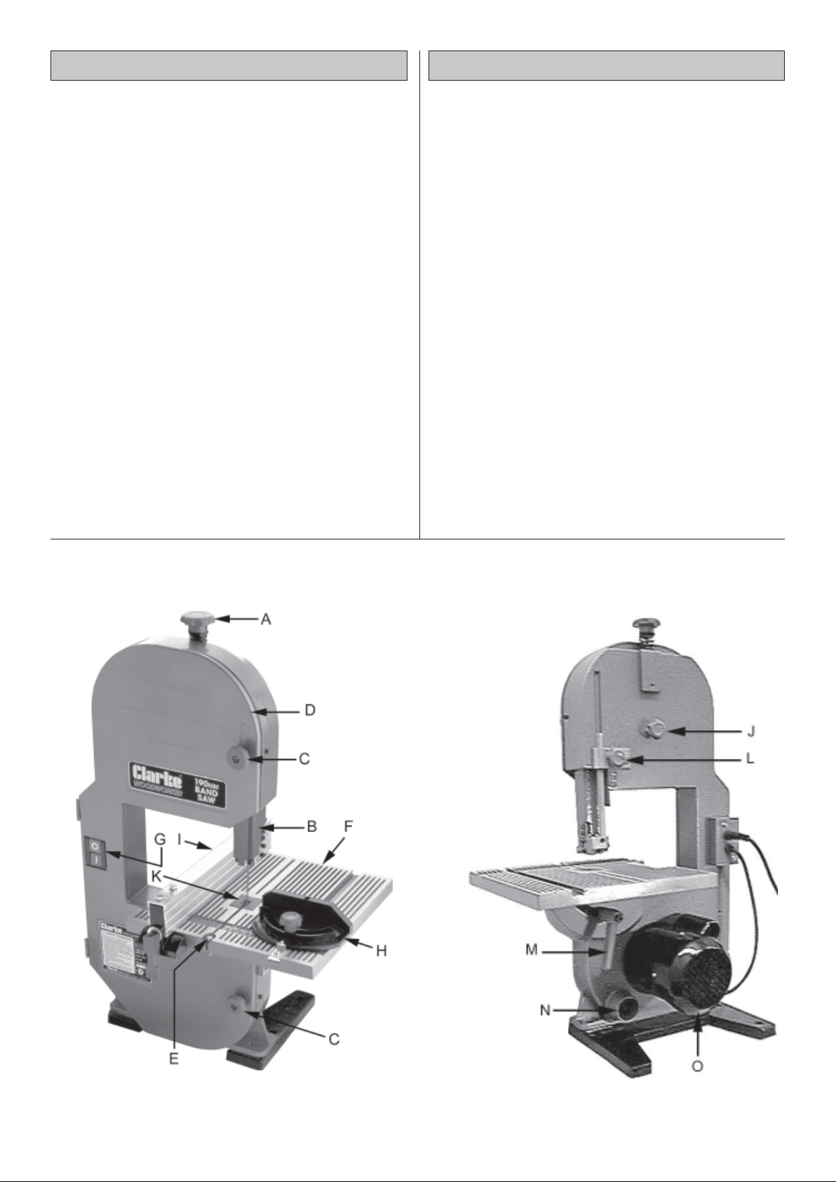
(Ref. Fig. 1)
A Blade Tension Adjuster Knob
B Upper Guide Block and Blade Guard
Assembly.
C Wheel Cover Knobs
D Wheel Cover
E Table Clamping Screw
F Table
G ON/OFF Switch
H Mitre Gauge
I Parallel (Rip) Fence
J Blade Tracking Adjuster
K Table Insert
L Upper Blade Guard Securing Knob
M Table Securing Handle
N Dust Extraction Outlet
Fig. 1
O Motor
6
Page 7
ASSEMBLY
PREPARATION FOR USE
GENERAL NOTES:
For maximum stability and safety, the Bandsaw should
be bolted firmly to either a workbench, a suitable
stand, or a piece of plywood, 5/8” thick, and the
plywood should be clamped firmly to a workbench,
using ‘G’ clamps, whenever the bandsaw is being
used.
Ensure the saw is located in an area large enough to
allow you to work freely, taking into account the size
of workpiece, and that there should be adequate light.
Never work in your own shadow.
Ensure also that an adequate electrical supply is close
at hand. Take extra care where extension leads are
used...ensure there is no possibility of tripping over the
lead when moving around the work area.
Any protective coating on the Band Saw should
be removed using a cloth moistened with
paraffin.
DO NOT use acetone, petrol or paint thinners.
The saw is fully assembled, except for attaching
the table as follows:
All adjustments are factory set, except for those
detailed below which MUST AL W AYS be checked
before switching on the saw.
A. Blade Tension
Blade tension is effected by raising or lowering
the upper wheel, by means of the Blade Tension
Adjuster Knob (A, fig. 1) The upper wheel is
mounted on a spring loaded trunnion, and
tension is therefore a matter of ‘feel’.
Turn the knob clockwise until it becomes tight.
The blade should be taught enough to prevent
slippage, but not overtight, as this will lead to
breakage of the blade.
Additionally, the upper wheel can be adjusted
so that the blade will run centrally about both
wheels. This adjustment is factory set and should
not need to be carried out. If, subsequently, the
blade persists in running off the wheels or runs
off-line, then the adjustment necessary to
overcome this is detailed under ‘Maintenance’.
1. Remove the clamping screw from the table
slot, (E, Fig. 1), and the table insert from the
table, (K, Fig.1).
2. T aking care not to damage the saw blade or
the table, carefully manoeuvre the table, with
the saw blade in the table slot, on to its
mounting.
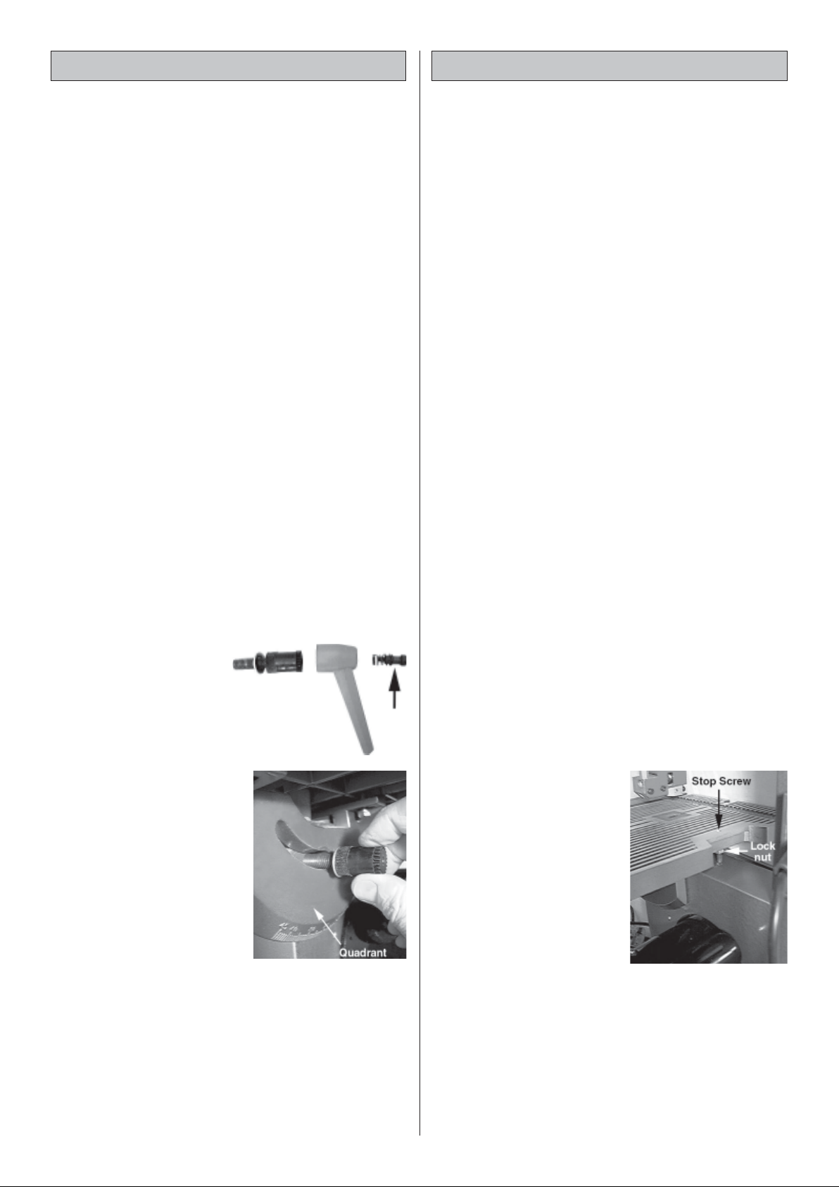
3. Remove the handle
from the table clamping screw by
unscrewing spring loaded screw
arrowed in illustration.
Fig. 2
4. Hold the table firmly so that the
quadrant, on the
underside of the
Fig. 3
table, is flat against
the body of the
saw, with the
curved guide (on
the body of the
saw), engaged in its
slot in the quadrant.
Screw in the
clamping screw as
far as it will go, by hand as shown in Fig. 3.
5. Replace the handle on the clamping
screw ensuring the spring is in place.
6. Replace and tighten the clamping screw in
the slot in the table then replace the Table
Insert.
The parallel fence and mitre gauge may now
be placed on the table.
B. The Table Angle
For all normal sawing operations, it is important
to ensure that the table is set at 90O to the blade.
This is checked by sliding an engineers square
on the table, up to the blade (with the blade
correctly tensioned), and carrying out a visual
inspection.
If necessary slacken off the Table Clamping
Screw, and move the table until you are satisfied
it is square with the blade, then re-tighten the
Clamping Screw.
It may also be necessary
to undo the Table Stop
Screw lock nut (see
Fig.4), and screw the
Stop Screw in or out so
that it just contacts the
body of the machine,
when the table is at 90
to the blade. Nip up the
lock nut when satisfied.
Now, whenever the
table is set to cut Mitres, it is a simple procedure
to reset the table to 90º. i.e. when the stop screw
touches the body, the table is at 90º.
With the Table Clamping Screw tight, check to
ensure the pointer beneath the table, is correctly
set to zero on the scale on the quadrant. If
necessary, slacken the pointer securing screw,
and reset the pointer to zero.
7
O
Fig. 4
Page 8

C. Blade Guide Height
DUST EXTRACTION
The Upper Blade Guide must be adjusted
according to the thickness of the workpiece to
be cut.
Slacken off the Guide Block using knob (L, Fig. 1)
and adjust the height of the guide so that it is no
more that 5mm higher than the workpiece, then
secure in this position.
Check this setting and readjust if necessary
before each cut.
OPERATION
Check to ensure that all safety precautions have
been complied with before switching on the
mains supply and pressing the ON button (1).
Allow the blade to come to full speed.
Ensure the workpiece is held firmly against the
table at all times. (See ‘Tips On Using Your
Bandsaw’ which follows).
Remember that round stock should be clamped
as shown in Fig. 5, to ensure it cannot roll.
Always feed the workpiece at a rate that allows
the blade to cut without difficulty.
Whenever new adjustments are made, you
should always make a trial cut in order to check
the settings.
Parallel Fence and Mitre Gauge
Always use the parallel fence or mitre gauge on
all cuts for which they are intended, to prevent
the blade from running off the cutting guide line,
particularly when working with a tilted table.
When using the parallel fence, there must be
sufficient clearance between the blade and
fence so as to allow the operator to hold the
workpiece firmly, between fence and blade,
without endangering the hand. The other hand
is used as a guide/support ONLY, the hand
between fence and blade being the hand that
feeds the workpiece into the blade.
If the clearance is small, then a push stick should
be used; i.e the workpiece is fed into the blade
with a pushstick.
NOTE:
Pushsticks can easily be made using a piece of wood
1/2”x1” x 12” , with a 1/4” notch cut in one end, as
shown below.
A dust extraction outlet is provided which may
be connected to a vacuum cleaner or a dust
extraction device, such as the CLARKE CDE35,
when the need arises.
Please see your CLARKE dealer for details.
TIPS ON USING YOUR BANDSAW
It should be understood that this machine is
primarily designed for freehand cutting - i.e. to
cut shapes in relatively thin wood. It is NOT
designed for cutting plastics, or any other
material. However, to increase its versatility, it is
possible to cut straight lines using either the Mitre
Gauge or Parallel Fence, as described below.
For all cutting operations, the upper guide block
and blade guard assembly should be adjusted
to be just clear of the work being cut. Not only
does this provide the best safety for the operator,
but it also brings the blade guides closer to the
work giving more accurate results and better
control.
Use both hands to feed the workpiece into the
blade. The work must be held
flat on the table at all times
to prevent binding of the
blade. Use a steady
even pressure just
sufficient to keep
the blade cutting.
Always use a rip fence or mitre guide where
possible to eliminate any sideways slip of the
work. This is most important when the table is
tilted to an angle.
Always plan your work ahead, and aim to make
a complete cut in one pass, rather than stopping
a cut, which requires the workpiece to be
withdrawn. The tradesmans’ rule is “measure
twice, cut once”. It is best to finish a cut in one
continuous operation, but frequent backtracking
may be necessary.
If you do have to withdraw the workpiece, switch
off the bandsaw first, by pressing the OFF (O)
button, and allow the blade to come to a
complete stop before backing it out of the cut.
Remember that the blade removes
material during the cut. This gap
created by the blade is called the
‘kerf’, and must be allowed for
when cutting to exact sizes. Plan
your cut so that the kerf is the scrap
side of the lines you wish to cut. If
necessary, allow a little more for
finish sanding.
8
Fig. 5
Fig. 6
Page 9
RIP SAWING
This term refers to the cutting of the timber with
the grain, rather than at a right angles to the
grain. You can rip wood freehand to a previously
drawn line, but best results are obtained by using
the rip fence.
If the table is set at a level angle, set the rip fence
to the left hand side of the blade for long pieces,
allowing you to use your right hand to support
the work and your left hand, or pushstick to feed
the work into the blade and held firmly against
the fence.
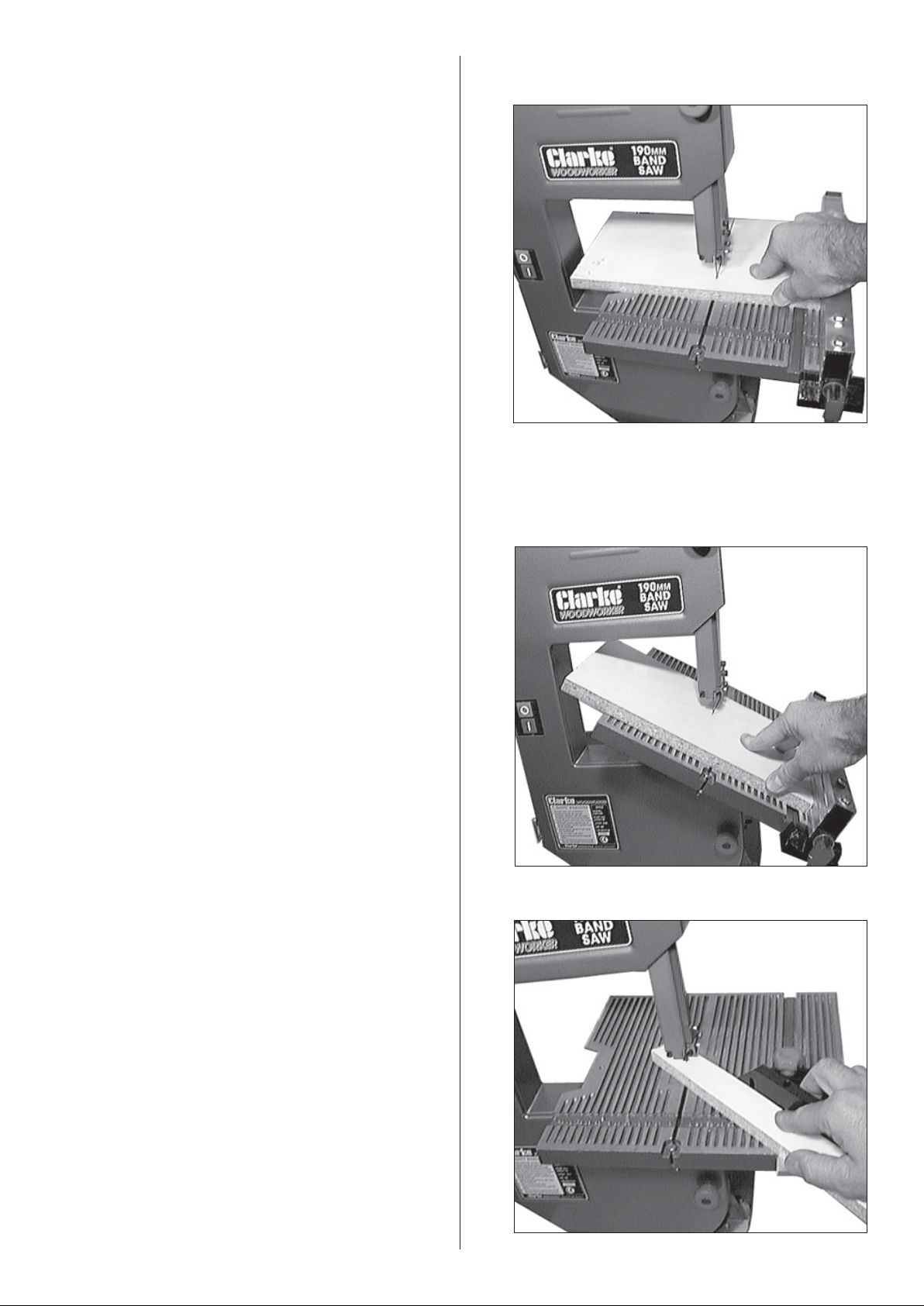
For shorter pieces you may set it to the right as
shown in fig. 7, using your right hand to hold the
work firmly to the table and rip fence.
Fig. 8 shows a similar operation with the table set
to produce a 45º bevel.
CROSS CUTTING
This term refers to cutting timber at right angles to
the grain. This type of cut can also be made
freehand, but the mitre gauge is used to ensure
accurate results. The mitre gauge can be
adjusted to a angles up to 45°, to produce mitre
cuts, or with the table tilted as well - compound
mitre cuts. Make sure the work is held firmly
against the table and against the face of the
mitre gauge. Be careful to keep your fingers
away from the blade, particularly at the end of
the cut.
Slide the Gauge and workpiece together , across
the table with the guide bar engaged in the slot
provided as shown in Fig. 9.
Fig. 7
Fig. 8
NOTE:
In each of the illustrations, for clarity, the left hand has
been omitted, however, in practice it would be used
to support and guide the workpiece, on the opposite
side of the blade, wherever possible.
FREEHAND SAWING
The ease with which many different and varied
shapes can be cut is one of the most important
features of the bandsaw.
When freehand cutting, always feed the work
slowly so that the blade can follow the line you
wish to cut. Make sure not to drag the work off
line, forcing the blade sideways, or twisting it.
In many cases, it is helpful to rough cut about
6mm away from the line. For difficult curves
which may be too tight for the blade, make relief
cuts at 90° to the face of the curve so that these
scraps will fall away as the final radius is sawn.
Fig. 9
9
Page 10
MAINTENANCE
5. Open the Wheel Cover using a screwdriver
on each of the two knob centre screws
ALWAYS disconnnect from the power supply
before carrying out any maintenance
After use
1. Accumulated dust and chips should be
removed from inside the bandsaw. Open the
Wheel Cover and use a brush or vacuum
cleaner at the end of every work session.
2. ALWAYS Lower the Blade Guide Block and
Guard Assembly to its lowest position and lock
it in place.
3. ALWAYS slacken off blade tension.
Periodically
1. Apply a coat of wax paste to the table surface
which will allow the wood stock to glide across
it smoothly and effortlessly.
2. Inspect electric cables to ensure they are not
cracked or damaged in any way. Damaged
cables should be renewed immediately.
3. Inspect the blade for damaged teeth. If any
are broken, the blade should be renewed.
BLADE RENEWAL
1. Disconnect the mains cable from the supply.
2. Slacken off blade tension fully, using the
adjuster knob on top of the machine.
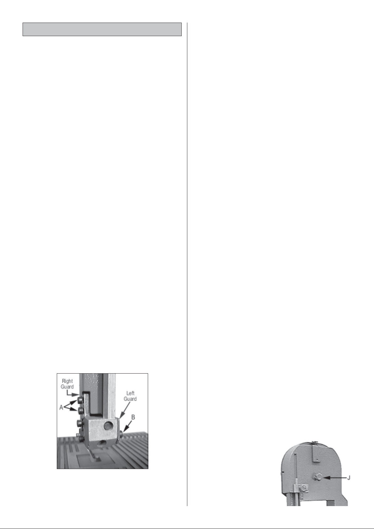
3. Remove both halves of the Upper Blade
Guard by removing the screws at B, Fig. 10 ,
sufficient for the left half of the guard may be
removed, and slackening off screws A, fig 10,
so that the right half may be removed.
4. Remove the Table Insert and the Clamping
Screw, within the table slot, then remove the
table.
Fig.10
6. Ease the blade off the upper and lower
wheels, taking care that the blade does not
‘spring’ as this could cause serious injury. It is
advisable to wear proper clothing, i.e.
industrial gloves, long sleeves and goggles.
7. Refer to Figs. 12 and 13, and using the Hex.
wrench provided, slacken off the screws ‘A’
and ‘G’. This frees the two Blade Support
Bearings, the upper one of which is shown at
‘E’.
Move the bearing ‘E’, and the Lower Guide
Block (H), backwards as far as possible.
8. Slacken off the screws shown at ‘B’ and ‘D’.
This frees the Blade Guides shown at ‘C1 and
C2’....move them away from each other to
provide a gap..
9. Replace the new blade - over the lower
wheel first.
NOTE: It may be necessary to slacken of the brush
mountings in the lower left corner of the wheel housing
in order to manoeuvre the blade between brush and
wheel rim.
Ease the blade over the upper wheel and
through the Blade Guide Block assemblies,
ensuring the teeth point down towards the
table.
10. Try as far as possible to align the blade so that
it runs as near central on the wheels as
possible, then apply tension by turning the
Blade Tension Adjuster Knob clockwise until
the blade feels firm on its run between the
two wheels, but do not overtighten.
11. Readjust the brush if previously moved, or if
not, check to ensure it is brushing firmly up
against the wheel.
NOTE: The brush is responsible for bringing the wheels,
and hence the blade, to a quick stop when the
machine is switched off.
NOTE: Removal of the upper blade guards and table
not only simplifies the blade removal process but also
gives easy access to the various components which
will subsequently require adjusting.
12. Carry out all adjustments, i.e. Blade tracking
and Blade Guide Bearings, as follows:
A. Blade Tracking
Fig. 11
It is important that the
blade runs centrally
about the upper and
lower wheels. Note that
the upper wheel carries
a rubber tyre which has
a convex outer surface.
It is important therefore
to ensure the blade runs
10
Page 11
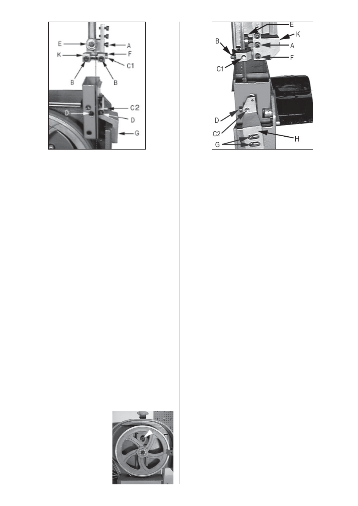
Fig. 12 Fig. 13
exactly in the centre of the tyre. This adjustment
is effected by turning the Tracking Adjuster Knob
(J, Fig. 11).
Screwing ‘in’ (clockwise), will cause the upper
wheel to tilt inwards at the top slightly, which in
turn causes the blade to run on the front of the
wheel. Screwing anticlockwise, has the opposite
effect.
The sequence of adjustment is as follows:
Ref: Fig’s. 12 and 13
1. Apply tension to the blade by screwing the
tension adjuster knob clockwise until the blade
feels firm on its’ run between the two wheels.
2. Turn the upper wheel clockwise, by hand, and
observe the reaction of the blade, and its
position on the tyre of the upper wheel
3. If the blade begins to move towards the front
edge of the tyre, (i.e. towards you as you look
at it), slowly turn the adjuster knob anticlockwise, causing the upper wheel to tilt
outwards at the top, thereby causing the
blade to move further towards the back edge
of the tyre. Conversely, if the blade tends to
run towards the back edge of the tyre, turn
the alignment knob clockwise.
Tracking is correct when the blade runs
precisely in the middle of the wheel.
Fig. 14
IMPORTANT:
It is essential that this
adjustment is carried out
correctly, as it has a direct
bearing on the ability of
the saw to cut in a straight
line.
NOTE:
Should you have difficulty in moving the tension
adjuster, it is possible that the Guide Screw, (arrowed
in fig 14) is too tight. Slacken it off slightly using the
Hex. wrench supplied, to free off the mechanism. Do
not leave this screw too loose, it should be firm, but
the trunnion must be free to move up and down.
When tracking is correct, it is necessary to adjust
the Blade Guides as follows:
B. Blade Guide Adjustments.
(Ref Figs 12 & 13)
NOTE:
a. Blade Guides should be inspected regularly for
wear or chipping. When replacing guides replace
all guides at the same time, both upper and lower.
b. In order to obtain satisfactory results, it is important
that the Blade Guide adjustments are properly
maintained at all times. Before carrying out these
adjustments, the blade must be correctly
tensioned, and tracking properly.
1. Upper Blade Guides
The Guide Block (K), carries the Blade Guides
(C1) and the Blade Support Bearing (E).
The Blade Guides provide side support for the
blade, and are adjusted as follows:
1.1 Lower the Upper Guide Block to its lowest
position and secure it.
Check the position of the Blade Guides. They
should be positioned so that they run in the
middle of the flat portion of the blade and
must NOT come into contact with the teeth
(see Fig.15).
Slacken off the screw (F), if necessary, using
the Hex. wrench provided. This allows the
guide housing to move in or out as required
11
Page 12
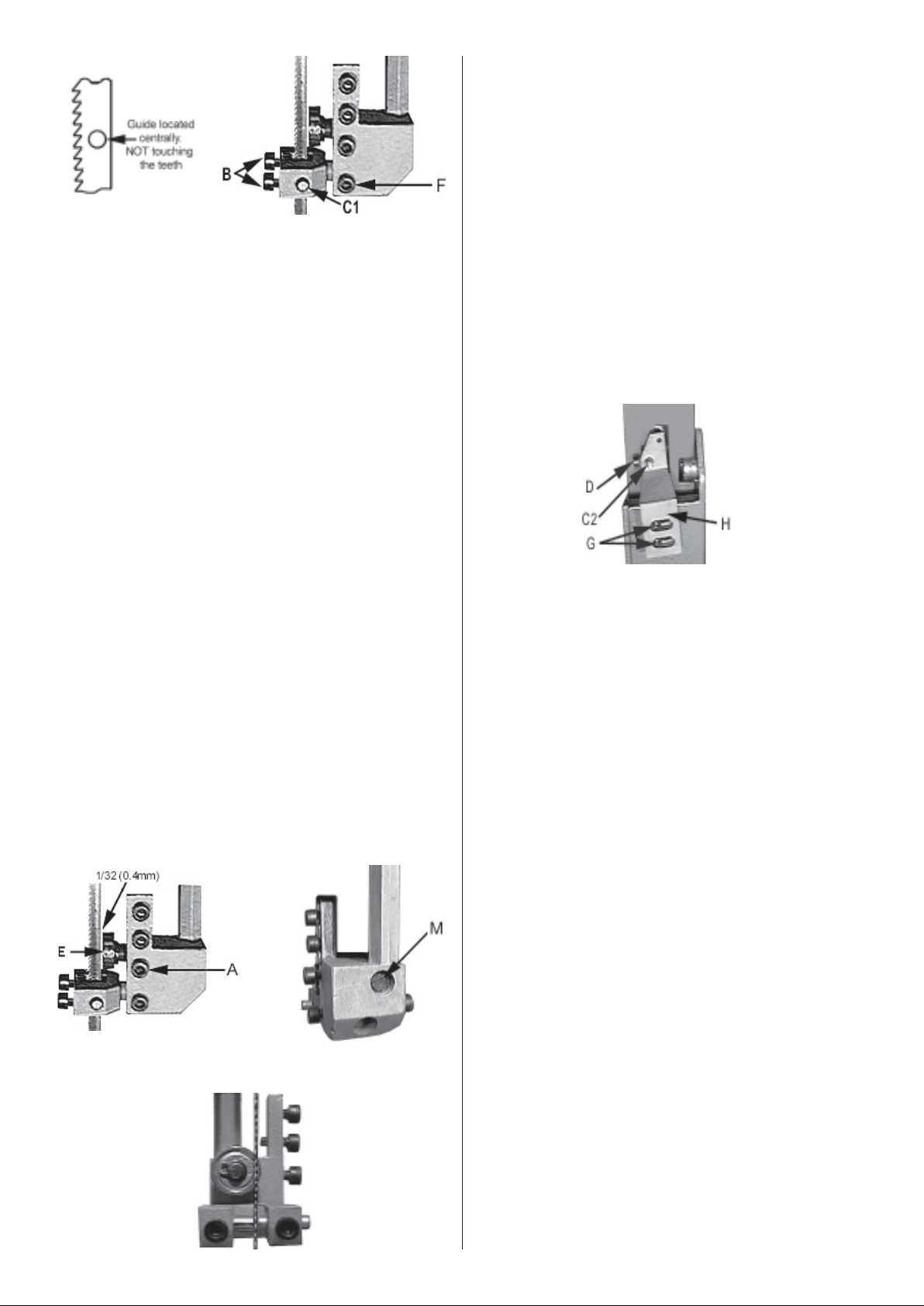
Fig. 15
until the guides (C1) are positioned correctly.
When correctly aligned, re-tighten screw (F).
1.2 Slacken off the two screws (B), securing the
Blade Guides (C1), and position each guide
in turn so that it lightly touches the side of the
blade. Secure firmly in this position by retightening the screws (B).
Simultaneously, slide the bearing to within 1/32”
(0.4mm)of the back of the blade (shown in
fig.16).
Re-tighten screw (A) using the Hex. wrench
provided when completely satisfied.
2. Lower Blade Guides
Ref: Fig.18
The manner of adjustment is similar to that for the
upper blade guides....however, it is necessary to
check the position of the Blade Support Bearing FIRST .
The sequence of adjustment is as follows:
2.1 Slacken the lower blade guide securing
screws (D) (if not already loose).
Turn the upper wheel to ensure the blade is
not pinched or that it is not being pushed to
one side by a maladjusted guide. If necessary,
repeat the process until completely satisfied.
With the Guides correctly set, it is now necessary
to adjust the Upper Blade Support Bearing (E).
The Blade Support Bearing, prevents the blade
from being pushed backwards, and protects it
from tooth damage.
This bearing is adjusted as follows:
(Ref Figs 16)
1.3 With screw ‘A’ , (which secures the shaft
carrying The Blade Support Bearing ‘E’),
slackened, turn the shaft, using a screwdriver
in slot M, so that the blade runs on the edge
of the bearing as shown in fig. 17
NOTE: The bearing is mounted on a cam so turning
the shaft will move the bearing, across the blade.
Fig. 16
Fig. 17
Fig. 18
2.2 Slacken the two Lower Guide Block mounting
screws (G) and position the Guide Block ‘H’
so that the correct clearance of 1/32”
(0.4mm), is achieved between the rim of the
bearing and back of the blade. Re-tighten
the mounting screws (G).
2.3 Adjust the Blade Guides (C2) so that they
lightly touch the side of the blade. Secure
firmly in this position by re-tightening the
screws (D).
2.4 Turn the upper wheel to ensure the blade is
not pinched or that it is not being pushed to
one side by a maladjusted guide. If necessary,
repeat the process until completely satisfied.
2.5 With the upper and lower guides fully
adjusted, the Upper Blade Guard may be refitted, the Wheel Cover closed, using a
screwdriver on the cover knob centre screws,
and the Table r eassembled and replacing the
clamping screw and Table Insert.
2.6 OBSERVING ALL PRECAUTIONS, plug the
machine in to the supply and switch on.
Check for any unusual noises. A harshness in
sound suggests that one or more of the blade
guides is interfering with the blade. This should
be investigated and rectified before use.
BEARINGS
All bearings used in the construction of your
bandsaw and its motor are sealed and
lubricated for life.
12
Page 13

TROUBLE SHOOTING
ALWAYS disconnect your bandsaw from the power supply when troubleshooting, or carrying out
adjustments or maintenance.
Fault Possible Cause Remedy
Blades break
Motor does not run
1. Faulty alignment (tracking)
2. Blade guides incorrectly adjusted.
3. Feeding the work too fast.
4. Forcing or twisting the blade
around a tight radius.
5. Blade too tight.
6. Dull teeth.
7. Blade is badly welded or brazed.
8. Wrong blade fitted
9. Blade left running when not in use.
1. Fuse blown
2. Plug or Power cable defective
1. Carry out tracking adjustments (p10)
2. Readjust Blade Guides
3. Lower the feed rate
4. For tight curves, make relief cuts,
fairly close together, at 90º to the
curve
5. Relieve blade tension
6. Renew blade
7. Renew blade
8. Fit only Quality blades supplied by
Clarke Int’l
9. ALWAYS switch machine OFF when
not in use
1. Renew fuse. If condition persists,
consult your Clarke dealer
2. Renew/Repair plug/Power
cable
3. Motor defective
Machine vibrates 1. Mountings loose
2. Table loose
3. Motor loose
4. Mounting platform is not robust
enough
Blade runs off cutting line
1. Blade Guides incorrectly adjusted
2. Blade tracking maladjusted
3. Blade tension too loose
4. Wrong blade fitted..too thin
3. Consult your Clarke dealer
1. Tighten Mountings
2. Secure table
3. Secure motor mountings
4. Ensure workbench or platform is
of strong enough construction to
fully support the machine
1. Readjust Blade Guides
2. Carry out tracking adjustment (p10)
3. Re-tension blade
4. Fit correct blade
13
Page 14
PARTS LIST & DIAGRAM
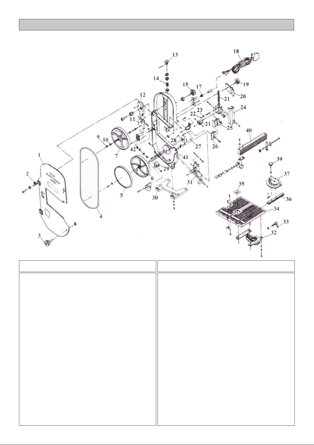
No. Description Part No.
1 Side Cover HT190001
2 Hinge HT190002
3 Side Cover Knob HT190003
4 Saw Blade HT190004
5 Rubber Tyre HT190005
6 Drive Wheel HT190006
7 Driven Wheel HT190007
9 Circlip HT190009
10 Bearing HT190010
11 Lower Plate HT190011
12 Upper Plate HT190012
13 Blade tension Adjuster Knob HT190013
14 Spring HT190014
15 Blade Tracking Adjuster Knob HT190015
17 Cable Grommet HT190017
18 Power Cable HT190018
19 Upper Guard Fixing Knob HT190019
20 Clamping Plate HT190020
21 Upper Guide Block HT190021
No. Description Part No.
22 Circlip HT190022
23 Bearing HT190023
24 Upper Blade Guard complete HT190024
25 Lower Blade Guard complete HT190025
27 Motor HT190027
29 Brush complete HT190029
30 Stand HT190030
31 Lower Guide Block HT190031
32 Quadrant HT190032
33 Table Clamping Screw complete HT190033
34 Table HT190034
35 Table Insert HT190035
36 Guide bar HT190036
37 Mitre Gauge complete HT190037
39 Mitre Gauge Adjuster Knob HT190039
40 Parallel/Rip Fence complete HT190040
41 Casing HT190041
42 ON/OFF Switch complete HT190042
14
Page 15

When disposing of this product, do not dispose of with general waste. It must be disposed of according to the laws governing Waste
Electrical and Electronic equipment, at a recognised disposal facility.
15
Page 16

 Loading...