

Page 1
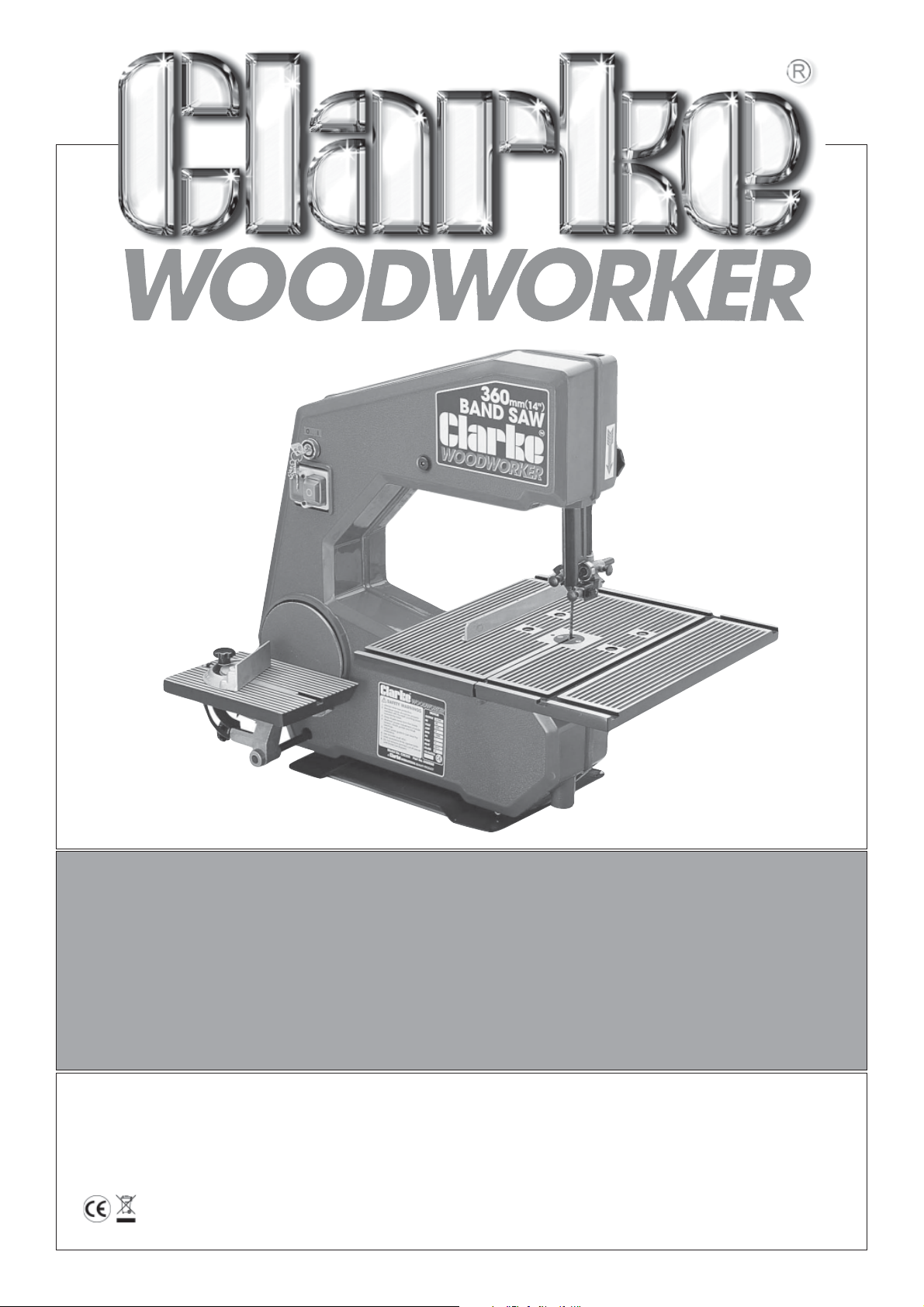
360mm (14")
360mm (14")
BAND SAW
BAND SAW
Model No. CBS 355
Part No. 6460080
Operating and Maintenance
Instructions
0607
Page 2
SPECIFICATIONS
Maximum Cutting Height.................................................. 145mm (5½”)
Throat Depth....................................................................... 360mm (14")
Motor ................................................................................... 230V 50Hz 1 Phase
Power Rating ............................................... 0.375kw
Current Rating ............................................. 4 amp
Speed Rating ............................................... 1500RPM
Blade Size ............................................................................ 1780 ± 3mm (70" ± 0.1")
Width ............................................................. 6mm (¼”)
No. Teeth ...................................................... 6 TPI
Speeds ................................................................................. 3 (160, 750, 1200 m/min)
(8.8, 41.0, 65.6 ft/s )
Table Size............................................................................. 400 x 400mm (15¾” x 15¾”)
Table Tilt ............................................................................... 0 - 45
Sanding Disc Size ............................................................... 15mm (6")
Sanding Disc Table Size ..................................................... 230 x 155mm (9" x 6½”)
O
Sanding Disc Table Tilt ....................................................... 0 - 45
Noise Level .......................................................................... 80db (operating)
Net / Gross Weight ............................................................. 30 / 32 kg (65 - 70lbs)
When disposing of this product, do not dispose of with general waste. It must be disposed of according
to the laws governing Waste Electrical and Electronic equipment, at a recognised disposal facility.
SPARE PARTS AND SERVICE CONTACTS
For Spare Parts and Service, please contact your nearest dealer,
or CLARKE International, on one of the following numbers.
PARTS & SERVICE TEL: 020 8988 7400
PARTS & SERVICE FAX: 020 8558 3622
or e-mail as follows:
PARTS: [email protected]
SERVICE: [email protected]
2
Page 3

Thank you for purchasing this CLARKE Bandsaw and Sander.
Before attempting to operate the machine, please read this instruction manual thoroughly, and follow
all directions carefully. By doing so you will ensure the safety of both yourself and others around you,
and at the same time, you should look forward to long and trouble free service from your Bandsaw.
GUARANTEE
This CLARKE product is guaranteed against faulty manufacture for a period of 12 months from the
date of purchase. Please keep your receipt which will be required as proof of purchase. This guarantee
is invalid if the product is found to have been abused or tampered with in any way, or not used for the
purpose for which it was intended.
Faulty goods should be returned to their place of purchase, no product can be returned to us without
prior permission. This guarantee in no way effects your statutory rights under common law.
CONTENTS Page
Specifications ....................................................................................................................... 2
General Safety Precautions .................................................................................................. 3
Additional Safety Precautions for Bandsaws / Disk Sanders ............................................ 6
Power Supply / Electrical Circuit Diagram .......................................................................... 7
Main Component Illustration and List of Loose Items ........................................................ 8
Assembly .................................................................................................................................. 9
Tips on Bandsaw Blades ........................................................................................................ 10
Operation ................................................................................................................................ 11
Changing Speeds ....................................................................................... 11
Changing Blades ........................................................................................ 12
Use of Accessories .................................................................................................................. 13
Mitre Guide .................................................................................................. 13
Rip Fence ..................................................................................................... 13
Circle Cutting Attachment ........................................................................ 13
Power Belt Sanding ................................................................................................................ 13
Power Disc Sanding ............................................................................................................... 14
Aligning Sanding Disc Table ................................................................................................. 14
Maintenance .......................................................................................................................... 15
Tips on Bandsaw Use .............................................................................................................. 15
Ripsawing ..................................................................................................... 15
Cross Cutting ............................................................................................... 15
Freehand Cutting ....................................................................................... 16
Consumables .......................................................................................................................... 16
Parts List & Diagrams .............................................................................................................. 17 - 19
3
Page 4
GENERAL SAFETY RULES FOR OPERATING MACHINERY
WARNING:
As with all machinery, there are certain hazards involved with their operation and use. Exercising
respect and caution will considerably lessen the risk of personal injury. However, if normal safety
precautions are overlooked or ignored, personal injury to the operator or damage to property, may
result.
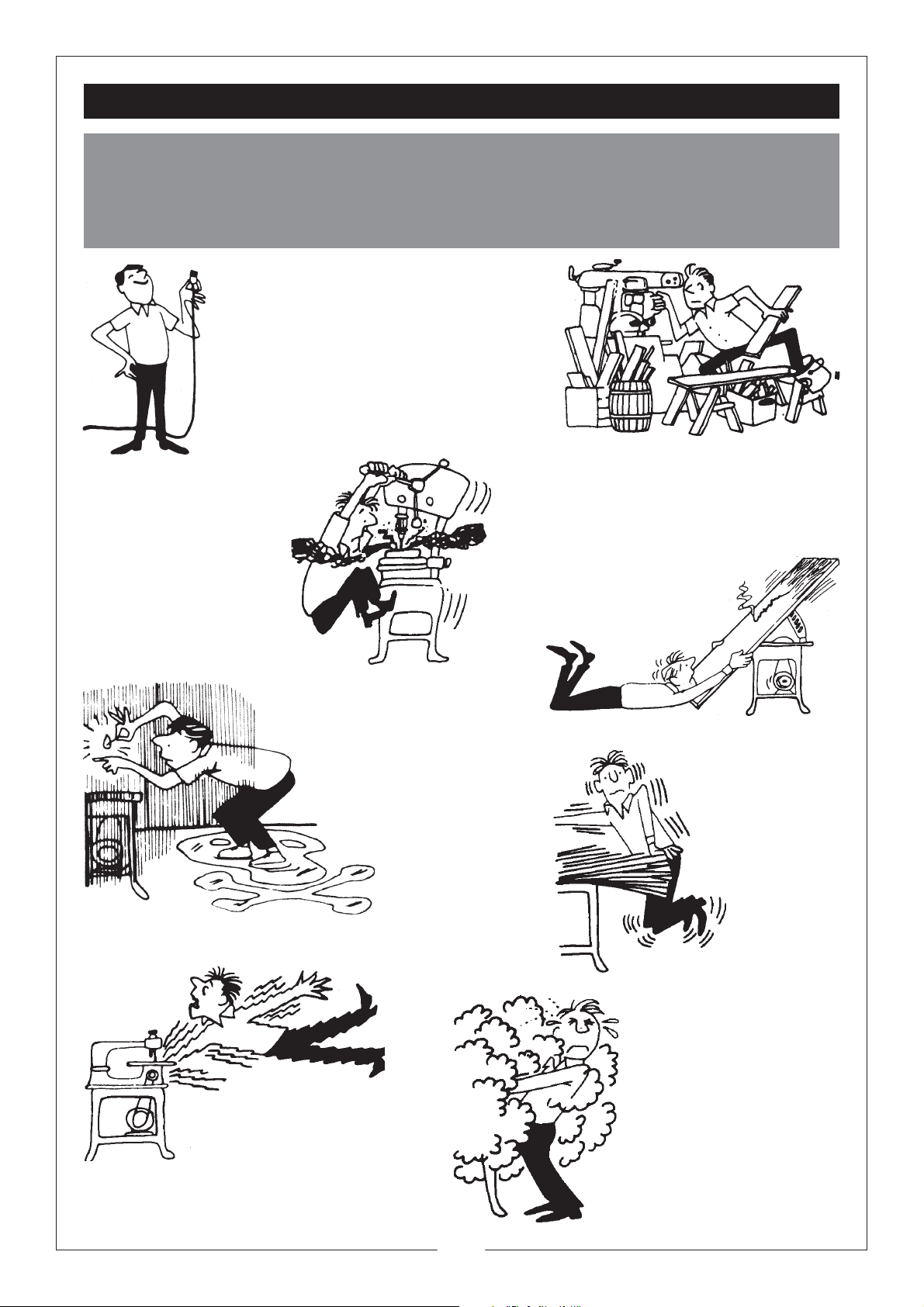
DISCONNECT the
•
MACHINE from the
power supply before
servicing, making
adjustments or when
changing accessories such
as blades, etc.
KEEP WORK AREA CLEAN. Cluttered areas
•
and benches invite accidents.
DON’T FORCE THE
•
MACHINE.
It will do a better and
safer job at the rate for
which it was designed.
DON’T OVERREACH.
•
Keep your proper footing and balance at all times.
For best footing, wear rubber soled
footwear. Keep floor clear of oil,
scrap wood, etc.
AVOID DANGEROUS
•
ENVIRONMENTS
Don’t use power machines in damp or wet
locations or expose them to rain.
Keep your work area well illuminated.
DO NOT USE in explosive atmosphere
(around paint, flammable liquids
etc.).
EARTH ALL MACHINES. If the
•
machine is equipped with three-pin
plug, it should be plugged into a three-pin electrical
socket. Never remove the earth pin.
ENSURE THE
•
WORKPIECE IS
COMPLETELY
SECURE before
switching ON.
NEVER hold a
workpiece by
hand alone.
AL WAYS WEAR SAFETY
•
GOGGLES,
manufactured to the latest
European Safety Standards.
Also use face or dust mask if
cutting operation is dusty.
Everyday eye glasses do not
have impact resistant lenses,
they are NOT safety glasses.
4
Page 5
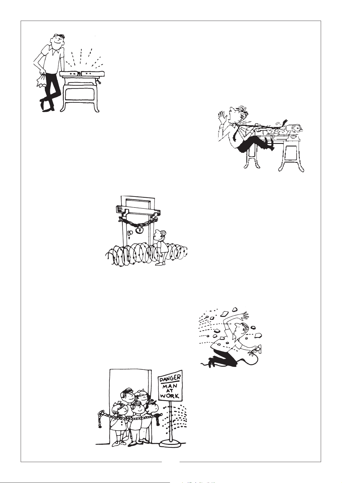
MAINT AIN MACHINE IN T OP
•
CONDITION.
Keep tools sharp and clean
for the best and safest
performance. Follow
maintenance instructions.
CHECK for DAMAGE. Before using the machine, any
•
damaged part, such as a guard etc., should be checked to
ensure that it will operate properly, and perform its
intended function. Check for alignment of moving parts,
breakage of parts, mountings, and any other condition
that may affect the machines’ operation. Any damage
should be properly repaired or the part replaced. If in
doubt, DO NOT USE the machine. Consult your local
dealer.
MAKE YOUR WORKSHOP
•
CHILDPROOF.
With padlocks, master switches
where appropriate, or by
removing starter keys etc.
AL WA YS ensur e that ADEQUA TE LIGHTING is
•
available. A minimum intensity of 300 lux should be
provided. Ensure that lighting is placed so that you will
not be working in your own shadow.
READ and BECOME FAMILIAR with the entire
•
operating manual. Learn the machines applications and
limitations as well as the specific potential hazards
peculiar to it.
WEAR
•
PROPER
APP AREL.
Loose
clothing or
jewellery may
get caught in moving
parts. W ear protective
hair covering to contain long hair.
ALWAYS WEAR EAR PROTECTORS/
•
DEFENDERS.
Considerable noise is generated by this type of
equipment.
Ear protection should be used at all times
HANDLE WITH EXTREME CARE
•
Whenever transporting or installing machinery,
and always use a lifting tool.
DRUGS, ALCOHOL, MEDICATION. Do not operate
•
machine while under the influence of drugs, alcohol or any
medication.
ALWAYS KEEP GUARDS in place and in working order.
•
NEVER ST AND ON THE MACHINE. Serious injury could
•
occur if the machine is tipped or if a cutting tool is accidentally
contacted. Do not store materials above or near a machine, such
that it is necessary to stand on the machine to reach them.
KEEP CHILDREN AWAY.
•
All visitors should be kept a
safe distance from the work
area, especially whilst
operating the machine.
USE ONLY RECOMMENDED
•
ACCESSORIES. The use of improper
accessories could be hazardous.
AVOID
•
ACCIDENT AL
STARTING.
Ensure the
switch is OFF
before
plugging in to
mains.
BE A WARE that accidents are caused by
•
carelessness due to familiarity. ALWAYS
concentrate on the job in hand, no matter how
trivial it may seem.
NEVER LEAVE MACHINE RUNNING
•
UNATTENDED. Turn power OFF. Do not
leave machine until it comes to a complete
stop
5
Page 6

ADDITIONAL SAFETY RULES FOR BANDSAWS AND DISC SANDERS
• Use a Push Stick or scrap of wood to do the pushing and guiding, when sawing small pieces
which require the fingers to be close to the blade.
• Set the blade guide/guard assembly as close as possible to the workpiece. Switch off the saw,
and make sure the blade has come to a complete stop before clearing sawdust or offcuts from
the table.
• Keep the saw properly adjusted, paying particular attention to the blade tension and tracking, and
the blade guides.
• Disconnect the saw from the mains supply before removing the front cover.
• Make sure there are no nails or foreign objects in the part of the workpiece to be sawn or sanded
• Be extra cautious with very large or small, or irregularly shaped workpieces. Set up the machine and
make all adjustments with the power OFF.
i.e. - Tilting the table,
- Adjusting the saw blade guard
- Adjusting the saw blade guides
- Adjusting the sanding table
- Adjusting the Blade tension
- Adjusting the Blade tracking, etc.
• DO NOT operate the machine with the covers off. They must all be in place and securely fastened
when performing any operation.
• Any adjustable component must be securely locked in position to ensure it cannot vibrate free during
operation.
• When sawing curves, make relief cuts to allow removal of scrap material. This will prevent undue
twisting or binding of the saw blade. Make the relief cuts before starting the curved cut. When sawing,
hold material firmly, and feed into blade at a moderate speed.
• Be sure to use the correct blade size and type.
• DO NOT saw any material that does not have a flat surface on which to bear, unless a suitable support
is used.
• The Bandsaw housing is made from plastic. Keep naked flames or hot tools away, as they could
cause serious damage.
• Ensure the bandsaw is permanently and securely fixed in position before operating. DO NOT operate
the bandsaw without the sanding disc guard in place.
• DO NOT operate the disc sander without the sanding table in place.
• Ensure that the sanding disc table is within 1/16 “from the disc AT ALL TIMES, to prevent the workpiece
or fingers being pinched between the table and disc.
• Trim the disc when it becomes frayed, to avoid distraction.
• Only exert moderate pressure when using the belt or disc sander. Pressing too hard will not remove
material faster.
• When sanding , ensure you use the correct grit size for the job.
• Never wet the abrasive as water entering the machine could cause an electric shock.
• DO NOT use the disc sander with the bandsaw blade in place.
IMPORTANT.
This machine is designed primarily for sanding and cutting wood. DO NOT use for sanding asbestos,
painted surfaces, or materials which produce toxic dust.
DO NOT use for sanding Magnesium, as Magnesium dust is highly flammable.
6
Page 7

POWER SUPPLY
Connect the mains lead to a standard, 230 Volt (50Hz) electrical supply through an approved 13 amp
BS 1363 plug, or a suitably fused isolator switch.
WARNING! THIS APPLIANCE MUST BE EARTHED
IMPORTANT: The wires in the mains lead are coloured in accordance with the following code:
Green & Yellow - Earth
Blue - Neutral
Brown - Live
As the colours of the flexible lead of this appliance may not correspond with the coloured markings
identifying terminals in your plug proceed as follows:
• Connect GREEN & YELLOW coloured cord to plug terminal marked with a letter “E” or Earth symbol
“ ” or coloured GREEN or GREEN & YELLOW.
• Connect BROWN coloured cord to plug terminal marked with a letter “L” or coloured RED.
• Connect BLUE coloured cord to plug terminal marked with a letter “N” or coloured BLACK.
If this appliance is fitted with a plug which is moulded onto the electric cable (i.e. non-rewirable)
please note:
1. The plug must be thrown away if it is cut from the electric cable. There is a danger of electric
shock if it is subsequently inserted into a socket outlet.
2. Never use the plug without the fuse cover fitted.
3. Should you wish to replace a detachable fuse carrier, ensure that the correct replacement is used
(as indicated by marking or colour code).
4. Replacement fuse covers can be obtained from your local dealer or most electrical stockists.
5. The fuse in the plug must be replaced with one of the same rating (5 amps) and this replacement
must be ASTA approved to BS1362.
The maximum length of cable between fuse and supply, should be no greater than 1.5m
NOTE: This is for illustration only. NEVER operate the machine with the cover removed.
7
Page 8
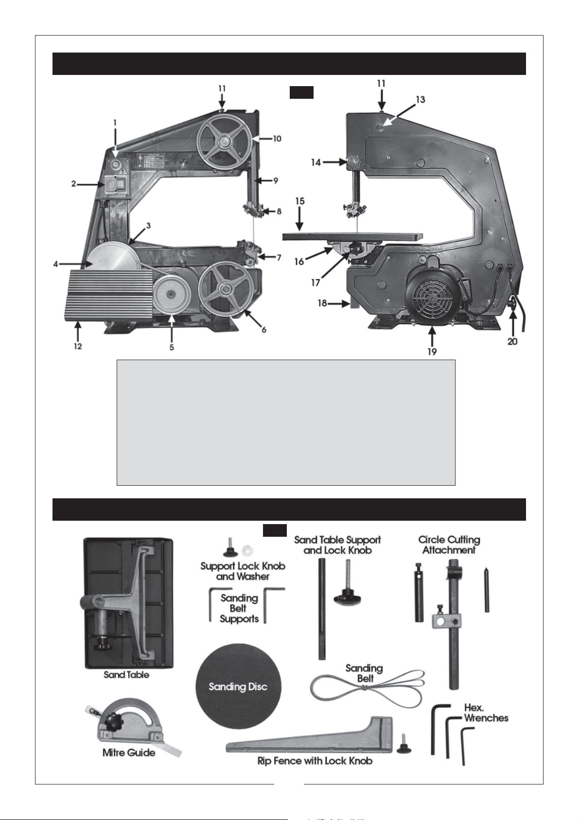
MAIN COMPONENTS
Fig. 1
Fig. 2
1. Power ON/OFF switch lock
2. No volt switch
3. Drive wheel
4. Sanding disc
5. Motor pulley
6. Idler wheel
7 Lower blade guides
8. Upper blade guides
9. Blade guard
10. Tracking wheel
LOOSE PARTS
11. Blade tension bolt
12. Sanding table
13. Blade tracking bolt
14. Blade guard lock knob
15. Work table
16. Quadrant
17. Table lock knob
18. Sawdust extraction outlet
19. Motor
20. Sand Table Support Lock Knob
8
Page 9
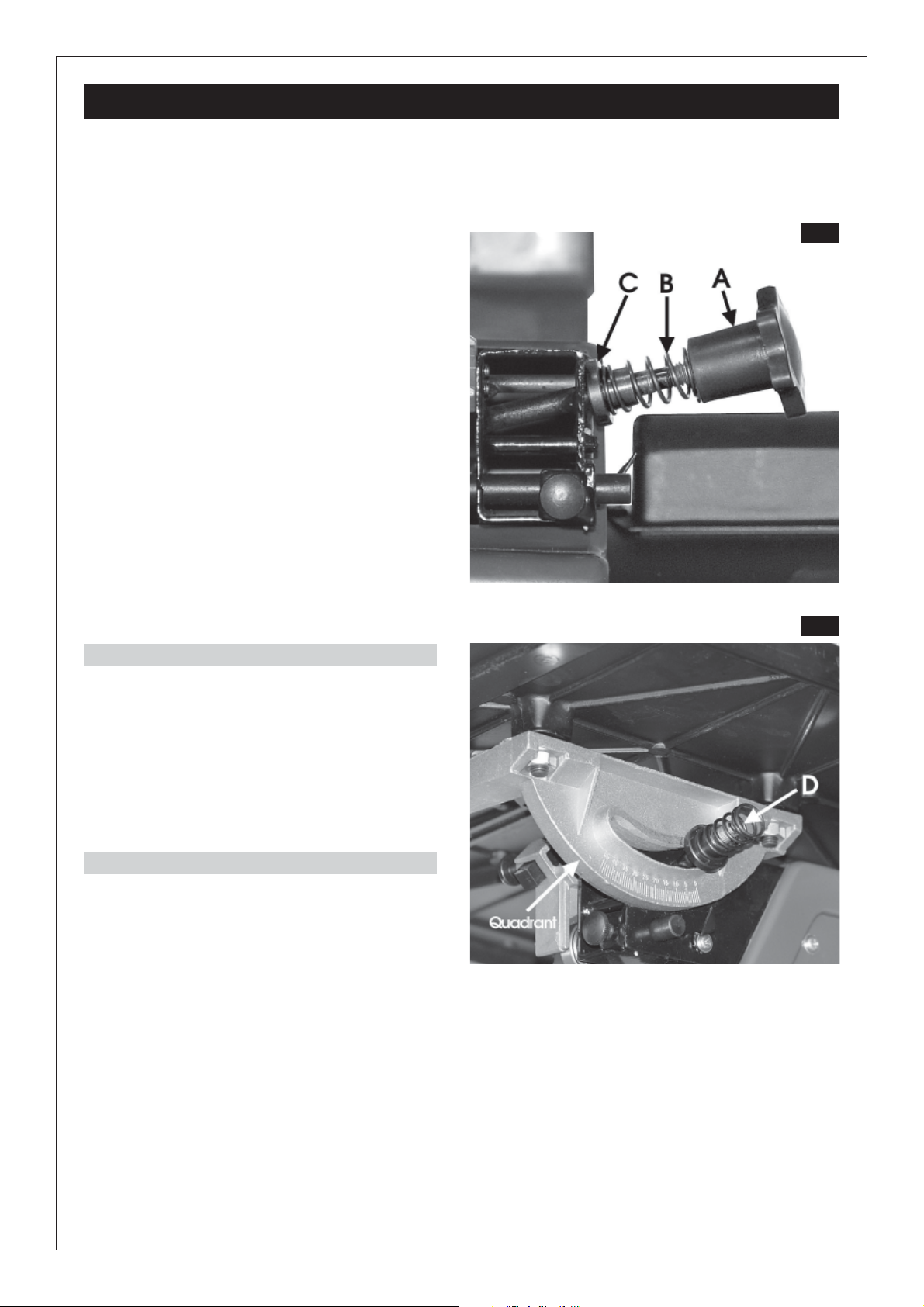
ASSEMBLY
Fig. 4
Fig. 3
Plan your installation. Ensure adequate floor space is available, with good lighting and ventilation,
and an adequate electrical supply is close at hand.
Your bandsaw is supplied fully assembled, except for the work and sanding tables. To assemble the
work table to the bandsaw, proceed as follows:
1. Remove the table lock knob (A), spring (B)
and spring support bush (C) from the table
support at the rear of the bandsaw. (Fig.3).
2. Remove the hex. Socket head screw and
clamp, from the slot on the underside of the
work table.
Standing at the rear of the bandsaw with the
slot of the table facing the blade, fit the table
so that the blade passes through the table
slot, and the support rod (D, Fig. 4) passes
through the curved slot in the Quadrant.
3. Replace the spring support bush (C) with
the large flanged end inwards, towards the
Quadrant.
4. Place the spring (B) over the spring support
bush (C) as shown in Fig.4, then screw on
the lock knob (A). Tighten the knob fully to
ensure the table is firm and stable.
5. Re fit screw and clamp to the table slot.
FASTENING TO A WORKBENCH
(Fixing bolts not supplied)
Your bandsaw should be bolted to a solidly built
work bench. Mounting holes are provided in the
base of the machine. Large flat washers should
be used between the bolt heads and the base
to fasten more securely, and prevent any
damage to the bandsaw. Tighten snugly but do
not overtighten.
Work table
The work table is a 400mm x 400mm aluminium
die casting. It supports the material being cut and
is grooved to accept a mitre guide.
A rip fence is also provided which can be
attached to either the front or rear of the table.
The table can be tilted to any angle from 0 - 45
making possible a large variety of bevel and compound angle cuts. The Quadrant beneath the table is
marked to indicate the angle setting.
The centre of the work table is provided with a table insert, easily and economically replaced if damaged.
O
Illustration shows the Spring and bush
fitted to the support rod
To ensure a square cut, the table must be set at right angles to the blade. To ensure this is so, proceed
as follows.
Raise the blade guard as far as possible, and using a true, small square, check the angle between the
blade and the square. If necessary, slacken off the table lock knob (Item A Fig. 3), and tighten again
when the table is true. Set the pointer to zero on the graduated Quadrant.
9
Page 10
MOTOR
Fig. 5
A ball bearing induction motor is fitted to the bandsaw, powerful enough for all your operating needs.
SAWDUST EXTRACTION OUTLET
It is not essential that this is used, however, if required it can be connected to a vacuum cleaner which
will provide fast and efficient removal of sawdust from your machine.
The vacuum cleaner may be used continuously or intermittently depending upon your requirements.
INTERNAL CONSTRUCTION
The three wheel construction of this bandsaw makes possible the 360mm throat and 145mm depth of
cut capacity within a compact bench mounted unit.
The drive wheel is powered by a belt from the motor pulley. Both the drive wheel and idler wheel are
fixed in position and do not require adjustment.
The tracking wheel (Item 10, Fig. 1) can be adjusted to centre the blade on the three wheels. Because
of the self tensioning feature of this bandsaw, frequent tracking adjustments are not required.
Each wheel is fitted with a rubber tyre to prevent the blade from slipping and to protect the sharp
edges of the blade teeth. These tyres are easily replaced if they become worn.
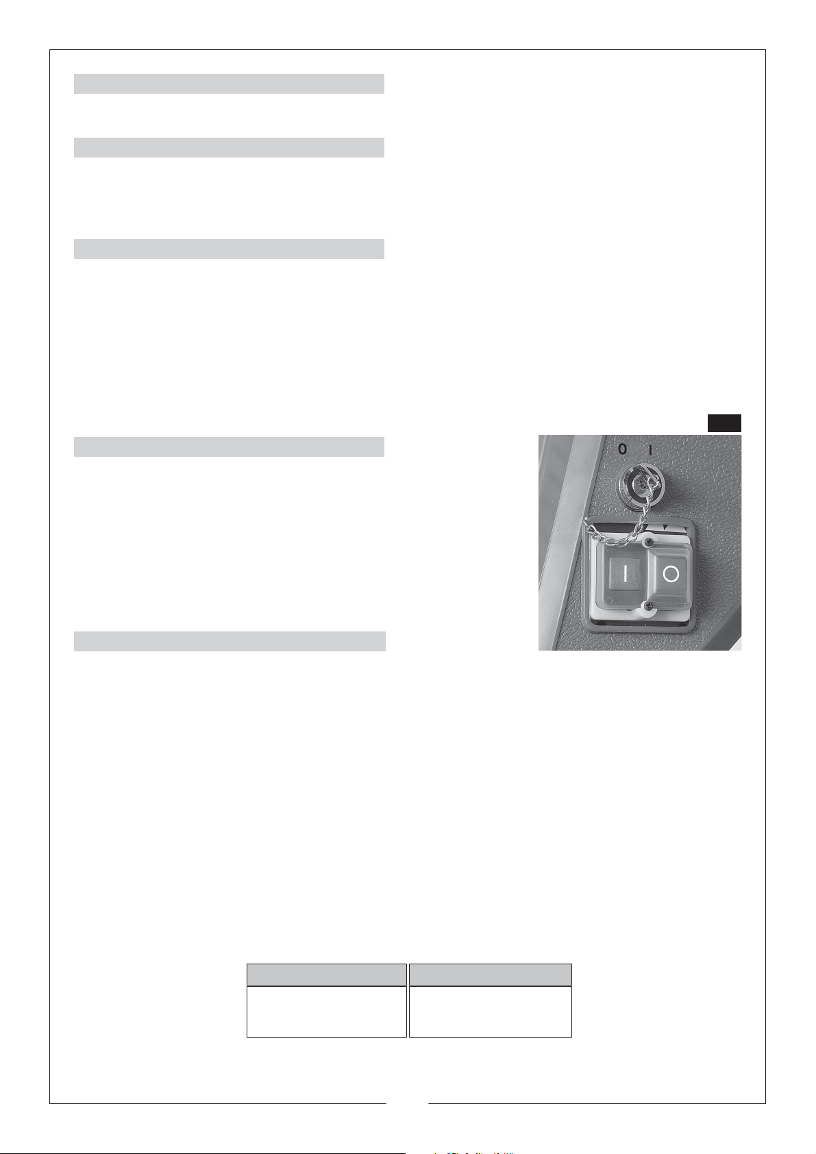
ON/ OFF SWITCH
When the key is in the ‘O’ - locked position it will prevent
unauthorized operation of the bandsaw.
The bandsaw is fitted with a ‘NO VOLT’ switch. In the event of a
power supply failure the bandsaw will have to be manually re
started at the switch when the power is reconnected.
TIPS ABOUT BANDSAW BLADES
The size of a bandsaw blade is denoted by width, length and thickness. This bandsaw uses blades
which are 70" (1780mm) long, 0.015" (0.4mm) thick, and from ¼ - ½” (6mm to l3mm) wide. The number
of teeth per inch and the type of tooth determines the application of the blade.
A wide choice of blades is available for different jobs. There is no general purpose bandsaw blade
which is suitable for all operations.
• Narrow blades will cut to a tighter radius than wider blades.
• Finer toothed blades will make a smoother, but slower cut than coarse blades.
• As a wide blade has more contact with the blade guides, it is easier to cut a true straight line
than with a narrow blade. This is particularly important in rip cutting when the blade has a natural
tendency to follow the grain of the wood:
• For cutting thin or hard materials, the number of teeth per inch needs to be much greater than
for thicker material.
• If the distance between each tooth is greater than the thickness of the material being cut, the
teeth may grab in the work and break off.
The following chart shows recommended blade widths for cutting curves.
Width of Blade Min. Radius of Curve
1/4" (6mm) ½”( l3mm)
3/8" (l0mm) 1"(25mm)
Since it is nearly impossible to resharpen blades, discard all blunt blades. Never attempt to use a bent
or cracked blade.
10
Page 11
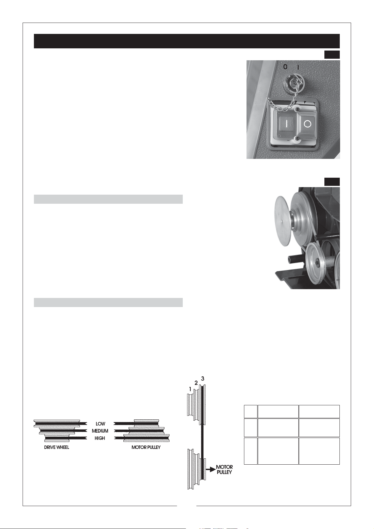
OPERATION
Fig. 6
Fig. 7
1. Turn the key to ‘I’
2. “START”: Push the button marked with “1”.
3. “STOP”: Push the button marked with “0”
4. When the key is in the ‘O’ position, the machine will not
operate. The key may be removed ONLY when in this
position.
It is strongly recommended that when the machine is not in use,
the key is removed and retained in a safe place to prevent the
machines’ use by unauthorised personnel.
REMEMBER
Whenever the side cover is to be removed, the machine MUST be
disconnected from the mains supply and the key removed.
SPEEDS
Your bandsaw is equipped with pulley steps for three speeds, adequate
for all normal working requirements. These are illustrated opposite.
The setting illustrated provides a band speed of 160 metres per minute.
CHANGING SPEEDS
1. Turn the main power switch OFF and disconnect from the power supply.
2. Remove the front cover (unscrew the two hex. socket screws).
3. Refer to the chart below (which is duplicated inside the front cover), and check which pulley
steps to use for the desired speed. Adjust the belt position as required.
4. Replace the front cover.
NOTE: The belt tension is not adjustable, if slipping occurs at any time, the belt should be renewed.
Metres / min
11
1 1200 Sanding
2 750
3 160
Wood
Cutting
Hard
Wood
Cutting
Page 12
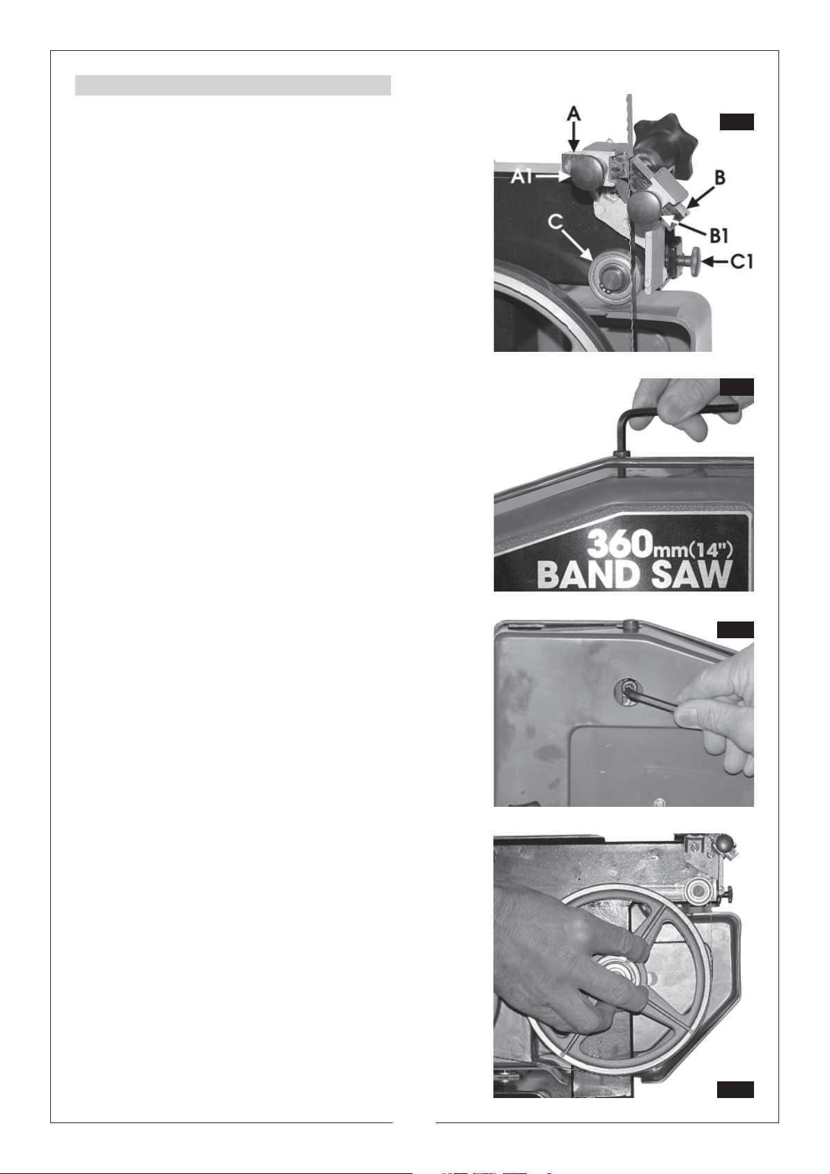
CHANGING BLADES
Fig. 8
Fig. 9
Fig. 10
Fig. 11
1. Turn the SWITCH TO ‘O’ and disconnect from the
power supply. Remove the key from the keyhole.
2. Remove front cover (unscrew the two hex. socket
head screws
4. In both the upper and lower blade guide blocks,
loosen the blade guide locking screws (A1 and
B1) and move the guides away from the blade,
similarly, loosen the lower support bearing locking
screw (C1) and move the bearing away from the
blade.
6. Using the hex key supplied, turn the blade
tensioning bolt clockwise until it is loose, then turn
the tracking adjuster (12, Fig.1) anticlockwise so
that the old blade may be removed.
7. Slip the new blade over the three wheels, so that
the blade is as close as possible to the centre of
the wheels, ensuring the teeth are pointing
towards you and downwards.
Lower blade guide block
Tensioning Bolt
8. Turn the tracking adjuster clockwise until the
wheel is as near vertical as is possible to estimate,
then turn the tensioning bolt until the blade is
taught, but not excessively so.
NOTE:
To prevent the blade from slipping off as you turn the
adjuster bolts, press down firmly on the blade between
the wheels on its longest run.
9. Rotate the idler wheel by hand, whilst turning
the tracking adjuster, until the blade centres
correctly on all three wheels. Turning the
tracking adjuster clockwise will cause the blade
to run on the outside of the wheels anticlockwise will cause it to run on the inside.
10. Slide the blade support bearings (C, Fig. 8), in
both upper and lower guide blocks, so they
lightly touch the rear of the blade, and lock in
place. Similarly, slide all blade guides ( A & B
Fig.8) so that they very lightly touch the blade,
and lock in place.
Tracking Adjuster
Turn the Idler wheel
12. When satisfied, replace the front cover.
12
Page 13
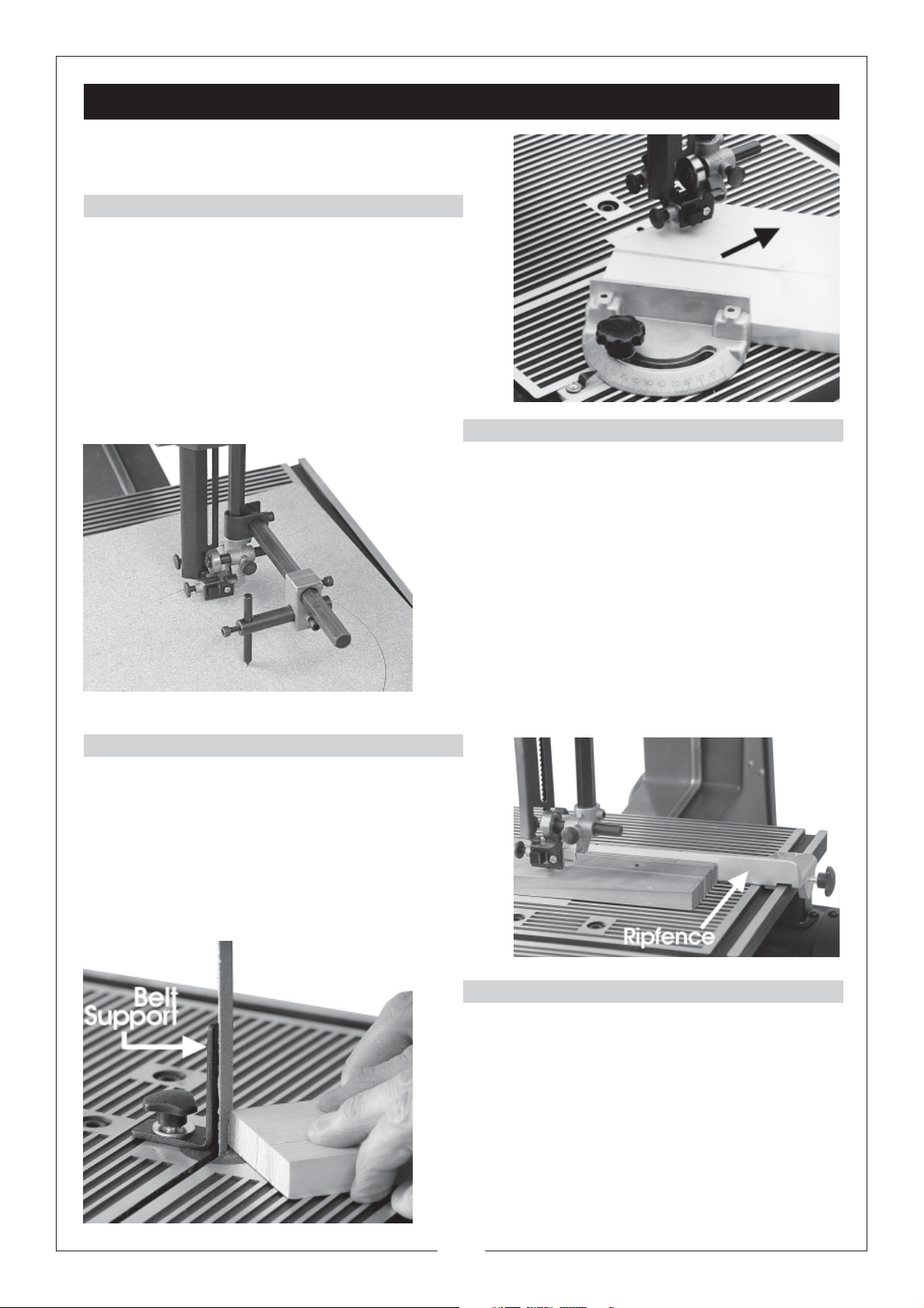
USE OF ACCESSORIES
MITRE GUIDE
Most crosscut work, especially with small pieces is
more easily controlled with the use of a mitre guide
The mitre guide is also essential for accurate mitre
and compound mitre cuts. The guide is graduated
to 45O for both left and right hand angles.
CIRCLE CUTTING ATTACHMENT
The circle cutting attachment mounts on the arm
of the upper guide block. Accurate circles can be
cut with a radius of 50 mm to 200mm. Assemble as
shown in the illustration opposite
Make the first cut to the perimeter of the circle
freehand before setting the pivot pin, into the work.
The pivot pin must be aligned exactly in line with
the blades’ tips. If the pivot is too far back (i.e. to
the rear of the blade), the blade will run outside
the desired circumference - if too far forward, the
blade will run inside the desired circumference.
Ensure the Upper guide block is secured as close to
the workpiece as possible.
RIP FENCE
True, straight line rip cutting, is best done by guiding
the work against the rip fence. On this bandsaw the
fence can be attached to both the front and rear
of the work table, by a single screw which engages
with the end of the table, holding the rip fence firmly
at the desired location.
The fence can also be used for cutting off to exact
widths.
POWER BELT SANDER
Remove the blade and fit a sanding belt.
Make sure that the blade support bearings and
blade guides, (both upper and lower), are secured,
and well clear of the abrasive sanding belt.
Two sanding belt supports are provided. They are
of right angle construction, one with a straight face,
and one slightly curved. Screw the appropriate
support into the threaded hole in the work table,
(near the table insert) with the hex. screw provided.
Adjust the support so that it lightly touches the belt.
13
Page 14
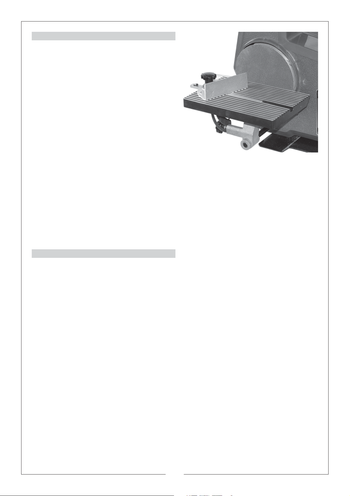
POWER DISC SANDER
1. Remove the saw blade.
2. Remove the sanding disc guard from the front
cover.
3. Fix the abrasive sanding disc in place.
4. Attach the support rod to the Sanding Table
with the two hex. socket head screws provided,
so that the end of the rod is approx. flush with
the end of the bracket, and mount the
assembly on to the bandsaw via. the hole
beneath the sanding disc.
Slacken off the table lock knob (at the back
of the bandsaw) if necessary, to allow the
support rod to be pushed in until the table is
approx. 2mm (1/16") from the sanding disc. Fully
tighten the table lock knob.
The sanding table is ribbed in the same way as the bandsaw work table, to keep saw dust below the
working level. The sanding table is also slotted for use with the mitre guide supplied with your bandsaw.
The sanding table can be tilted to 45O for bevel and compound mitre sanding.
For best results in disk sanding, set the bandsaw at high speed.
Replacement sandpaper discs are available from your CLARKE dealer (See CONSUMABLES on page
19). They can be obtained in three grit sizes and are self adhesive so that no glue is required to fix them
to the aluminium disk.
IMPORTANT: When the sanding disc is not in use, ALWAYS replace the disk guard to avoid the possibility
of accidental contact.
ALIGNING THE SANDING DISK TABLE.
WARNING:
To avoid injury from accidental starting, ensure the machine is unplugged before attempting any
adjustments.
1. Using a true combination square, check the angle of the work table with the disc with the tilt
angle pointer set to 0O.
2. If the table is not true, slacken off the lock knob screw, beneath the table, and adjust so that it
is square with the disk.
3. Retighten the lock knob screw.
4. Reposition the angle pointer to read 0O.
14
Page 15

MAINTENANCE
BEFORE CARRYING OUT ANY SERVICING OR MAINTENANCE, DISCONNECT THE MACHINE FROM THE
POWER SUPPLY
CHANGING TYRES
Eventually the rubber tyres on the bandsaw wheels will wear due to the constant contact of the sharp
teeth of the blade. Lift the edge of the tyre with a small screwdriver and the tyre can be worked off the
wheel easily. We recommend that all three tyres be changed at the same time.
BLADE GUIDES
Blade guides should be inspected regularly for wear or chipping. When replacing guides replace all
guides at the same time, both upper and lower.
BEARINGS
All bearings used in the construction of your bandsaw and its motor are sealed and lubricated for life.
CLEANING
Accumulated dust and chips should be removed from inside the bandsaw frequently. Remove the
front cover and use a brush or vacuum cleaner. At the end of every work session, clean sawdust away
from the motor vents.
TIPS ON USING YOUR BANDSAW
For all cutting operations the upper blade guard should be adjusted to be just clear the work being
cut. Not only does this provide the best safety for the operator, but it also brings the blade guides
closer to the work giving more accurate results and easier control.
Use both hands to feed the workpiece in to the blade. The work must be held flat on the table at all
times to prevent binding of the blade. Use a steady even pressure just sufficient to keep the blade
cutting.
Always use a rip fence or mitre guide where possible to eliminate any sideways slip of the work. This is
most important when the table is tilted to an angle.
Always plan your work ahead. The tradesmans’ rule is “measure twice, cut once”. It is best to finish a
cut in one continuous operation, but frequent backtracking may be necessary.
Turn off the motor and allow the blade to come to a complete stop before backing the blade out of the cut.
Remember that the blade removes material during the cut. This gap created by the blade is called
the ‘kerf’, and must be allowed for when cutting to exact sizes. Plan your cut so that the kerf is the
scrap side of the lines you wish to cut. If necessary, allow a little more for finish sanding.
RIP SAWING
This term refers to the cutting of the timber with the grain, rather than at a right angles to the grain. You
can rip wood freehand to a previously drawn line, but best results are obtained by using the rip fence.
If the table is set at a level angle, set the rip fence to the left hand side of the blade, allowing you to
use your right hand to hold the work firmly against the fence. The width of cut indicator on the front of
the work table shows the distance between the blade and the right hand edge of the timber.
When cutting a bevel rip, with the table tilted at any angle up to 45O, set the rip fence to the right hand
side of the blade if the width of the workpiece allows it.
With the fence on the ‘downhill’ side of the table, it will help support the work against slip. The width of
cut indicator shows the distance between the blade and the rip fence.
CROSS CUTTING
This term refers to cutting timber at right angles to the grain. This type of cut can also be made freehand,
but the mitre guide is used to ensure accurate results. The mitre guide can be adjusted to a 45O angle
to produce mitre cuts, or with the table tilted as well, compound mitre cuts.
Make sure the work is held firmly against the table and against the face of the mitre guide. Be careful
to keep your fingers away from the blade, particularly at the end of the cut.
15
Page 16

SPARE PARTS LIST
Item Description Part No.
1 Frame FM355001
2 Wheel Support FM355002
3 Axle Block FM355003
4 Pin FM355004
5 Bolt FM355005
6 Washer FM355006
7 Nut FM355007
8 Tension Spring FM355008
9 Tracking Bolt FM355009
10 Tension Bolt FM355010
11 Idler Wheel FM355011
12 Wheel Tyre FM355012
13 Ball Bearing FM355013
14 Circlip FM355014
15 Circlip FM355015
16 Drive Wheel FM355016
17 Rear Cover FM355017
18 Screw FM355018
19 Screw FM355019
20 Washer FM355020
21 Front Cover FM355021
22 Hex. Bolt FM355022
23 Washer FM355023
24 Circlip FM355024
25 Lock Knob FM355025
26 Soc. Head Bolt FM355026
27 Pulley Hub FM355027
28 Motor Pulley FM355028
29 Motor FM355029
30 Bolt FM355030
31 Drive Belt FM355031
32 Upper Guide Block FM355032
33 Thumbscrew FM355033
34 Blade Guide FM355034
35 Blade Guide FM355035
36 Thumbscrew FM355036
37 Bearing Shaft FM355037
38 Circlip FM355038
39 Ball Bearing FM355039
40 Lower Guide Block FM355040
41 Blade Guide FM355041
42 Blade Guide FM355042
43 Blade Guide Supp’t FM355043
44 Blade Guard FM355044
45 Screw FM355045
46 Table Insert FM355046
Item Description Part No.
47 Worktable FM355047
48 Nut FM355048
49 Quadrant FM355049
50 Spring Supp’t Bush FM355050
51 Spring FM355051
52 Lock Knob FM355052
53 Pointer FM355053
54 Cable Clamp * FM355054
55 Blade See P18
56 Set Plate FM355056
57 Socket Head Bolt FM355057
58 Plug & Cable * FM355058
59 Hex. Bolt FM355059
60 Sanding Disc See P18
61 Spindle Hub FM355061
62 Aluminium Disc FM355062
63 Bracket Rod FM355063
64 Table Bracket FM355064
65 Sanding Table FM355065
66 Trunnion FM355066
67 Pointer FM355067
68 Sand. Disc Cover FM355068
69 Pivot Mount FM355069
70 Lock Knob FM355070
71 Lock Knob FM355071
72 Set Screw FM355072
73 Socket Head Bolt FM355073
74 Wheel Guard FM355074
75 Low Guard FM355075
76 Screw FM355076
77 Switch Box Base FM355077
78 Scale Ring * FM355078
79 Switch Box FM355079
80 Push Switch 1A FM355080
81 Push Switch 1B FM355081
82 Lock Switch. FM355082
83 Key * FM355083
84 Screw FM355084
85 Dust Cloak FM355085
86 Dust Cloak Cover FM355086
87 Screw FM355087
88 Relay * FM355088
89 Wire Set * FM355089
90 Terminal Block * FM355090
91 Grommet FM355091
* Not shown on parts diagram
17
Page 17
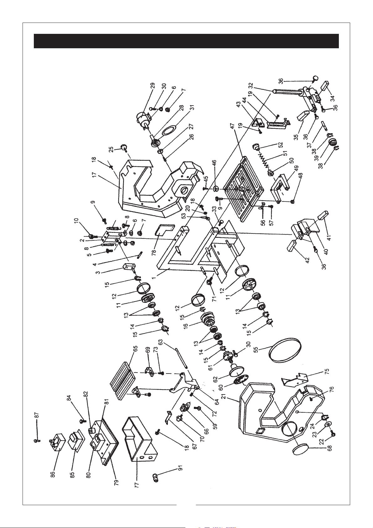
SPARE PARTS DIAGRAM
18
Page 18
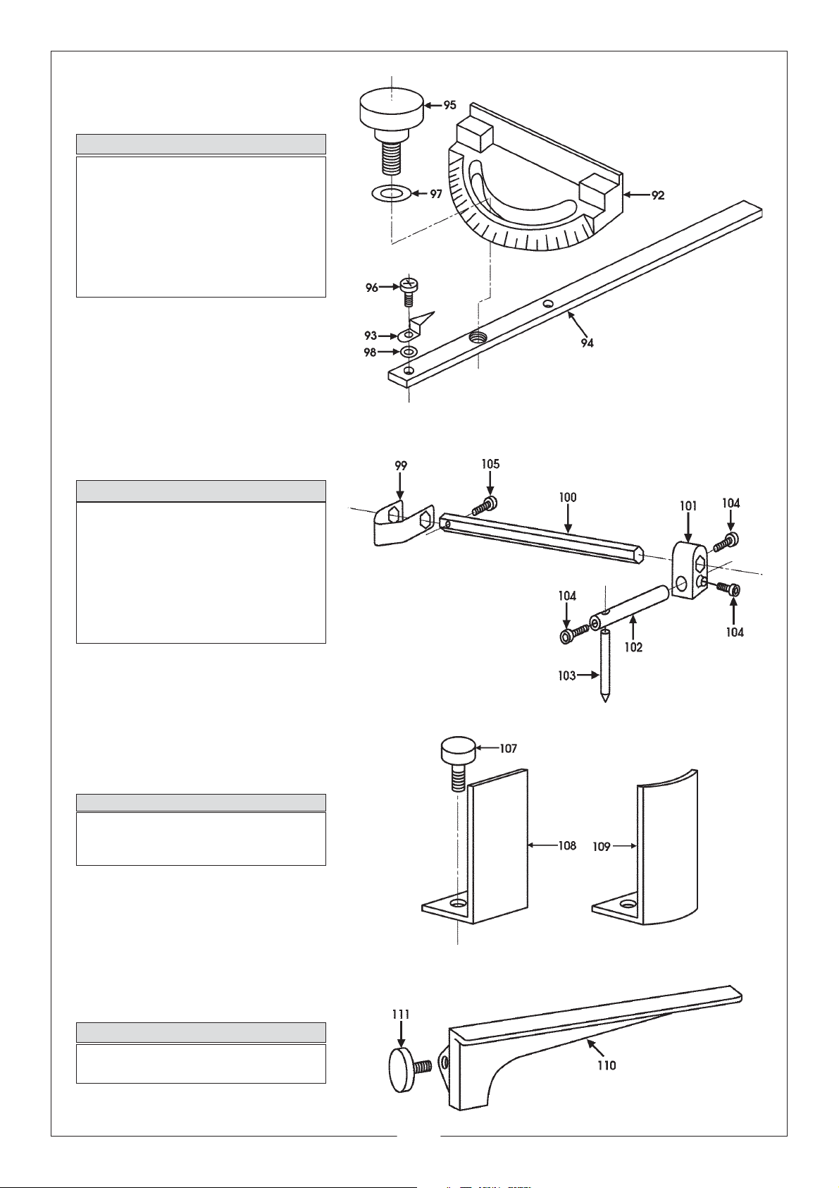
MITRE GUIDE
Item Description Part No.
92 Mitre Gauge FM355092
93 Pointer FM355093
94 Ruler Complete FM355094
95 Lock Knob FM355095
96 Screw FM355096
97 Washer FM355097
98 Washer FM355098
CIRCLE CUTTING ATTACHMENT
Item Description Part No.
99 Clamp FM355099
100 Hex. Bar FM355100
101 Slide FM355101
102 Intermediate Pin FM355102
103 Centre Pin FM355103
104 Screw 3/16"x 9/16" FM355104
105 Screw 3/16"x1" FM355105
SANDING BELT ATTACHMENT
Item Description Part No.
107 Lock Knob FM355107
108 Flat Plate FM355108
109 Rounded Plate FM355109
RIP FENCE
Item Description Part No.
110 Rip Fence FM355110
111 Lock Knob F355111
19
 Loading...