

Page 1
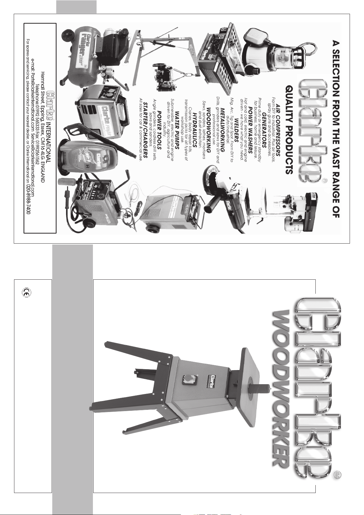
VERTICAL RECIPROCATING SANDER
VERTICAL RECIPROCATING SANDER
OPERATING AND MAINTENANCE
INSTRUCTIONS
0305
MODEL No. VRS1
Part No. 6262035
Page 2
-1- -14-
Please note that the details and specifications contained herein are correct at the time of going to
print. However CLARKE International reserve the right to change specifications at any time without
Faulty goods should be returned to their place of purchase, no product can
be returned to us without prior permission.
This guarantee does not affect your statutory rights.
This guarantee is invalid if the product is found to have been abused or
tampered with in any way, or not used for the purpose for which it was
intended.
This CLARKE product is guaranteed against faulty manufacture for a period
of 12 months from the date of purchase. Please keep your receipt as proof
of purchase.
SERVICE: [email protected]
PARTS: [email protected]
prior notice. Always consult the machines data plate
PARTS & SERVICE TEL: 020 8988 7400
Thank you for purchasing this CLARKE Vertical Reciprocating Sander.
Your new sander is designed for DIY use only.
Before using the machine, please read this manual thoroughly and carefully follow all
instructions given. This is for your own safety and that of others around you, and is also to
help you achieve a long and trouble free service from your new tool.
Please read these instructions carefully before operating the tool
or e-mail as follows:
CLARKE GUARANTEE
A wide range of tools and accessories is available from your nearest CLARKE dealer, for
further information, contact your nearest dealer, or telephone CLARKE International Sales
department on 01992 565300.
dealer.
NOTE: parts marked # are optional and can be obtained from your nearest CLARKE
Accessories
91 LGVRS1091 # 1” Arbor # #
92 LGVRS1092 # 1-1/2” Arbor # #
93 LGVRS1093 # 1-3/4” Arbor # #
94 LGVRS1094 2” Arbor 1
95 LGVRS1095 # 3” Arbor # #
Accessories
90 LGVRS1090 3/4” Arbor 1
PARTS LIST Cont
38 LGVRS1038 Strip Nut M6 2
39 LGVRS1039 Knob 1
40 LGVRS1040 Hex. Nut M6 1
41 LGVRS1041 Bracket II of Worktable 1
42 LGVRS1042 Bracket III of Worktable 1
43 LGVRS1043 Cross Head Screw M8 x 16 2
44 LGVRS1044 Dust Collect Cover 1
45 LGVRS1045 Hex. Nut M5 4
46 LGVRS1046 Cap Screw M5 x 30 2
47 LGVRS1047 Left Core Axle of Worm Wheel 1
48 LGVRS1048 Worm Wheel 1
49 LGVRS1049 Worm Stand 1
50 LGVRS1050 Right Core Axle of Worm Wheel 1
51 LGVRS1051 Hex. Bolt M6 x 16 4
52 LGVRS1052 Fix Frame For Motor 1
53 LGVRS1053 Hex. Nut M8 5
54 LGVRS1054 Hex. Bolt M8 x 25 7
55 LGVRS1055 Lock Washer 8mm 7
56 LGVRS1056 Left Hand Hex. Nut M8 2
57 LGVRS1057 2” Convex Washer 1
58 LGVRS1058 2” Sand Drum 1
59 LGVRS1059 2” Rubber Drum 1
60 LGVRS1060 2” Rubber Drum Washer 1
61 LGVRS1061 Connecting Rod 1
62 LGVRS1062 Key 5 x 5 x50 1
67 LGVRS1067 3/4” Washer 2
68 LGVRS1068 3/4” Sand Drum 1
69 LGVRS1069 3/4” Rubber Drum 1
70 LGVRS1070 3/4” Connecting Rod 1
76 LGVRS1076 Countersunk Screw ST3.5 x 12 10
77 LGVRS1077 Washer Nut M8 4
78 LGVRS1078 Rubber Foot 4
79 LGVRS1079 Switch Seat 1
80 LGVRS1080 Bottom Guard 2
81 LGVRS1081 3-1/2” Core Table Insert 1
Page 3
-13-
37 LGVRS1037 Hex. Bolt M8 x 16 4
8 LGVRS1008 Motor 1
9 LGVRS1009 Motor Shaft Key 5 x 5 x 50 1
4 LGVRS1004 Switch 1
5 LGVRS1005 Hex. Nut M4 1
6 LGVRS1006 Lock Washer 1
7 LGVRS1007 Retaining Ring 1
10 LGVRS1010 Set Screw M6 x 5 2
11 LGVRS1011 Worm 1
12 LGVRS1012 Retaining Ring 55mm 1
13 LGVRS1013 Retaining Ring 32mm 1
14 LGVRS1014 Bearing 80106 1
15 LGVRS1015 Hex. Bolt M8 x 75 1
16 LGVRS1016 Flat Washer 5mm 4
17 LGVRS1017 Rock Arm Pin Bolt 2
18 LGVRS1018 Rock Arm 2
19 LGVRS1019 Guide Column 1
20 LGVRS1020 Shuttle Axle Sleeve 1
21 LGVRS1021 Shuttle Axle 1
22 LGVRS1022 Spring Dowel 4 x 30 1
23 LGVRS1023 Bearing 61804 1
24 LGVRS1024 2-3/8” Core Table insert 1
25 LGVRS1025 2” Core Table Insert 1
26 LGVRS1026 1-1/4” Core Table Insert 1
27 LGVRS1027 Countersunk Screw M5 x 10 2
28 LGVRS1028 Spring Dowel 3 x 8 1
29 LGVRS1029 Work Table 1
30 LGVRS1030 Cross Head Screw M5 x 6 8
31 LGVRS1031 Dust Cover 1
32 LGVRS1032 Hex. Bolt M8 x 20 8
33 LGVRS1033 Flat Washer 8mm 21
34 LGVRS1034 Cross Head Screw M6 x 20 2
35 LGVRS1035 Flat Washer 6mm 7
36 LGVRS1036 Bracket I of Worktable 1
1h LGVRS1001h Hex. Bolt M8 x 25 4
1f LGVRS1001f Cross Head Screw M8 x 16 24
1i LGVRS1001i Washer Nut M8 4
2 LGVRS1002 Flat Washer 4mm 12
3 LGVRS1003 Cross Head Screw M4 x 12 4
1 LGVRS1001 Stand 1
PARTS LIST
Item Part Number Description Qty
1a LGVRS1001a Upper Bracket - Outer 2
1b LGVRS1001b Upper Bracket - Lower 2
1c LGVRS1001c Stand Leg 4
1d LGVRS1001d Hex. Nut M8 28
1e LGVRS1001e Flat Washer 8mm 52
1g LGVRS1001g Foot 4
-2-
Table Size:.....................................................................370 x 270mm
Dimensions (Machine): ..................................... 370 x 370 x 600mm
Dimensions (With Stand): ................................ 470 x 470 x 1050mm
Oscillations: .............................................................................60/min
Oscillation Travel: .................................................................... 24mm
Weight: ....................................................................................... 30Kg
Power Rating: ........................................................................... 370w
Fuse Rating: ............................................................................. 5amp
Speed: ............................................................................... 1400 rpm
Model: ....................................................................................... VRS-1
Part No: ................................................................................6262035
SPECIFICATIONS
Parts Diagram (Machine) ............................................................. 12
Parts List ................................................................................... 13/14
CONTENTS Page
Guarantee ...................................................................................... 1
Specifications .................................................................................. 2
Spare Sanding Sleeves etc ............................................................ 3
Safety Precautions .......................................................................4/5
Electrical Connections ................................................................... 6
Assembly Instructions ..................................................................7/8
Changing Sanding Sleeves/Arbors ............................................... 9
Operation ...................................................................................... 10
Maintenance ................................................................................ 10
Parts Diagram (Stand) .................................................................. 11
Page 4
-3-
2” 140mm 6262170
3” 140mm 6262185
1½” 140mm 6262140
1¾” 140mm 6262155
¾” 90mm 6262110
1” 90mm 6262125
1¾” 140mm 6262150
2” 140mm 6262165
3” 140mm 6262180
Size Length 120 grit Part Number
1” 90mm 6262120
1½” 140mm 6262135
Size Length 80 grit Part Number
¾” 90mm 6262105
2” 140mm 6262160
3” 140mm 6262175
1½” 140mm 6262130
1¾” 140mm 6262145
¾” 90mm 6262100
1” 90mm 6262115
Size Length 60 grit Part Number
1” LGVRS1091
1½” LGVRS1092
1¾” LGVRS1093
2” LGVRS1094
3” LGVRS1095
Sanding Sleeve Packs of 5
Size Part Number
¾” LGVRS1090
Arbor
REPLACEMENT ARBORS and SANDING SLEEVES
-12-
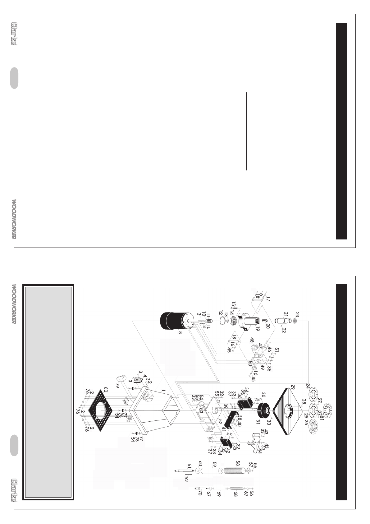
PARTS DIAGRAM (Machine)
SERVICE: [email protected]
PARTS: [email protected]
PARTS & SERVICE TEL: 020 8988 7400
or e-mail as follows:
Page 5
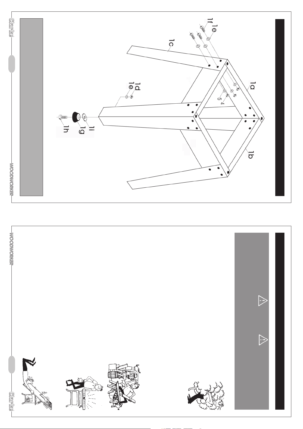
The use of parts other than CLARKE replacement parts may result in safety hazards,
decreased tool performance and may invalidate your warranty.
-11-
IMPORTANT:
PARTS DIAGRAM (Stand)
-4-
11. ALWAYS ensure the switch is off before plugging in to mains. Avoid accidental starting.
13. ALWAYS keep your proper footing and balance at all
times don’t overreach. For best footing, wear rubber
soled footwear. Keep floor clear of oil, scrap wood, etc.
12. ALWAYS concentrate on the job in hand, no matter how trivial it may seem. Be aware
that accidents are caused by carelessness due to
familiarity.
10. ALWAYS handle with extreme care do not carry the tool/machine
by its’ electric cable, or yank the cable to disconnect it from the
power supply.
9. ALWAYS maintain machine in top condition. Keep tools/machines
clean for the best and safest performance. Follow maintenance
instructions.
8. ALWAYS keep children away. All visitors should be kept a
own shadow.
safe distance from the work area, especially whilst operating
the machine.
2. ALWAYS use a face or dust mask if operation is particularly dusty.
4. ALWAYS disconnect the tool/machine from the power supply before servicing and
5. ALWAYS wear safety goggles, manufactured to the latest European Safety Standards.
6. ALWAYS keep work area clean. Cluttered areas and benches invite accidents.
7. ALWAYS ensure that adequate lighting is available. A
that may affect the machines’ operation. Any damage should be properly repaired
or the part replaced. If in doubt, DO NOT use the machine. Consult your local dealer.
when changing accessories.
minimum intensity of 300 lux should be provided. Ensure
that lighting is placed so that you will not be working in your
Everyday eyeglasses do not have impact resistant lenses, they are not safety glasses.
3. ALWAYS check for damage. Before using the machine, any
damaged part, should be checked to ensure that it will operate
properly, and perform its intended function. Check for alignment of
moving parts, breakage of parts, mountings, and any other condition
1. ALWAYS Learn the machines’ applications, limitations and the specific potential
hazards peculiar to it. Read and become familiar with the entire
operating manual.
ignored, personal injury to the operator or damage to property, may result.
As with all machinery, there are certain hazards involved with their operation
and use. Exercising respect and caution will considerably lessen the risk of
personal injury. However, if normal safety precautions are overlooked or
SAFETY PRECAUTIONS
WARNING:
Page 6
-5- -10-
Additionally, please keep these instructions in a safe place for future reference.
8. Sanding of Lead based paint is not recommended, contaminated dust could result
in lead poisoning.
ADDITIONAL PRECAUTIONS FOR VERTICAL SANDER
1. ALWAY S use genuine replacement sanding sleeves.
2. DO NOT use the machine if the electric cable, plug or motor is in poor condition.
3. DO NOT let the ventilation slots in the machine become blocked.
4. Replacement sanding sleeves are available from your CLARKE dealer.
5. Ensure the sanding sleeve is fully secured before use.
6. Switch the machine OFF immediately the task is completed.
7. Never stand on the machine. serious injury could occur if the machine is tipped over.
21 DO NOT use in explosive atmosphere (around paint,
flammable liquids etc). Avoid dangerous environment.
20. NEVER use power tools in damp or wet locations or expose
accessories could be hazardous.
Do not leave the machine until it comes to a complete stop.
the rate for which it was designed.
them to rain. Keep your work area well illuminated.
changing parts or working on the machine.
15. A LWAY S use recommended accessories, the use of improper
16. A LWAY S remove plug from electrical outlet when adjusting,
17. NEVER operate machine while under the influence of drugs, alcohol or any medication.
18. NEVER leave machine running unattended, turn power off.
19. NEVER force the machine, it will do a better and safer job at
14. A LWAY S wear proper apparel. Loose clothing or jewellery may
get caught in moving parts. Wear protective hair covering
to contain long hair.
always close cover to prevent accidental starting.
tends to throw the material away from the sanding sleeve.
required.
It is an EEC requirement that a dust extraction facility be provided on power tools,
however, due to the nature of the tool, some of the dust produced will be forced into the
surrounding atmosphere, and will not be collected.
MAINTENANCE
The sander is provided with a dust extraction facility, where a vacuum extractor may
be connected to the 50mm outlet at the rear of the machine, note however, that this
does not preclude the user from wearing a face mask to prevent the inhalation of dust
particles.
DUST EXTRACTION
Clean the machine regularly using soft brush and clean cloth only.
Always inspect the tool before use, and ensure it is in top condition.
Ensure all air vents are clear.
Check the power cable to ensure it is sound and free from cracks, bare wires etc.
Avoid using solvents when cleaning plastic parts, most plastics are susceptible to damage
from the various types of commercial solvents.
All bearings etc, in this tool are lubricated with a sufficient amount of high grade lubricant
for the tools lifetime under normal operating conditions, therefore no further lubrication is
be worked from right to left, otherwise if fed from the other direction, the rotation force,
3. Once the machine has reached full speed, slowly offer the workpiece to the sanding
NOTE: the sanding sleeve rotates in a clockwise direction, therefore the workpiece should
sleeve.
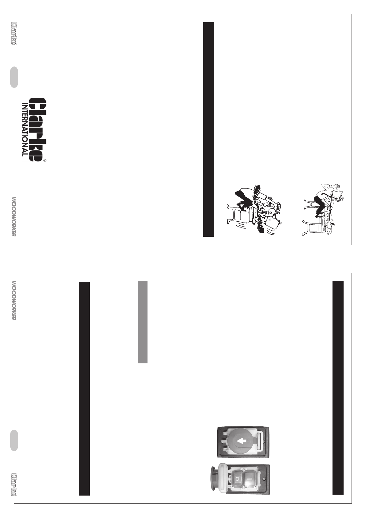
switch OFF normally, press OFF button, (red button ‘O’),
cover will latch down and motor will be switched OFF. To
2. Allow the motor to reach full speed before offering work to the sanding sleeve.
NOTE : in case of emergency, close the switch cover quickly,
again.
Fig. 9
Before starting the machine, ALWAYS inspect for damaged or worn parts etc. Any defects
should be rectified before continuing. Also ensure the machine table is completely clear,
i.e. there are no tools etc left on the machine that could come into contact with the
sanding sleeve when the machine is switched ON, this could cause the tool to fly off, and
possibly lead to personal injury.
The sander is designed for use with wood and plastic materials ONLY. Sanding metal and
abrasive materials could be hazardous.
Before starting work, select the correct size arbor and sanding sleeve for the work to be
carried out, and fit as explained on page 9.
Sanding
1. To switch ON, press the switch cover (see fig. 9) in and
slide in direction of arrow, this will expose the ON/OFF
buttons, Push the ON button, (green button ‘I’). DO
NOT close the cover as this will switch the machine OFF
OPERATION
Page 7
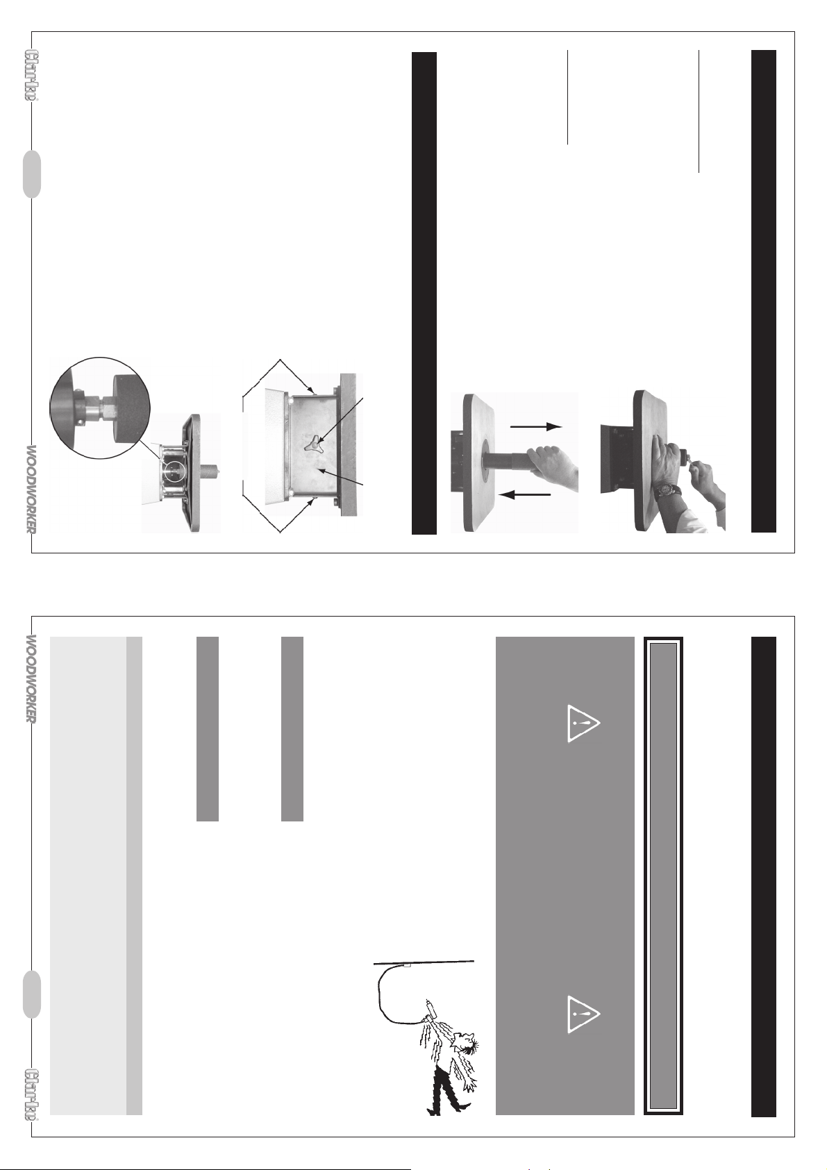
size of the arbor with sanding sleeve fitted.
NOTE: it is important to fit an insert as close as possible to the
4. Select required arbor and fit in reverse order.
NEVER operate the sander with any covers removed.
5. Refit front cover and retain in place with screws
removed earlier.
4. It may be necessary to change the table insert for the
direction and remove, store safely.
chosen arbor, this is done by simply removing two
retaining screws, lift out insert, fit new insert, ensure it is lined up on
locating pin, refit retaining screws.
3. Using two 17mm open ended spanners, one on
the spindle and the other on the arbor base.
Holding the spindle, unscrew the arbor in clockwise
1. Loosen and remove two screws (see Fig. 7).
2. Remove front cover to expose Arbor base and
spindle (see Fig. 8).
before installing onto the arbor.
apply french chalk/talcum powder on the inside of the sleeve
Ensure the machine is switched off and isolated from the power supply by removing the
plug from the 13amp socket, then proceed as follows.
NOTE: If sanding sleeves become difficult to remove or install,
CHANGING ARBORS
2. Grasp and hold the sanding sleeve as above, tighten
the nut in anticlockwise direction. Do Not Overtighten,
tighten sufficiently to hold the sleeve without slipping.
To Fit New Sleeve
1. Slide new sleeve onto arbor, in direction ‘B’ until it is flush
with the top of the rubber cylinder.
surrounding areas.
2. Slide old sanding sleeve off arbor in direction of arrow
Clean sawdust accumulation from arbor and
‘A’ (see Fig. 6).
1. Grasp and hold the sanding sleeve, loosen the nut on
top of the arbor using 14mm spanner in a clockwise
direction (see Fig. 5).
Ensure the machine is switched off and isolated from the power supply by removing the
plug from the 13amp socket, then proceed as follows.
To Remove Old Sleeve
CHANGING SANDING SLEEVES
-9- -6-
WARNING
Fig. 8
Screws
Fig. 7
Handle
Front Cover
Fig. 6
A
Fig. 5
B
230v From 20 to 50m 4mm
2
to the electric cable (i.e. non-rewireable) please note:
The fuse in the plug must be replaced with one of the same rating (5 amps) and this
replacement must be approved to BS1362.
Always use an approved cable extension suitable for the power rating of this tool (see
specifications), the conductor size should also be at least the same size as that on the
machine, or larger. When using a cable reel, always unwind the cable completely.
If a cable extension is needed, it is essential to comply with the following data.
Voltage Extension length Cable section
230v Up to 20m 2.5mm
If in doubt, consult a qualified electrician. Do not attempt any electrical repairs yourself.
Cable Extension
4. Replacement fuse covers can be obtained from your local dealer or most electrical
Fuse Rating
stockists.
2. Never use the plug without the fuse cover fitted.
3. Should you wish to replace a detachable fuse carrier, ensure that the correct
replacement is used (as indicated by marking or colour code).
1. The plug must be thrown away if it is cut from the
electric cable. There is a danger of electric shock if it
is subsequently inserted into a socket outlet.
IMPORTANT:
2
If this appliance is fitted with a plug which is moulded on
• Connect the BLUE coloured cord to the plug terminal marked “N”
• Connect the BROWN coloured cord to the plug terminal marked “L”
• Connect the GREEN/YELLOW coloured cord to the plug terminal marked “E”
This machine must be wired up in accordance with the following colour code:
This product is fitted with a standard 13 amp, 230 volt (50Hz), BS 1363 plug, for connection
to a standard, domestic electrical supply. Should the plug need changing at any time,
ensure that a plug of identical specification is used.
ELECTRICAL CONNECTIONS
WARNING ! THIS APPLIANCE MUST BE EARTHED
GREEN/YELLOW - EARTH
BROWN - LIVE
BLUE - NEUTRAL
Page 8
-7- -8-
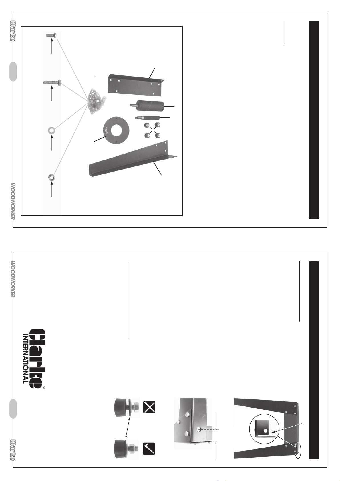
these holes are different distances from the ends, (see Fig. 2 & 3 on page 8).
they can be recognised by the single holes at each end on the top of each cross member,
NOTE: the cross members are not all identical, there are two variations and two of each,
a. Legs ................................................................................................................... 4off
b. Cross members ................................................................................................ 4off
c. Feet ................................................................................................................... 4off
d. ¾” arbor complete with sanding sleeve .................................................... 1off
e. Table inserts ..................................................................................................... 4off
f. 2” arbor complete with sanding sleeve fitted (Fitted in sander) ........... 1off
‘A’ ‘B’ ‘C’ ‘D’
24 off 4 off 28 off 28 off
g. Bag containing fixing nuts, screws and washers ...................................... 1off
1. Sander.
2. Stand (see Fig. 1).
3. Operating Instructions.
Before starting check contents of carton and inform Clarke International of any shortages
immediately.
Check List
ASSEMBLY
b
g
Fig. 1
f
d
c
e
a
Again the legs must be outside of the cross members, and
second cross member must sit on top of the first cross
member fitted, otherwise the holes will not line up correctly.
Once all screws are fitted finger tight, stand the assy on a
flat surface, proceed to tighten all screws, checking as
you do the assy remains square stable.
Once all screws are fully tightened, turn the assy upside
down and fit the rubber feet as follows.
5. Carefully with assistance turn the completed assy onto it’s feet.
Before using the machine, it is necessary to remove all the protective grease from the
table etc using a suitable cleaning/degreasing agent, ALWAYS follow manufacturers
instructions.
4. Using 4 bolts (‘B’), 4 washers (‘C’) and 4 nuts (‘D’), fasten stand to the machine,
one bolt on each corner, Do Not fully tighten until all four bolts are fitted finger
tight.
surface.
tight is adequate.
2. Remove nut and washer.
3. fit one foot assy to each leg, Do Not Overtighten.
Fit stand assy to sanding machine.
1. Remove the installed arbor ref instructions on page 9.
2. Carefully turn the sander upside down on a clean flat
3. Position the stand assy upside down onto the machine
base.
1. check and adjust if necessary all four foot assy’s
are set as shown in Fig. 4.
Ensure the nut washer is wound right down, finger
(see Fig. 2).
NOTE: legs must be fitted on the outside of the cross member
2. Fit other cross members with single holes 29mm from
(‘A’), 6 off washers (‘C’) and 6 off nuts (‘D’), per assy,
ends to leg assemblies (see Fig. 3) using, 6 off screws
(‘A’), 6 off washers (‘C’) and 6 off nuts (‘D’) per cross
member, finger tight only.
finger tight at this stage only.
Assemble stand as follows.
1. Fit two legs to each of the cross members with single
holes 12mm from ends (see Fig. 2), using 6 off screws
ASSEMBLY Cont
Fig. 4
Fig. 3
12mm approx
Fig. 2
29mm approx
 Loading...