

Page 1
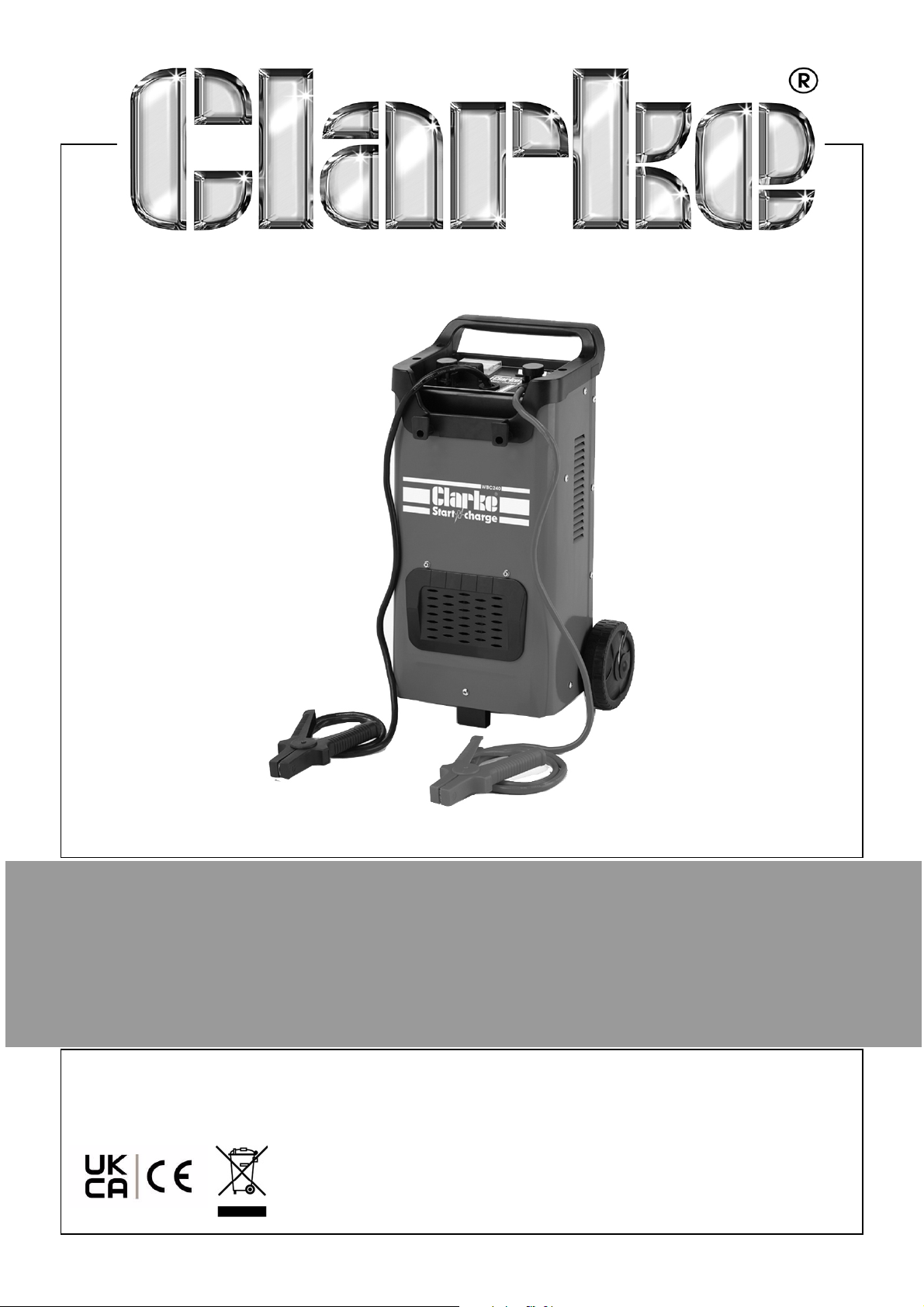
BATTERY CHARGER-STARTER
MODEL NO: WBC180
PART NO: 6261500
OPERATION & MAINTENANCE
INSTRUCTIONS
ORIGINAL INSTRUCTIONS
DL0621 - ISS 3
Page 2

INTRODUCTION
Thank you for purchasing this CLARKE Battery Charger.
Please read this manual thoroughly, before attempting to operate, and
carefully follow all instructions given.
It is vitally important that ALL precautions are taken, as specified, which will not
only provide protection for yourself and that of others around you, but will also
ensure that the Battery Charger will give you long and satisfactory service.
GUARANTEE
This CLARKE product is guaranteed against faulty manufacture for a period of
12 months from the date of purchase. Please keep your receipt as proof of
purchase.
This guarantee is invalid if the product is found to have been abused or
tampered with in any way, or not used for the purpose for which it was
intended.
Faulty goods should be returned to their place of purchase, no product can
be returned to us without prior permission.
This guarantee does not effect your statutory rights.
ENVIRONMENTAL RECYCLING POLICY
Through purchase of this product, the customer is taking on the
obligation to deal with the WEEE in accordance with the WEEE
regulations in relation to the treatment, recycling & recovery and
environmentally sound disposal of the WEEE.
In effect, this means that this product must not be disposed of with general
household waste. It must be disposed of according to the laws governing
Waste Electrical and Electronic Equipment (WEEE) at a recognised disposal
facility.
If disposing of this product or any damaged components, do not dispose of
with general waste. This product contains valuable raw materials. Metal
products should be taken to your local civic amenity site for recycling of metal
products.
2
Parts & Service: 020 8988 7400 / E-mail: [email protected] or [email protected]
Page 3
SPECIFICATIONS
Model Number WBC180
Battery Voltages 12 & 24V
Suitable Battery Types Lead Acid inc GEL, WET, AGM
IP Rating IP20
Maximum Battery Size 500 Ah
Operating Temperature Range 0 to 40°C
Dimensions (D x W x H) 274 x 370 x 590 mm
Weight 14.1 kg
Estimated Engine Capacity up to 1.6 L
Rated DC output voltage 12 & 24V
Rated DC output current 35A
Input Voltage @ 50Hz 230 V Ac
Short Circuit Protection 110A
Ammeter Range 0-60A
Starting Duty Cycle 3 sec On / 120 sec Off
Max Output Current (Starting @ 12V/24V) 220/180 A @ max duty cycle
Max Output Current (Charging @ 12V/24V) 35/35 A
Rated Input Power (Charging mode) 1.24 kW
Max Input current
Starting @ 12V/24V 12V/19A and 24V/28A
Charging @ 12V/24V 12V/3.8A and 24V/5.5A
Open Circuit Voltage (Output)
Starting @ 12V/24V 14.79 / 29.43
Boost @ 12V/24V 12.35 / 24.73
Charging 1@ 12V/24V 11.12 / 22.26
Charging 2 @ 12V/24V 11.71 / 23.46
3
Parts & Service: 020 8988 7400 / E-mail: [email protected] or [email protected]
Page 4
SAFETY PRECAUTIONS
WARNING: HIGHLY INFLAMMABLE HYDROGEN GAS IS RELEASED IN THE
PROCESS OF BATTERY CHARGING. ALWAYS REMEMBER TO SWITCH OFF
THE CHARGER/STARTER FIRST TO AVOID SPARKING.
PLEASE READ BEFORE USING THIS UNIT
1. Battery acid is very corrosive. If spilled, clean the area immediately and
wash with water. If battery acid comes into contact with the eyes, get
medical help immediately.
2. Do not expose this charger/starter to rain.
3. Never touch the negative and positive leads together while the unit is
switched on.
4. Never attempt any electrical or mechanical repair yourself other than
replacement of fuses. If you have a problem with your battery charger
contact your local stockist for service information.
WARNING: CERTAIN TYPES OF SEALED OR MAINTENANCE-FREE BATTERIES
NEED EXTRA CARE WHEN CHARGING. PLEASE CONSULT THE BATTERY
MANUFACTURERS INSTRUCTIONS BEFORE USING THIS CHARGER/STARTER.
WARNING: TOXIC FUMES MAY BE RELEASED DURING BATTERY
CHARGING. ONLY USE THIS CHARGER/STARTER IN A WELL VENTILATED
AREA.
5. Before charging, make sure that the battery terminals are clean, and the
cells are filled to the correct level by adding distilled water where
necessary.
6. This charger/starter is not intended for use by persons with reduced
physical, sensory or mental capabilities, or lack of experience and
knowledge, unless they have been given supervision or instruction
concerning use of the charger/starter by a person responsible for their
safety. Keep children well away from the charger/starter.
7. After charging, secure the vehicle battery leads to the correct terminals
which should be clean, and lightly smeared with petroleum jelly to prevent
corrosion. Finally, re-check the battery electrolyte level.
8. Do not use this charger/starter unless you are aware of vehicle electrical
systems and battery charging techniques.
4
Parts & Service: 020 8988 7400 / E-mail: [email protected] or [email protected]
Page 5
9. Always consult the vehicle manufacturers instructions for disconnecting /
charging the vehicle battery.
CAUTION: SOME VEHICLE ELECTRONIC EQUIPMENT CAN BE DAMAGED
BY BOOST CHARGING OR USE OF THE START FACILITY. CHECK YOUR
VEHICLE HANDBOOK BEFORE USING YOUR STARTER/CHARGER. IF IN
DOUBT CONSULT THE VEHICLE MANUFACTURER.
5
Parts & Service: 020 8988 7400 / E-mail: [email protected] or [email protected]
Page 6
ELECTRICAL CONNECTION
WARNING! READ THESE ELECTRICAL SAFETY INSTRUCTIONS
THOROUGHLY BEFORE CONNECTING THE PRODUCT TO THE
MAINS SUPPLY.
WARNING! THIS APPLIANCE MUST BE EARTHED
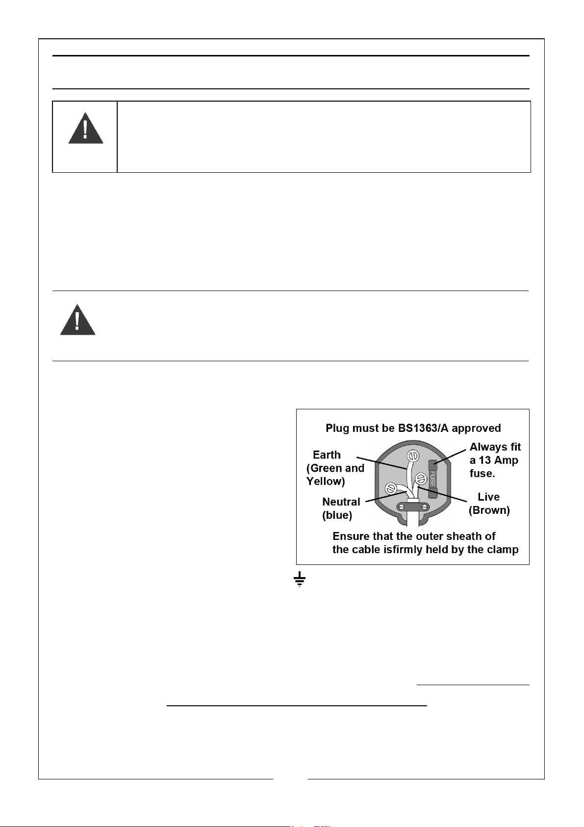
Connect the mains lead to a standard, 230 Volt (50Hz) electrical supply
through an approved 13 amp BS1363 plug, or a suitably fused isolator switch,
If the plug has to be changed because it is not suitable for your socket or
because of damage, it must be removed and a replacement fitted, following
the wiring instructions shown below. The old plug must be discarded safely as
insertion into a power socket could cause an electrical hazard.
WARNING: THE WIRES IN THE POWER CABLE OF THIS PRODUCT ARE
COLOURED IN ACCORDANCE WITH THE FOLLOWING CODE:
BLUE = NEUTRAL BROWN = LIVE YELLOW AND GREEN = EARTH.
If the colours of the wires in the power cable do not agree with the markings
on the plug:
• The BLUE wire must be
connected to the terminal
which is marked “N” or coloured
black.
• The BROWN wire must be
connected to the terminal
which is marked “L” or coloured
red.
• The YELLOW AND GREEN wire
must be connected to the
terminal which is marked “E” or or coloured green.
We strongly recommend that this machine is connected to the mains supply
via a Residual Current Device (RCD).
If you are not sure, consult a qualified electrician. DO NOT try to carry out any
repairs yourself.
The maximum rated supply current for this unit is 28 amps with a
duty cycle of 3 secs on/120 secs off
6
Parts & Service: 020 8988 7400 / E-mail: [email protected] or [email protected]
Page 7
OVERVIEW
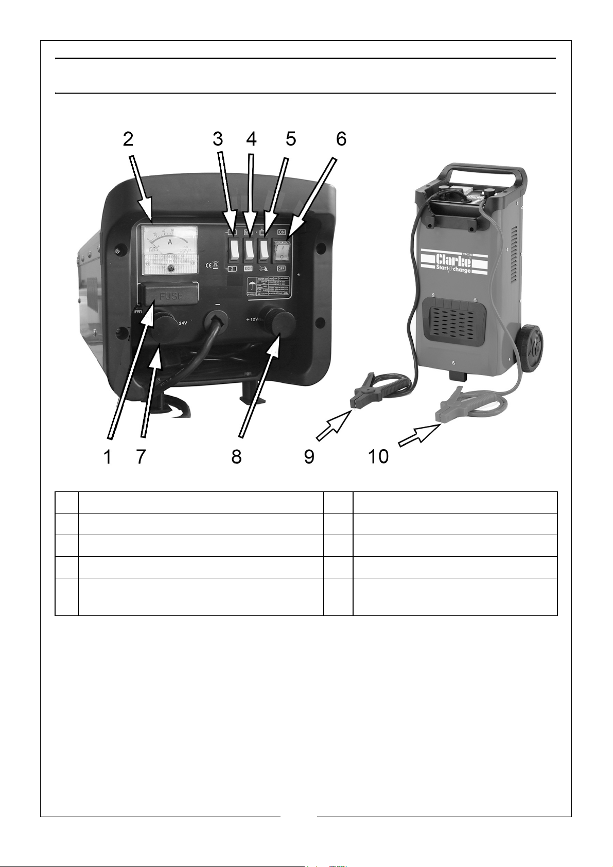
1 Fuse Holder 6 Power On/Off Switch
2 Charging condition meter (Amps) 7 Positive Terminal +24V
3 High/Low Charging Selector 8 Positive Terminal +12V
4 Min/Boost Charge Charging Selector 9 Negative (BLACK) lead
5 Battery Charge/Jump Start Mode
Selector switch
The WBC180 model is provided with a pair of leads complete with clamps for
connection to a battery via the appropriate outlet connections - 12V and 24V,
as shown.
Three selector switches provide for different functions as shown above. The
main fuse is mounted on the front panel, as shown and both models
incorporate a thermal overload cut-out.
10 Positive (RED) lead
7
Parts & Service: 020 8988 7400 / E-mail: [email protected] or [email protected]
Page 8
ASSEMBLY
ASSEMBLY
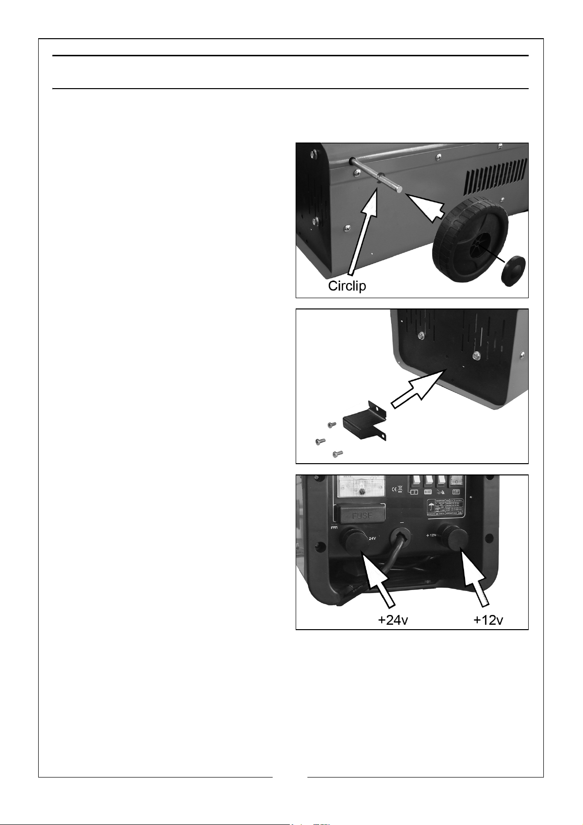
1. Pass the axle through the holes in
the body of the machine and fit
circlips to the axle at the position
shown.
2. Slide the wheels onto each end of
the axle and secure with further
circlips outside each wheel.
3. Press-fit the caps to the wheels.
4. Install the foot to the base of the
machine using the three screws as
shown.
5. Fit the positive battery lead to the
terminal of your choice (12/24V)
to match the voltage of the
battery.
8
Parts & Service: 020 8988 7400 / E-mail: [email protected] or [email protected]
Page 9

GENERAL PREPARATION
CHARGER LOCATION
1. Place the charger as far away from the car battery as possible.
2. Do not position the charger above the battery during the charging
procedure. Gases from the battery will cause corrosion and damage the
charger.
3. Do not let battery acid drip on anything when reading specific gravity or
when topping up the battery.
4. Do not operate the charger in an enclosed space, such as inside the
vehicle. Never cover the battery charger.
5. Do not stand the battery on top of the charger.
6. Always stand the battery charger on a firm, level floor.
7. During charging, make sure that the area around the battery has good
ventilation.
CONNECTING THE BATTERY
1. Before charging, disconnect the battery from the vehicle.
2. Always remove the grounded (earth) terminal from the battery first. Make
sure that all electrical accessories in the vehicle are switched off to prevent
sparking.
3. Clean the battery terminals. Be careful to prevent battery electrolyte from
coming in contact with your eyes.
4. Except for sealed units, add distilled water to each cell until the battery
acid reaches the level specified by the battery manufacturer.
• This helps drive unwanted gas from the cell. Do not overfill. For a battery
without cell caps, consult the manufacturer's instructions.
5. Follow all the battery manufacturer's specified precautions: for example,
removing or not removing cell caps while being charged, and
recommended rates of charge.
6. Refer to the vehicle manual to find the voltage of the battery and make
sure that the charging cable is connected to the correct terminal (either
12/24V).
7. This charger has an adjustable charge rate and the battery should be
charged initially at the lowest rate.
9
Parts & Service: 020 8988 7400 / E-mail: [email protected] or [email protected]
Page 10
CONNECTING TO A BATTERY
WARNING: A SPARK NEAR THE BATTERY MAY CAUSE BATTERY EXPLOSION.
TO REDUCE THE RISK OF A SPARK NEAR THE BATTERY:
• Turn off the charger before you connect/disconnect the DC
output connectors.
• Do not let the connectors touch each other.
• Attach the connectors to battery terminals and make sure that
you get a good connection.
BATTERY CHARGING
CHARGING A BATTERY INSTALLED IN THE VEHICLE
1. Position the leads carefully to reduce the risk of damage from any sharp
edges.
2. Check the polarity of the battery posts.
3. Consult the vehicle manual to confirm if the vehicle has a Negative or
Positive earth.
• For negative earth vehicles, connect the POSITIVE (RED) lead from the
battery charger to the POSITIVE terminal on the battery. Connect the
NEGATIVE (BLACK) lead to the vehicle frame or engine block away from
the battery.
• For positive earth vehicles, connect the NEGATIVE (BLACK) lead from the
battery charger to the NEGATIVE terminal on the battery. Connect the
POSITIVE (RED) lead to the vehicle frame or engine block away from the
battery.
• Do not connect the lead to ancilliary engine components.
4. Where appropriate, we recommend that the non-earthed lead on the
battery is disconnected prior to charging.
• This will reduce the risk of damage to the vehicle’s electronic
equipment.
5. When charging is completed, switch off the charger/starter and unplug it.
Remove the lead from the vehicle earth point, and then remove the lead
from the battery.
CHARGING A BATTERY REMOVED FROM THE VEHICLE
1. Make sure that you know the polarity of the battery posts.
10
Parts & Service: 020 8988 7400 / E-mail: [email protected] or [email protected]
Page 11
2. Connect the POSITIVE (RED) lead to the POSITIVE post on the battery.
3. Connect the NEGATIVE (BLACK) lead at arms length to the NEGATIVE post
on the battery.
4. When you disconnect the charger from the battery, always do it in the
opposite order to the sequence of connection and remove the first
connection at arms length from the battery.
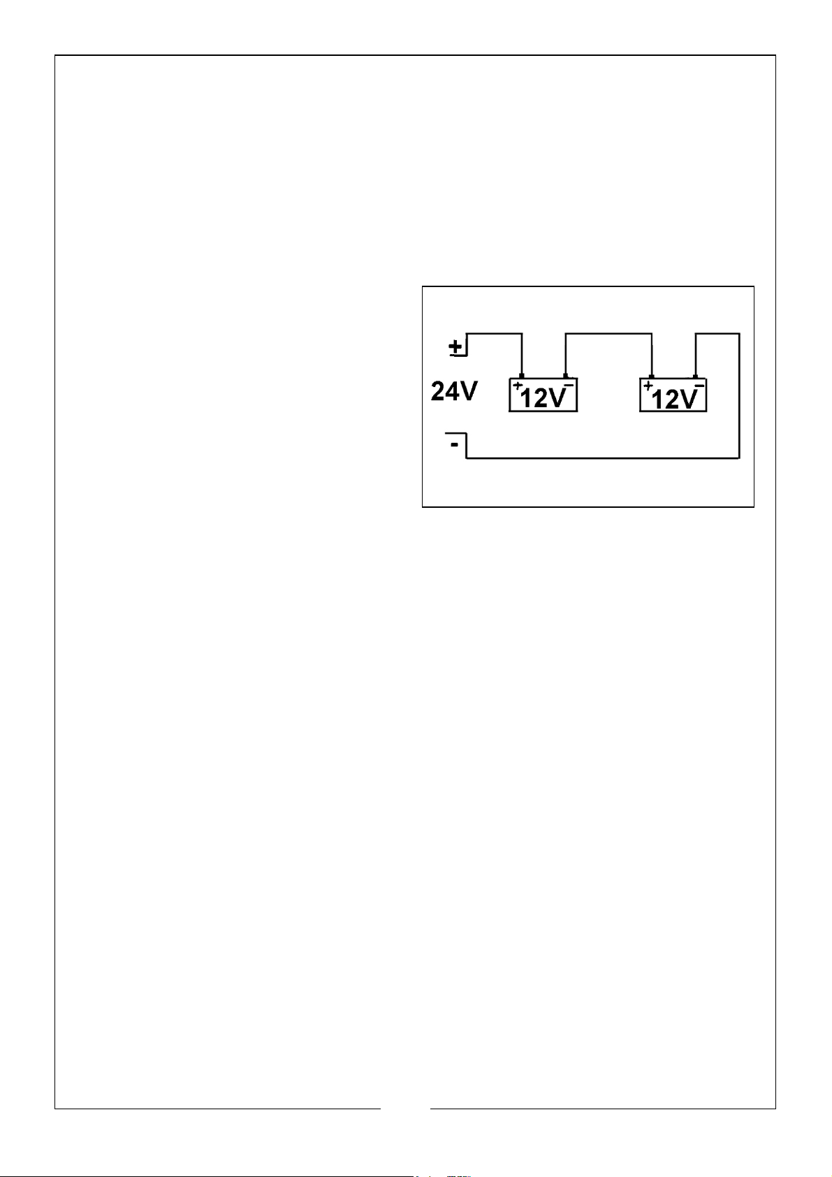
CHARGING MORE THAN ONE BATTERY
1. Simultaneous multiple charging
should be carried out in series,
since this enables monitoring of
the current circulating in each
battery.
2. If two batteries with rated
voltages of 12V are connected in
series, set up the charger using
the positive cable connected to
the 24V terminal.
11
Parts & Service: 020 8988 7400 / E-mail: [email protected] or [email protected]
Page 12
OPERATION OF THE CHARGER
TO CHARGE THE BATTERY
1. Connect the charger to the battery.
2. Connect the charger to the mains supply and switch on.
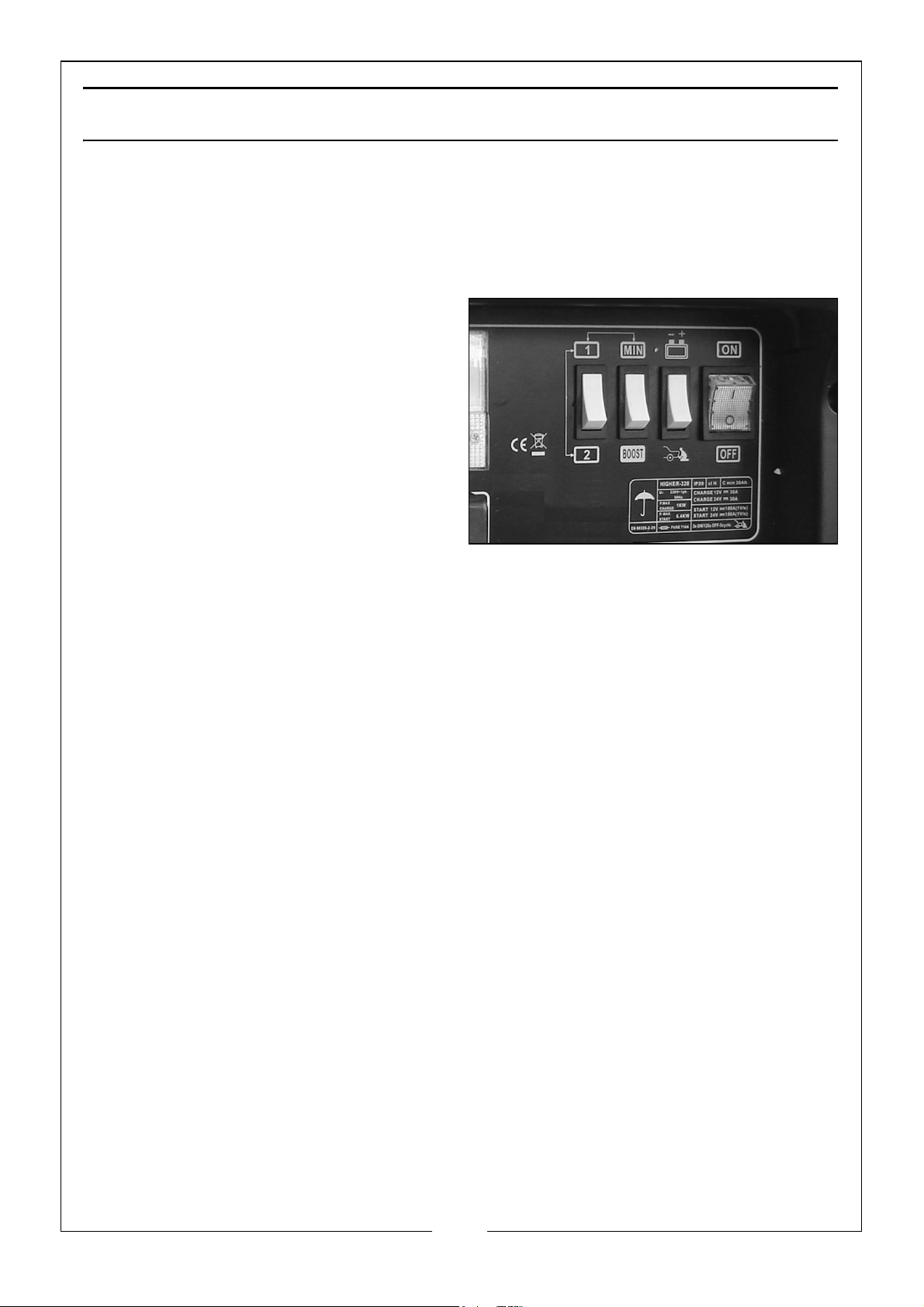
3. Set the mode switch to the
CHARGE function indicated by
the battery symbol.
4. Set the other selector switches to:
• Low charging rate:- MIN and 1.
• Medium charging rate:- MIN
and 2.
• High charging rate:- BOOST.
(this over-rides the 1/2 switch)
5. Check the current delivery by reading the ammeter on the front of the
battery charger.
• During charging, the ammeter on the charger will indicate the current
delivered to the battery. During the charge, the readout will decrease
slowly to the lowest value according to the capacity and condition of
the battery. When the reading becomes very low, no further charging is
necessary.
• Charge a sealed battery very slowly at the lowest settings of MIN/1,
monitoring the voltage across the battery terminals using a volt meter.
• When the battery terminal voltage reaches 14.4V for 12V batteries, stop
charging.
WHEN CHARGING IS COMPLETE
1. When charging is complete the ammeter reading should be close to “0”
and the electrolyte in the battery may begin to gas. Stop charging to
protect the battery plates from damage.
2. Switch off the charger and disconnect the plug from the power socket.
• Remove the leads from the battery as described in the previous
sections.
• Return the battery to the vehicle. Secure and re-connect, ensuring all
tools are removed from the battery area.
12
Parts & Service: 020 8988 7400 / E-mail: [email protected] or [email protected]
Page 13
PROCEDURE FOR ENGINE STARTING
CAUTION: WE RECOMMEND THAT BEFORE ATTEMPTING TO BOOST START,
YOU CHARGE THE BATTERY FOR 10-15 MINUTES. THIS WILL IMPROVE THE
CHANCE OF A FIRST TIME START, PARTICULARLY WITH LARGER ENGINES.
CAUTION: WHEN THE BATTERY IS COMPLETELY FLAT, YOU MUST CHARGE
THE BATTERY BEFORE ATTEMPTING TO START THE ENGINE, OTHERWISE
YOU MAY CAUSE DAMAGE TO THE VEHICLE ELECTRONIC SYSTEM.
1. Check that mains supply switch is OFF.
2. Set the CHARGE/START switch in the START position.
3. Set the MIN/BOOST switch in the MIN position.
4. Connect the cables to the vehicle battery as for charging.
5. Set the ON/OFF switch to ON.
6. Turn the key in the vehicles ignition to ‘start’, and crank the engine for a
maximum of 3 seconds. If the vehicle does not start, wait 2 minutes before
trying again for a maximum of 5 cycles.
WARNING: IF THE ENGINE WILL NOT START, DO NOT CONTINUE AS THE
VEHICLE BATTERY AND ELECTRICAL CIRCUITS MAY BE DAMAGED AND
THE FUSE IN THE CHARGER WILL BLOW. DISCONNECT THE CHARGER AND
INVESTIGATE FOR VEHICLE FAULTS. THE DUTY CYCLE FOR STARTING (3
SECS ON/2 MINUTES OFF MUST NOT BE EXCEEDED.
7. When the engine starts, switch the charger off immediately. Unplug from
the mains power and disconnect the starter/charger from the battery.
THERMAL CUTOUT
NOTE: If the battery charger is overloaded at any time, a thermal cut out will
automatically come into operation, rendering it inoperative. Allow
approximately 5-10 minutes before using the unit again.
13
Parts & Service: 020 8988 7400 / E-mail: [email protected] or [email protected]
Page 14
FUSES
1. The starter/charger is equipped with a safety fuse which will protect the
unit under the following circumstances:
• Overload - too high a current to the battery.
• Short Circuit - clamps touch or cross connection to battery.
• Prolonged starting attempts.
REPLACING THE FUSE
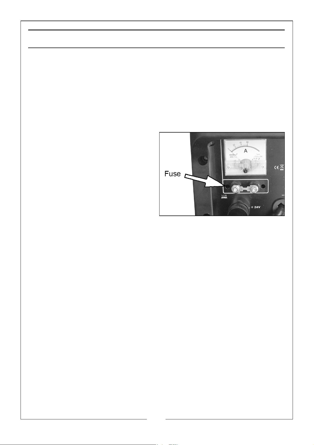
The fuse fitted is rated at 110A and is
fitted behind the clip-on cover for
easy replacement.
1. Switch the unit off and disconnect
from the mains.
2. Allow the unit to cool down and
establish the reason for the failure
and correct.
3. Pull off the fuse cover before
unscrewing the nuts to remove
the fuse. Replace only with an identical fuse and with the same rating, as
supplied with your starter/charger.
• Replacements are available from your Clarke dealer.
14
Parts & Service: 020 8988 7400 / E-mail: [email protected] or [email protected]
Page 15
MAINTANENCE
This charger requires minimal maintenance. As with any appliance or tool, a
few common sense rules will prolong the life of the battery charger.
WARNING: ALWAYS BE SURE THE CHARGER IS UNPLUGGED BEFORE
PERFORMING ANY MAINTENANCE OR CLEANING.
1. Clean the case and leads with a moist cloth.
2. Clean corrosion from the clamps with a solution of water and baking soda.
3. Examine the leads at regular intervals for damage and have them
replaced if necessary.
WARNING: ALL OTHER SERVICING/REPAIRS SHOULD BE DONE BY
QUALIFIED SERVICE PERSONNEL ONLY.
STORAGE
1. Wind up the connecting leads and power cable when not in use and store
in the compartment when not being used.
2. Store in a clean, dry area.
15
Parts & Service: 020 8988 7400 / E-mail: [email protected] or [email protected]
Page 16
Page 17
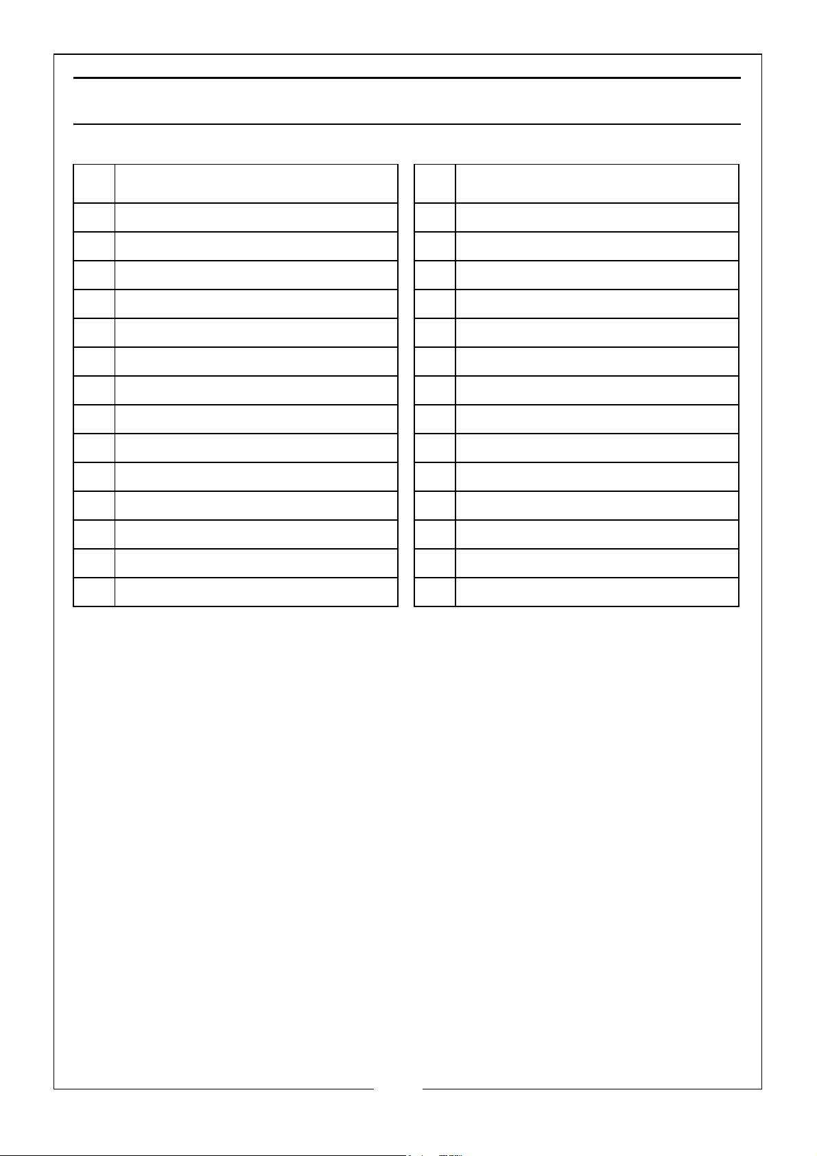
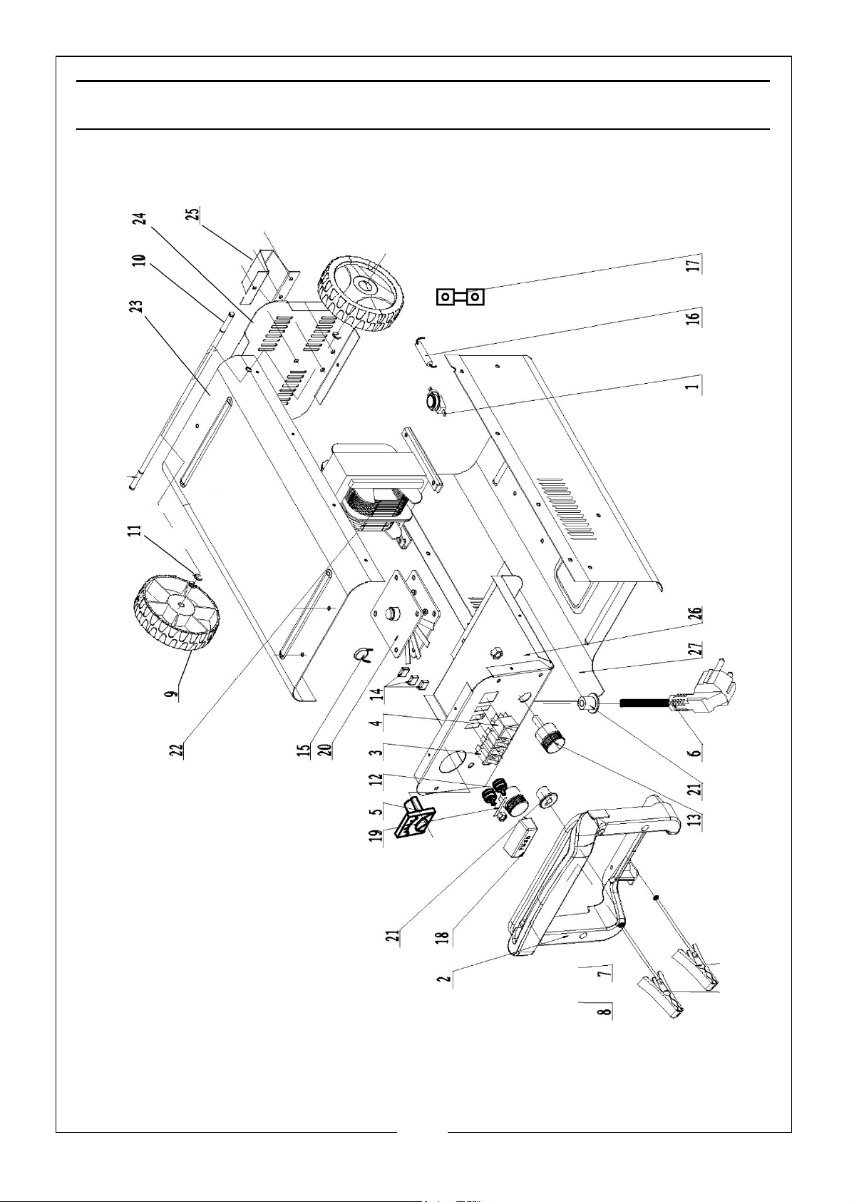
PARTS LIST
NO DESCRIPTION NO DESCRIPTION
1 Thermostat 15 Varistor
2 Front Handle 16 Resistor
3 Selector Switch 17 Diverter
4 On/Off Switch 18 Fuse Cover
5 Ammeter 19 Fuse (110A)
6 Power Cable & Plug 20 Rectifier Bridge
7 Earth Clamp (black) 21 Cable Gland
8 Live Clamp (Red) 22 Transformer
9 Wheel 23 Back Panel
10 Axle 24 Bottom Panel
11 Circlip 25 Foot
12 Fuse Post 26 Top Panel
13 Connection Post 27 Front Panel
14 Capacitor
17
Parts & Service: 020 8988 7400 / E-mail: [email protected] or [email protected]
Page 18

TROUBLESHOOTING
Problem Cause Solution
Battery does not
charge
Lack of AC input power. Make sure that the charger
is plugged into a suitable
power outlet and the ON/
OFF switch lights up.
Faulty connections to
battery terminals.
Wrong charge voltage
selection.
Battery voltage too low. Ensure enough charging
Charging a very cold
battery.
Unplug the charger and
check the battery
connection; ensure that
there is a good connection
at the battery terminal/post
and/or vehicle chassis.
Check that the correct
charge voltage was
selected for the battery
being charged.
time was allowed to charge
battery.
If the battery being
charged is extremely cold
(below freezing), it will not
accept a high rate of
charge, so the initial
charger rate will be slow.
The rate of charger will
increase as the battery
warms.
Never attempt to charge a
frozen battery.
18
Parts & Service: 020 8988 7400 / E-mail: [email protected] or [email protected]
Page 19
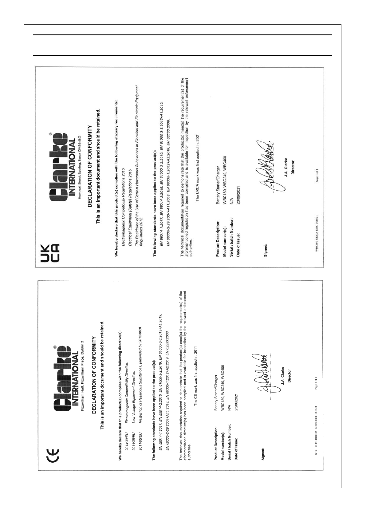
DECLARATION OF CONFORMITY
19
Parts & Service: 020 8988 7400 / E-mail: [email protected] or [email protected]
Page 20

 Loading...