

Page 1
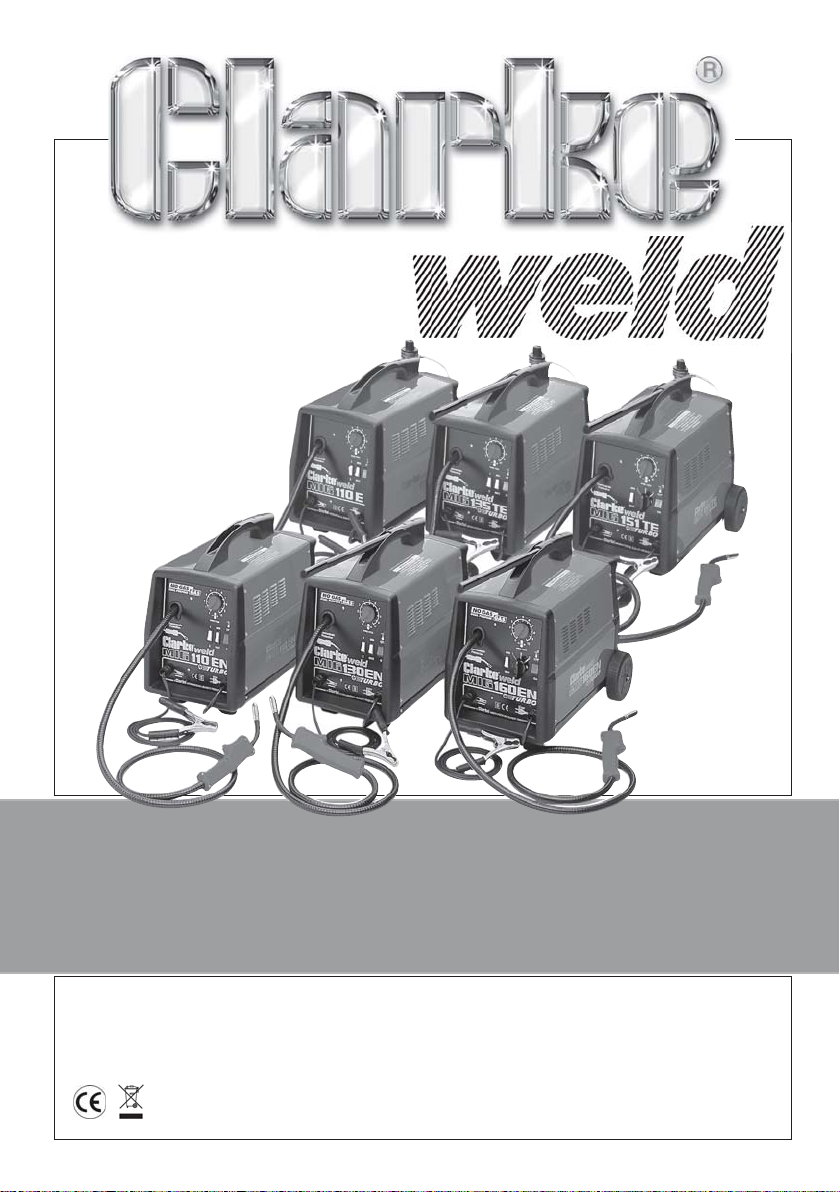
MIG WELDERS
MIG WELDERS
MIG110E - MIG135TE - MIG151TE
MIG110EN - MIG130EN - MIG160EN
OPERATING & MAINTENANCE
INSTRUCTIONS
0719
Page 2

CONTENTS PAGE
Guarantee .............................................................................................. 3
Enviromental Recycling Policy ............................................................. 3
Parts & Service Contacts ....................................................................... 3
Electromagnetic Interference (EMC) .................................................. 4
Safety Precautions ................................................................................. 6
Additional Safety Precautions for MIG Welding ............................... 11
Principles of Operation........................................................................ 13
Electrical Connections ........................................................................ 14
Unpacking and Parts Identification ................................................... 15
Assembly ....................... Loose Components.................................... 15
Welding Shield ........................................... 16
Installing the Welding Wire ....................... 16
Connecting the Gas Supply ..................... 18
Preparation for Use ....... Electrical Connections .............................. 19
Welding Gas Settings ................................. 20
Setting the Controls .................................... 20
Welding Wire Preparation ......................... 21
Attaching the Earth Clamp ....................... 21
MIG Welding Operation ...................................................................... 22
Welding Tips.......................................................................................... 22
Maintenance ........................................................................................ 23
Control Settings Reference Tables ............................................. 24 - 25
Welder Specifications.......................................................................... 26
Wiring Diagrams ........................................................................... 27 - 29
Parts Lists and Diagrams ............................................................. 30 - 41
Troubleshooting.................................................................................... 42
Accessories .......................................................................................... 43
Parts & Service Contacts ..................................................................... 43
2
Page 3
Thank you for purchasing this CLARKE MIG Welder.
The ‘EN’ versions are designed to operate with or without gas....so-called GAS/
NO-GAS welders. The ‘E’ and ‘TE’ versions are designed to operate using a gas
cylinder with plain metal welding wire ONLY. This is explained in greater detail
within the manual.
Before attempting to operate the machine, it is essential that you read this manual
thoroughly and carefully follow all instructions given. In doing so you will ensure
the safety of yourself and that of others around you, and you can also look forward
to the welder giving you long and satisfactory service.
GUARANTEE
This CLARKE product is guaranteed against faulty manufacture for a period of 12
months from the date of purchase. Please keep your receipt as proof of purchase.
This guarantee is invalid if the product is found to have been abused or tampered
with in any way, or not used for the purpose for which it was intended.
Faulty goods should be returned to their place of purchase, no product can be
returned to us without prior permission.
This guarantee does not effect your statutory rights.
ENVIROMENTAL RECYCLING POLICY
Through purchase of this product, the customer is taking on the
obligation to deal with the WEEE in accordance with the WEEE
regulations in relation to the treatment, recycling & recovery and
environmentally sound disposal of the WEEE.
In effect, this means that this product must not be disposed of with general
household waste. It must be disposed of according to the laws governing
Waste Electrical and Electronic Equipment (WEEE) at a recognised disposal
facility.
PARTS AND SERVICE CONTACTS
For Spare Parts and Service, please contact your nearest dealer,
or CLARKE International, on one of the following numbers.
PARTS & SERVICE TEL: 020 8988 7400
PARTS & SERVICE FAX: 020 8558 3622
or e-mail as follows:
PARTS: [email protected]
SERVICE: [email protected]
3
Page 4
ELECTROMAGNETIC INTERFERENCE (EMC)
Whilst this unit complies with EMC regulations, the user is responsible for installing
and using the welding equipment according to the manufacturers instructions. If
electromagnetic disturbances are detected then it shall be the responsibility of
the user of the welding equipment to resolve the situation. In some cases this
remedial action may be as simple as earthing the welding circuit, see ‘Note’. In
other cases it could involve constructing an electromagnetic screen enclosing
the power source and the work complete with associated input filters. In all cases
electromagnetic disturbances must be reduced to the point where they are no
longer troublesome.
Note - The welding circuit may or may not be earthed for safety reasons. Changing
the earthing arrangements should only be authorised by a person who is
competent to assess whether the changes will increase the risk of injury, e.g. by
allowing parallel welding current return paths which may damage the earth circuits
of other equipment.
1.ASSESSMENT OF AREA
Before installing welding equipment the user shall make an assessment of potential
electromagnetic problems in the surrounding area. Avoid using your inverter in
the vicinity of:
a) other supply cables, control cables, signalling and telephone cables;
above, below and adjacent to the welding equipment;
b) radio and television transmitters and receivers;
c) computer and other control equipment;
d) safety critical equipment, e.g. guarding of industrial equipment;
e) pacemakers and hearing aids etc.;
f) equipment used for calibration or measurement;
g) other equipment in the environment. The user shall ensure that other
equipment being used in the environment is compatible. This may
require additional protection measures;
It may be possible to avoid the above by changing the time of day that welding
or other activities are to be carried out.
The size of the surrounding area to be considered will depend on the structure of
the building and other activities that are taking place. The surrounding area may
extend beyond the boundaries of the premises.
2. METHODS OF REDUCING EMISSIONS
2.1 Mains supply
Welding equipment should be connected to the mains supply according to the
manufacturers recommendations. If interference occurs, it may be necessary to
4
Page 5
take additional precautions such as filtering of the mains supply. Consideration
should be given to shielding the supply cable of permanently installed welding
equipment, in metallic conduit or equivalent. Shielding should be electrically
continuous throughout its length. The shielding should be connected to the welding
power source so that good electrical contact is maintained between the conduit
and the welding power source enclosure.
2.2 Maintenance of the welding equipment
The welding equipment should be routinely maintained according to the
manufacturers recommendations. All access and service doors and covers should
be closed and properly fastened when the welding equipment is in operation.
The welding equipment should not be modified in any way except for those
changes and adjustments covered in the manufacturers instructions. In particular,
the spark gaps of arc striking and stabilizing devices should be adjusted and
maintained according to the manufacturers recommendations.
2.3 Welding cables
The welding cables should be kept as short as possible and should be positioned
close together, running at or close to the floor level.
2.4 Equipotential bonding
Bonding of all metallic components in the welding installation and adjacent to it
should be considered. However, metallic components bonded to the work piece
will increase the risk that the operator could receive a shock by touching these
metallic components and the electrodes at the same time. The operator should
be insulated from all such bonded metallic components.
2.5 Earthing of the workpiece
Where the workpiece is not bonded to earth for electrical safety, nor connected
to earth because of its size and position, e.g. ships hull or building steelwork, a
connection bonding the workpiece to earth may reduce emissions in some, but
not all instances.
Care should be taken to prevent the earthing of the workpiece increasing the risk
of injury to users, or damage to other electrical equipment.
Where necessary, the connection of the workpiece to earth should be made by
a direct connection to the workpiece, but in some countries where direct
connection is not permitted, the bonding should be achieved by suitable
capacitance, selected according to national regulations.
2.6 Screening and shielding
Selective screening and shielding of other cables and equipment in the surrounding
area may alleviate problems of interference. Screening of the entire welding
installation may be considered for special applications.
5
Page 6
SAFETY PRECAUTIONS FOR ALL TYPES OF WELDING
1. WARNING:
As with all machinery, there are certain hazards involved with their operation
and use. Exercising respect and caution will considerably lessen the risk of
personal injury. However, if normal safety precautions are overlooked, or
ignored, personal injury to the operator may result.
FAILURE TO FOLLOW THESE RULES MAY RESULT IN SERIOUS PERSONAL INJURY
2. GENERAL PRECAUTIONS
A) Burn prevention
Wear protective clothing - gauntlet gloves designed for use in welding, apron, and
protective shoes. Button shirt collar and pocket flaps, and wear cuffless trousers to
avoid entry of sparks and slag. Wear helmet with safety goggles or glasses with side
shields underneath, appropriate filter lenses or plates (protected by clear cover
glass). This is a MUST for welding or cutting, (and chipping) to protect the eyes from
radiant energy and spatter. Replace cover glass when broken, pitted, or spattered.
Avoid oily greasy clothing. A spark may ignite them. Hot metal such as electrode
stubs and workpieces should never be handled without gloves. First aid facilities
and a qualified first aid person should be available unless medical facilities are close
by for immediate treatment of flash burns of the eyes and skin burns. Ear plugs
should be worn when working overhead or in a confined space. A hard hat should
be worn when others work overhead. Flammable hair preparations should not be
used by persons intending to weld or cut.
B) Toxic fume prevention
Severe discomfort, illness or death can result from fumes, vapours, heat, or oxygen
enrichment or depletion that welding (or cutting) may produce. Prevent them
with adequate ventilation. NEVER ventilate with oxygen. Lead-, cadmium-, zinc-,
mercury- and beryllium-, bearing materials, when welded (or cut) may produce
harmful concentrations of toxic fumes. Adequate local exhaust ventilation must
be used, or each person in the area as well as the operator must wear an airsupplied respirator. For beryllium, both must be used. Metals coated with or
containing materials that emit toxic fumes should not be heated unless coating is
removed from the work surface, the area is well ventilated, or the operator wears
an air-supplied respirator. Work in a confined space only while it is being ventilated
and, if necessary, while wearing an air-supplied respirator. Vapours from chlorinated
solvents can be decomposed by the heat of the arc (or flame) to form PHOSGENE,
a highly toxic gas, and other lung and eye irritating products. The ultraviolet
(radiant) energy of the arc can also decompose trichloroethylene and
perchloroethylene vapours to form phosgene. DO NOT WELD or cut where solvent
vapours can be drawn into the welding or cutting atmosphere or where the radiant
energy can penetrate to atmospheres containing even minute amounts of
trichloroethylene or perchloroethylene.
6
Page 7

C) Fire and explosion prevention
Causes of fire and explosion are:
1) combustibles reached by the arc, flame, flying sparks, hot slag or heated
material;
2) misuse of compressed gases and cylinders;
3) short circuits.
BE AWARE THAT flying sparks or falling slag can pass through cracks, along pipes,
through windows or doors, and through wall or floor openings, out of sight of the
goggled operator. Sparks and slag can fly 10M.
To prevent fires and explosion: keep equipment clean and operable, free of oil,
grease, and (in electrical parts) of metallic particles that can cause short circuits.
If combustibles are in area, do NOT weld or cut. Move the work if practicable, to
an area free of combustibles.
Avoid paint spray rooms, dip tanks, storage areas, ventilators. If the work cannot
be moved, move combustibles at least 10M, away out of reach of sparks and
heat; or protect against ignition with suitable and snug fitting, fire- resistant covers
or shields.
Walls, ceilings, and floor near work should be protected by heat resistant covers
or shields. Fire watcher must be standing by with suitable fire extinguishing
equipment during and for some time after welding or cutting if:
a) appreciable combustibles (including building construction) are within 10m.
b) appreciable combustibles are further than 10m but can be ignited by sparks.
c) openings (concealed or visible) in floors or walls within 10m can expose
combustibles to sparks.
d) combustibles adjacent to walls, ceilings, roofs or metal partitions can be
ignited by radiant or conducted heat.
After work is done, check that area is free of sparks, glowing embers, and flames.
An empty container that held combustibles, or that can produce flammable or
toxic vapours when heated, must never be welded on or cut, unless container
has first been cleaned. This includes.......a thorough steam or caustic cleaning (or
a solvent or water washing, depending on the combustible’s solubility) followed
by purging and inerting with nitrogen or carbon dioxide, and using protective
equipment.
Water filling just below working level may substitute for inerting.
A container with unknown contents should be cleaned (see paragraph above),
do NOT depend on sense of smell or sight to determine if it is safe to weld or cut.
Hollow castings or containers must be vented before welding or cutting - they
can explode.
In explosive atmospheres, never weld or cut where the air may contain flammable
dust, gas, or liquid vapours.
7
Page 8
3. ELECTRIC ARC (MIG, TIG) WELDING
Comply with precautions in 1 above, and this section. Arc welding, properly done,
is a safe process, but a careless operator invites trouble. The equipment carries
high currents at significant voltages. The arc is very bright and hot. Sparks fly,
fumes rise, ultraviolet and infrared energy radiates, weldments are hot. The wise
operator avoids unnecessary risks and protects himself and others from accidents.
3A) BURN PROTECTION
Comply with precautions in 2. The welding arc is intense and visibly bright. Its
radiation can damage eyes, penetrate lightweight clothing, reflect from light
coloured surfaces, and burn the skin and eyes. Skin burns resemble acute sunburn,
those from gas - shielded arcs are more severe and painful.
DON’T GET BURNED! COMPLY WITH PRECAUTIONS!
1) Protective clothing
Wear long sleeved clothing (particularly for gas shielded arc) in addition to
gloves, apron and shoes (2A). As necessary, use additional protective clothing
such as leather jacket or sleeves, flameproof apron, and fire-resistant leggings.
Avoid outer garments of untreated cotton. Bare skin protection: Wear dark
substantial clothing, Button collar to protect chest and neck and button
pockets to prevent entry of sparks.
2) Eye and head protection
Protect eyes from exposure to arc. NEVER look at an electric arc without
protection. Welding helmet or shield containing a filter plate shade no. 12 or
denser must be used when welding. Place over face before striking arc. Protect
filter plate with a clear cover plate. Cracked or broken helmet or shield should
NOT be worn; radiation can pass through to cause burns. Cracked, broken,
or loose filter plates must be replaced IMMEDIATELY. Replace clear cover plate
when broken, pitted, or spattered. WE SUGGEST you wear flash goggles with
side shields under the helmet, to give some protection to the eyes should the
helmet not be lowered over the face before an arc is struck. Looking at an
arc momentarily with unprotected eyes (particularly a high intensity
gas-shielded arc) can cause a retinal burn that may leave a permanent dark
area in the field of vision. Before welding whilst wearing contact lenses, seek
advice from your optician.
3) Protection of nearby personnel
For production welding, a separate room or enclosed bay is best.
In open areas, surround the operation with low reflective, non- combustible
screens or panels. Allow for free air circulation, particularly at floor level. Provide
face shields for all persons who will be looking directly at the weld. Others
working in the area should wear flash goggles. Before starting to weld, make
sure that screen or bay doors are closed.
8
Page 9
3B) TOXIC FUME PREVENTION
Comply with precautions in 2B. Generator engine exhaust must be vented
to the outside air. Carbon monoxide can kill.
3C) FIRE AND EXPLOSION PREVENTION
Comply with precautions in 2C. Equipment’s rated capacity. Do not overload arc
welding equipment. It may overheat cables and cause a fire. Loose cable
connections may overheat or flash and cause a fire. Never strike an arc on a cylinder
or other pressure vessel. It creates a brittle area that can cause a violent rupture or
lead to such a rupture later under rough handling.
3D) SHOCK PREVENTION
Exposed live conductors or other bare metal in the welding circuit, or in
unearthed, electrically-LIVE equipment can fatally shock a person whose body
becomes a conductor. DO NOT STAND, SIT, LIE, LEAN ON, OR TOUCH a wet
surface when welding, without suitable protection.
3E) PROTECTION FOR WEARERS OF ELECTRONIC LIFE SUPPT DEVICES (PACEMAKERS)
Magnetic fields from high currents can affect pacemaker operation. Persons wearing
electronic life support equipment (pacemaker) should consult with their doctor
before going near arc welding, gouging, or spot welding operations.
3F) TO PROTECT AGAINST SHOCK:
Keep body and clothing dry. Never work in damp area without adequate
insulation against electrical shock. Stay on a dry duckboard, or rubber mat
when dampness or sweat can not be avoided. Sweat, sea water, or moisture
between body and an electrically LIVE part - or earthed metal - reduces the
body surface electrical resistance, enabling dangerous and possibly lethal
currents to flow through the body.
1) Earthing the equipment
When arc welding equipment is earthed according to the National
Electrical Code, and the workpiece is earthed, a voltage may exist
between the electrode and any conducting object.
Examples of conducting objects include, but are not limited to, buildings,
electrical tools, work benches, welding power source cases, workpieces,
etc. Never touch the electrode and any metal object unless the welding
power source is off. When installing, connect the frames of each unit such
as welding power source, control, work table, and water circulator to the
building earth.
Conductors must be adequate to carry earth currents safely. Equipment
made electrically LIVE by stray current may shock, possibly fatally. Do NOT
EARTH to electrical conduit, or to a pipe carrying ANY gas or a flammable
liquid such as oil or fuel.
9
Page 10
2) Electrode holders
Fully insulated electrode holders should be used. Do NOT use holders with
protruding screws or with any form of damage.
3) Connectors
Fully insulated lock-type connectors should be used to join welding cable.
4) Cables
Frequently inspect cables for wear, cracks and damage. IMMEDIATELY
REPLACE those with excessively worn or damaged insulation to avoid
possibly lethal shock from bared cable. Cables with damaged areas may
be taped to give resistance equivalent to original cable. Keep cable dry,
free of oil and grease, and protected from hot metal and sparks.
5) Terminals and other exposed parts
Terminals and other exposed parts of electrical units should have insulating
covers secured before operation.
6) Electrode
a) Equipment with output on/off control (contactor)
Welding power sources for use with the gas metal arc welding, gas
tungsten arc welding and similar processes normally are equipped with
devices that permit on/off control of the welding power output. When
so equipped the electrode wire becomes electrically LIVE when the
power source switch is ON and welding gun switch is closed. Never
touch the electrode wire or any conducting object in contact with
the electrode circuit unless the welding power source is off.
b) Equipment without output on/off control (no contactor)
Welding power sources used with shielded metal arc welding and similar
processes may not be equipped with welding power output on/off
control devices. With such equipment the electrode is electrically LIVE
when the power switch is turned ON. Never touch the electrode unless
the welding power source is off.
7) Safety devices
Safety devices such as interlocks and circuit breakers should not be
disconnected or shunted out. Before installation, inspection, or service of
equipment, shut OFF all power and remove line fuses (or lock or red-tag
switches) to prevent accidental turning ON of power. Do not open power
circuit or change polarity while welding. If, in an emergency, it must be
disconnected, guard against shock burns, or flash from switch arcing.
Always shut OFF and disconnect all power to equipment. Power disconnect
switch must be available near the welding power source.
10
Page 11
PREPARATION OF THE WORKING AREA
The working area must be sufficiently spacious, not humid, and well-ventilated as
to avoid any fumes which develop from the welding process and from incidental
material adhering to the pieces to be welded (oils, paints, tars...) which may cause
annoyance to the operator.
Avoid welding by contact with humid parts nearby combustible liquids. Least of
all, do not weld upon tanks which may contain flammable residuals.
ADDITIONAL SAFETY PRECAUTIONS for MIG WELDING
✔ ALWAYS ensure that there is full free air circulating around the outer casing of
the machine, and that the louvres are unobstructed.
✔ Welding arc can seriously damage your eyes. Both operator and spectators
must ALWAYS use a proper welding face shield or helmet, with suitable filter
lenses. Proper gloves and working clothes should be worn at all times.
✔ ALWAYS check that the pressure regulator and gauges (where fitted), are
working correctly. DO NOT lubricate the regulator.
✔ ALWAYS use the correct regulator. Regulators are designed to be used with
a specific gases.
✔ ALWAYS inspect the hose before use to ensure it is in good condition.
✔ ALWAYS keep the free length of gas hose outside the work area.
✔ ALWAYS remove all flammable materials from the welding area.
✔ ALWAYS Keep fire extinguisher handy....’Dry Powder, C0
or BCF, NOT Water
2
✗ NEVER remove any of the panels unless the machine is disconnected from
the supply, AND never use the machine with any of the panels removed.
✗ NEVER attempt any electrical or mechanical repair unless your are a qualified
technician. If you have a problem with the machine contact your local
CLARKE dealer.
11
Page 12

✗ NEVER use or store in a wet/damp environment. DO NOT EXPOSE TO RAIN.
✗ The MIG welding process uses an INERT gas to protect the weld pool. It is
important to ensure the appropriate gas is being used. NEVER use gas from
a cylinder, the content of which is unknown.
✗ NEVER a. Use a damaged cylinder.
b. Lift the cylinder by the valve.
c. Expose the cylinder to a heat source or sparks.
✗ NEVER continue to weld, if, at any time, you feel even the smallest electric shock.
Stop welding IMMEDIATELY, and DO NOT attempt to use the machine until the fault
is diagnosed and corrected.
✗ NEVER point the MIG torch at any person or animal.
✗ NEVER touch the MIG torch nozzle until the welder is switched OFF
and the nozzle has been allowed to cool off.
✗ NEVER connect, disconnect, or attempt to service the MIG torch,
until the machine is switched OFF and disconnected from the mains
supply.
✗ NEVER allow the cables to become wrapped around the operator or
any person in the vicinity.
DANGER - ELECTRIC SHOCK CAN BE FATAL.
A person qualified in first aid should always be present in the working area.
If person is unconscious and electric shock is suspected, do not touch the person if
he or she is in contact with the welder or cables. Disconnect the welder from the
power source and then use First Aid. Dry wood, or other insulating material can be
used to move cables, if necessary, away from the person.
12
Page 13
SAFETY EQUIPMENT
A comprehensive range of CLARKE safety equipment for use when
welding is available from your local dealer.
MIG WELDING - PRINCIPLES OF OPERATION
MIG (Metal Inert Gas) welding is a process in which a power wire electrode
is fed continuously into the weld pool at a controlled, constant rate.
The wire is connected to the positive side of a rectified voltage supply. The
workpiece is connected to the negative side of the supply.
When the wire is fed, it comes into contact with the workpiece and an arc
is struck. The arc melts the wire and the material, fusing it together.
The wire, which is fed by the wire feed motor is fed into the weld pool,
burning itself off at a rate dependent upon the selected wire feed speed.
To protect the weld pool from oxidation and impurities during the welding
process, a shielding gas flows over and around the weld pool. This gas flow
must be sufficient to protect the weld, but not wasteful.
NOTE:
coverage is wasteful and expensive
Poor gas coverage will result in poor welding. Excessive gas
.
GAS/NO GAS
The ‘EN’ models are capable of welding with or without gas, so-called
‘Gas/No Gas’. It is MOST IMPORTANT that the operator reads the notes on
page 19 before attempting to use this welding technique.
BENEFITS OF MIG WELDING
1. 50% faster welding time.
2. Operator training time kept to a minimum.
3. There is no slag removal, thus eliminating almost all post-welding
cleaning operations.
4. Minimum waste of welding consumables.
5. Overall, a faster more efficient way of getting the job done.
6. Less heat - less distortion.
7. Ability to weld thin material.
13
Page 14
ELECTRICAL CONNECTIONS
WARNING+! THIS APPLIANCE MUST BE EARTHED.
A. MIGs 110E, 110EN, 130EN, 135TE ONLY
These welders are fitted with a standard 13 amp BS 1363 plug, fitted with a 13 amp
fuse. Connect to a 230 volt (50Hz) domestic electrical supply and we strongly
recommend that this be done via a Residual Current Device (RCD).
IMPORTANT: If the welder is fitted with a plug which is moulded onto the electric
cable (i.e. non- re-wirable) please note:
1. The plug must be thrown away if it is cut from the electric cable. There is a danger of
electric shock if it is subsequently inserted into a socket outlet.
2. Never use the plug without the fuse cover fitted.
3. Should you wish to replace a detachable fuse carrier, ensure that the correct
replacement is used (as indicated by marking or colour code). Replacement fuse covers
can be obtained from your local dealer or most electrical stockists.
Fuse Rating
The fuse in the plug must be replaced with one of the same rating (13 amps) and
this replacement must be ASTA approved to BS1362.
B. MIGs 151TE and 160EN ONLY
Connect the mains lead, through a suitably fused isolator switch, to a 230 Volt
(50Hz) electrical supply, with a 15Amp fuse rating.
NOT be used with these welders.
A standard 13 Amp plug MUST
C. ALL MODELS
IMPORTANT: The wires in the mains lead are coloured in accordance with the
following code:
Green & Yellow .......... Earth
Blue .......... Neutral
Brown .......... Live
As the colours of the flexible cord of this appliance may not correspond with the
coloured markings identifying terminals in your plug, proceed as follows:
• Connect GREEN & YELLOW cord to plug terminal marked with a letter “E” or
Earth symbol “ ”, or coloured GREEN or GREEN & YELLOW.
• Connect BROWN cord to plug terminal marked letter “L” or coloured RED.
• Connect BLUE cord to plug terminal marked letter “N” or coloured BLACK.
Extension Cable
If an extension cable is fitted, ensure the minimum cross section of the conductor
is 1.5mm2 for up to 15 metres in length, and 2.5mm2 for up to 25 metres.
14
Page 15
UNPACKING & PARTS IDENTIFICATION
Unpack and lay out the components, checking against the following list. Any
damage or deficiency should be reported to your CLARKE dealer immediately.
Most of the components are stored within the side compartment. To open the
compartment, put your finger in the hole in the side cover, and pull sharply.
1. Welder complete with Torch and Hose, Earth Cable with Clamp and Power cable.
NOTE:
Migs 151TE and 160EN are NOT provided with 13 Amp plugs. These machines MUST NOT be
connected to a standard 13 Amp domestic supply. See ‘Electrical Connections’ for full details.
2. 2 plastic feet + 2 Wheels w/Axle and 2 Lock washers.(110E, 110EN, - 2 Feet only)
3. 1xHandle Extension and Hand Grip (NOT 110E, 110EN)
4. 1xHandle
5. 1x2-Piece Welding Mask
6. 1xWelding Mask handle, complete with plastic nut and 2xplastic screws.
7. 1xPackage containing 1x Clear Glass and 1x Dark Glass Lens
8. 1xMini Wire Spool, fitted to the Spool Holder
9. 1xplastic bag containing the following:
a1. 110E - 2xSpare Nozzles, 0.6/0.8mm (0.6mm fitted to torch)
a2. 110EN, 130EN, 160EN - 0.6/0.8mm (1.00mm fitted to torch)
a3. 135TE, 151TE - 0.8/1.0mm (0.6mm fitted to torch)
b. 2xScrews for fixing Handle
c. 4xSelf Tapping Screws with flat washers for fixing feet
d. 1xHex Wrench
e. 1xScrew for fixing Handle extension (110E and 110EN)
10. 1xDisposable Gas Cylinder CO
11. 1xGas Regulator (NOT EN Models )
12. 1xLarge Worm Drive Clip (NOT EN Models )
(NOT EN Models)
2 .
ASSEMBLY & INSTALLATION
A. Loose Components
Lie the welder on its side and attach the two feet using the four screws with flat
washers provided. For those models with wheels you have the option of fitting the
two feet, or the wheels as follows: Remove the plug covering the hole for the
axle, insert the axle, then attach the wheels, securing them by pushing the star
locking washers provided, on to the axle, using a piece of tube or an old socket,
ensuring the centre tines face outwards.
Attach the handle to the top of the machine by slotting it into place and securing with
the two screws provided. For those models with a handle extension, simply slide it into the
handle and secure with the screw provided.
The gas bottle is secured to the machine using the large worm drive clip which is threaded
through the opening provided on the rear panel of the machine, (NOT EN Models).
15
Page 16
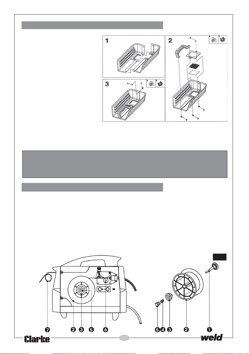
B. The Welding Shield
1. Push the two halves of the
shield together as shown.
2. Place the handle into
position and secure using
the plastic screw and clip
provided
3. Working from the inside of
the shield, insert the clear
glass panel into the recess
in the shield, followed
by the dark glass panel.
4. Secure the glass panels
with the lens surround and
plastic screws/clips
provided. The clear glass MUST be on the outside of the shield.
5. Finally use the last plastic screw and clip as shown to fix the two halves of the
shield together.
WARNING:
NEVER look at an electric arc without eye protection as this can injure the
eyes permanently. ALWAYS use a protection mask or welding helmet.
C. Installing the Welding Wire
NOTE: These machines are designed to accept either the Clarke ‘Mini’ or 5kg wire
spools of mild steel, stainless steel or aluminium according to the type of metal you
wish to weld. Mini Mild Steel wire spools are supplied with the machine...others
must be purchased separately. See ‘Accessories’ or your Clarke dealer for full
details.
1. IMPORTANT: Ensure that the gas and electrical supplies are disconnected.
2. (Ref. Fig. 2). To fit the wire spool (2), firstly pull open the cover, on the left hand
side of the unit, by inserting your finger in the hole provided and pulling sharply.
Fig.2
16
Page 17
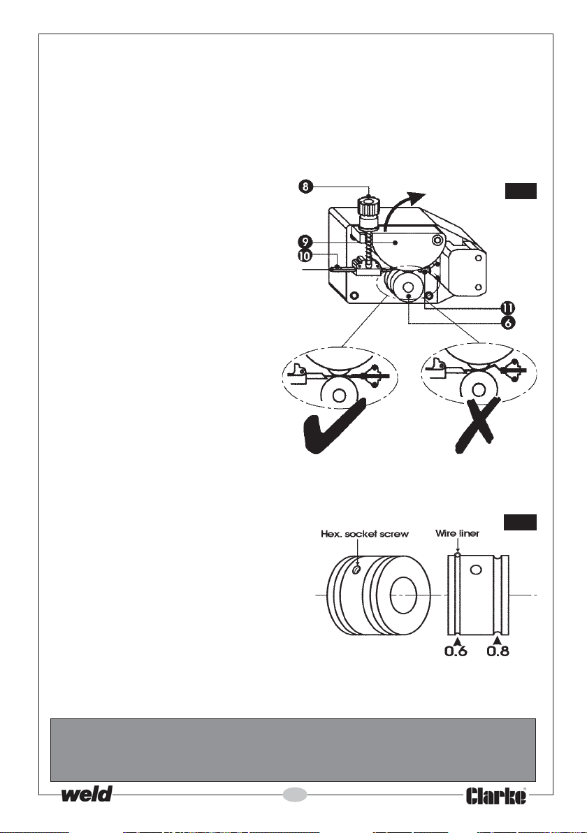
Unscrew and remove the plastic knob (5), followed by the spring (4) and collar (3)
from the hub (1). (If the spool is already fitted during initial assembly, remove the
plastic covering).
3. Slide the spool over the hub, ensuring that it sits snugly, and replace the collar, spring
and plastic knob, tightening it sufficiently to allow the spool to rotate smoothly but
with a slight amount of braking friction. Do not over tighten as this will exert undue
pressure on the wire drive motor and may cause serious damage.
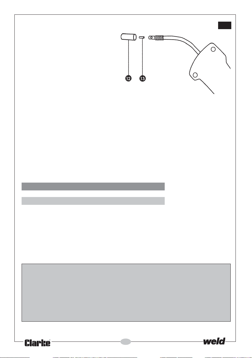
4. (Ref. Fig. 3)
Loosen the plastic knob (8) by turning
it anticlockwise, (this device maintains
pressure on the wire).
Pull, on the plastic knob, so that
the screw rod hinges out of its slot.
This releases the pivoted pressure
roller bracket (9). Raise the
bracket, in the direction of the
arrow, and pull out any wire that
has been left in the wire liner (11).
5. If you are changing the size of
wire, you must also select the
appropriate groove on the feed
roller (6) - see Fig.3A.
To change to the other groove,
undo the Hex. Socket Screw, shown
in Fig.3A, and remove the roller
from its shaft. Turn it through 180
replace it on the shaft, and adjust
so that the groove is directly in line
with the Wire Liner, as shown. Firmly
secure it in that position with the
Hex. Socket Screw.
6. Clip the end of the wire cleanly,
ensuring there are no burrs or sharp
edges, and, ensuring it is straight
(see: Fig.3), feed it through the guide
tube (10), over the channel on the
roller (6) and into the wire liner (11), by
approx. 10 - 15cm.
O
,
wire straight
Fig.3
wire bent
Fig.3A
7. Reposition the pressure roller bracket (9) and plastic knob (8) and tighten slightly.
CAUTION:
Tightening the knob (8) too tightly will crush the wire and damage the wire
feed motor, too loose will not allow the wire to be pulled by the roller.
17
Page 18
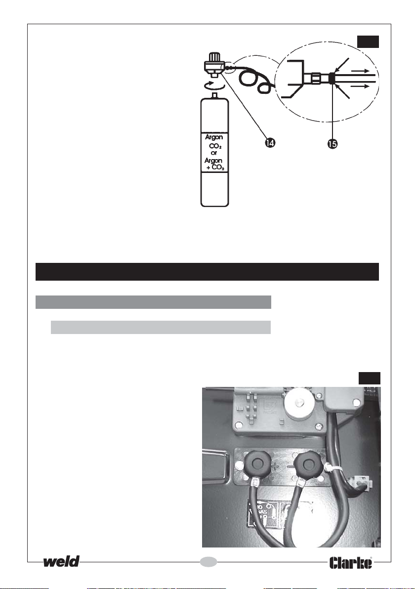
8. (Ref. Fig 4)
Unscrew and pull off the torch
shroud (12) by twisting it anti
clockwise, then unscrew the
contact tip (13).
Should any wire protrude from
the tip....pull it out completely
and discard.
Close the side panel of the
machine, plug into a 230V, 50HZ
outlet (or switch on isolator),
switch on the machine and
press the trigger.
The wire will feed through the hose and when it appears at the torch end,
release the trigger, switch off the machine and disconnect the machine from
the mains supply. Replace the contact tip and the torch shroud.
IMPORTANT:
Ensure the hose is kept straight during this operation, to assist the wire as it
is fed through to the wire liner and contact tip.
D. The Gas Supply
Fig.4
MIG 110E, 135TE and 151TE ONLY
NOTES:
These models require the gas bottle and regulator, to be fitted.
A mini gas bottle complete with gas regulator is provided. Should you prefer to use
larger gas cylinders, the appropriate gas regulator and fittings need to be
acquired. Your Clarke dealer will be happy to advise in this regard.
Always use the appropriate gas for the material being welded. Three types are
provided by Clarke International, as follows:
Carbon Dioxide (CO
Argon .................................... For Aluminium................... Part No. 6000661
CO2/Argon Mix ................... For Thin Sheet metal
Additionally a larger CO2 bottle is available ............... Part No. 6000643
Replacement Gas Regulator .......................................... Part No. 8132000
)......... For Mild Steel .................... Part No. 6000642
2
Mild Steel/ Stainless ......... Part No. 6000660
18
Page 19
Attach the mini gas bottle to the
machine as described in ‘Assembly’
on page 15, then connect up as
follows: (Ref. Fig. 5)
1. Remove the protective cap
from the cylinder outlet and
screw on the regulator (14),
fully, BUT DO NOT OVERTIGHTEN.
2. Simply push the gas hose, at the
rear of the machine, into the
gas regulator outlet, as far as
possible and release. This is a self
sealing coupling.
To remove the hose, hold back the
ring (15) then pull the hose out.
All components are now correctly
attached, and the welder may now be prepared for operation, as follows:
PREPARATION FOR USE
A.Electrical Connections
Fig.5
1. NO-GAS WELDING (EN Models ONLY)
IMPORTANT: ENSURE THE ELECTRICAL CONNECTIONS WITHIN THE WELDERS SIDE
COMPARTMENT ARE CORRECTLY CONNECTED...as follows:
TORCH to the NEGATIVE (-ve) terminal,
EARTH cable to the POSITIVE (+ve)
terminal.
The terminals within the side
compartment are shown in Fig. 6
19
Fig.6
Page 20
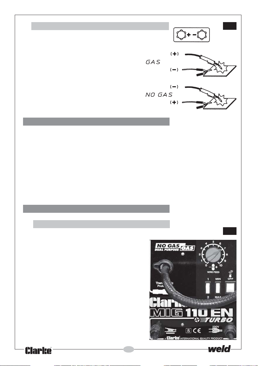
2. GAS WELDING
Connections should be
made as follows:
TORCH to the POSITIVE (+ve) terminal,
EARTH cable to the NEGATIVE (-ve)
terminal.
B. Welding Gas
(Models 130E, 135TE and 151TE ONLY)
The Gas Regulator Knob turns on a graduated plate, marked from 0 to 6.
With the knob pointer set to zero (0) the gas flow is OFF.
Set the Regulator to 3 or 4 which will provide a gas flow of 2-3 litres per
minute. This volume will provide adequate gas for a good weld without
porosity under normal conditions.
ALWAYS close the regulator by turning the knob to the 0 (zero) position
whenever you finish welding, or when changing gas cylinders.
Fig.7
C. Set the Controls
1. Models 110E, 110EN, 130EN & 135EN
These models are provided with two,
2-position switches and a rotary knob, as
shown in Fig. 8.
The rotary knob, with graduations from
0 to 10, is used to control the wire speed.
Two of the 2-position switches are marked
1- 2 and Max - Min respectively, and are
used to control the welding current
according to the type and thickness of
material to be welded, and in
accordance with the charts shown in the
‘Reference Tables’ on pages 24 and 25.
The remaining 2-position switch is the ON/
OFF switch
20
Fig.8
Page 21
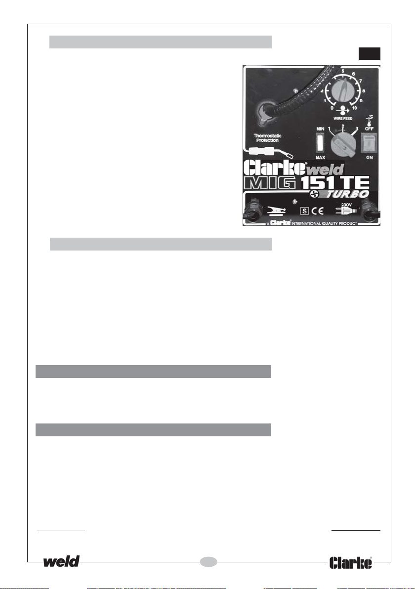
2. Models 151TE and 160EN
Fig.9
These models are provided with an ON/
OFF switch, a rotary knob, with
graduations marked from 0 to 10, a single
two position switch marked Max - Min,
and a 3-position rotary switch as shown
in Fig.9.
The 10-position rotary switch is used to
control wire speed, and the other two
switches are used to control the welding
current according to the type and
thickness of material to be welded, and
in accordance with the charts shown in
the ‘Reference Tables’ on pages 24 and
25. Set the controls accordingly.
3. ALL Models
The 10-position wire speed control should be set to 6 to begin with for welding steel,
and 9 for welding aluminium, then adjusted as required.
Note: This control is for fine tuning the wire speed. The speed of wire delivery will increase
automatically as the current is increased and vice versa. Therefore, once the ideal speed
is achieved, by fine tuning,it should not be necessary to adjust this control when the
welding current is changed.
It is always better to start with too high a speed, and back off slightly, to avoid the possibility
of the wire welding itself to the tip.
D. Trim the Welding Wire
Trim the welding wire so that it protrudes no more than 5mm from the end of the
shroud.
E. Attach the Earth Lead
Attach the earth lead to the workpiece with the earth clamp, as close to the
point of weld as possible, without it being intrusive.
Ensure there is good contact, if necessary, clean the area with a wire brush
beforehand.
Your welder is now fully prepared for welding.
21
Page 22
OPERATION
Plug the machine into the mains supply or switch on at the isolator and ensuring
all precautions have been taken and with the machine set up correctly, lower
the torch to the workpiece with one hand, whilst holding the welding mask in the
other.
Approach the work with the tip at an angle of approx. 45O and pull the torch
trigger fully.
As the electrode touches the workpiece, an arc will be struck......before it is struck,
cover the face with the face mask.
Simultaneously gas will be generated, if the wire is flux cored, or gas will be issued
if you are gas welding, and the wire will be fed into the molten pool.
Maintain a gap of approx. 5 - 7mm from the workpiece to the tip.
The speed of weld will depend upon the wire speed and welding current. It is
advisable to test your settings on a scrap piece of metal with similar characteristics
to those of the workpiece. Fine tune the welding speed and/or current flow, as
required, until a satisfactory weld is achieved.
Listen to the sound made. An irregular crackling sound denotes too high a wire
speed. Decrease the speed until a regular, strong buzzing sound is heard.
Whenever the welding current regulation is changed, a corresponding change
in wire speed may be necessary. If the speed is too slow, the wire will weld itself to
the tip.
WELDING TIPS
1. Try to maintain the tip of the nozzle at an angle of approx. 45O and at a constant
distance of approx 5-7mm from the workpiece.
2. Try to maintain a constant speed of movement with the torch.
3. Do not weld in windy conditions or in an area where ventilation is a problem,
or where air flow fluctuates.
4. ALWAYS keep the wire and nozzle clean...NEVER use rusted wire.
5. Avoid sharp bends or kinks in the welding hose.
6. Whenever possible, clean out the wire liner with compressed air when
replacing the wire spool.
7. Periodically remove the dust, using LOW PRESSURE compressed air, within the
casing. Adequate heat dissipation is essential during the welders operation.
22
Page 23
MAINTENANCE
Frequency of maintenance operations depends on the operating conditions, how
intensively the welder is used, and how clean or dirty the welding site is (aggressive
atmospheres, etc).
Always inspect the cables, both earth return and torch cable, before use to ensure
they are in perfect condition.
Ensure the earth clamp is clean and secured correctly to the cable.
Check the gas hose and Pressure Regulator for security and serviceability, and
ensure there is sufficient gas to complete the job in hand.
As a general rule the power supply should be inspected internally at least annually.
Consult your CLARKE dealer
WARNING!
ELECTRICITY CAN KILL
NEVER TOUCH LIVE ELECTRICAL COMPONENTS
DISCONNECT THE POWER SUPPLY BEFORE ALL INSPECTIONS AND
MAINTENANCE OPERATIONS
BEWARE HOT SURFACES.....ALWAYS LET THE POWER SUPPLY COOL DOWN
BEFORE ACCESSING INTERNAL COMPONENTS.
WELDING SHIELD
Always maintain the welding mask in good condition. If the clear glass protection
lens becomes badly pitted, sufficient to interfere with vision, or cracked, have it
replaced immediately.
Replacement clear and dark lenses are available from your Clarke dealer - see
Parts Lists for details. NEVER use any dark filter lens other than that provided by
CLARKE International, or one with the same certified ‘Optical class’ (degree of
protection).
The shield should always be cleaned with a clean soft cloth after use, ensuring
the lenses are clean. Remove any dust that may have accumulated and store it
in a safe place where it cannot be damaged.
The clear glass panel should be replaced when it becomes badly pitted.
NEVER use a shield that is not in perfect condition.
23
Page 24
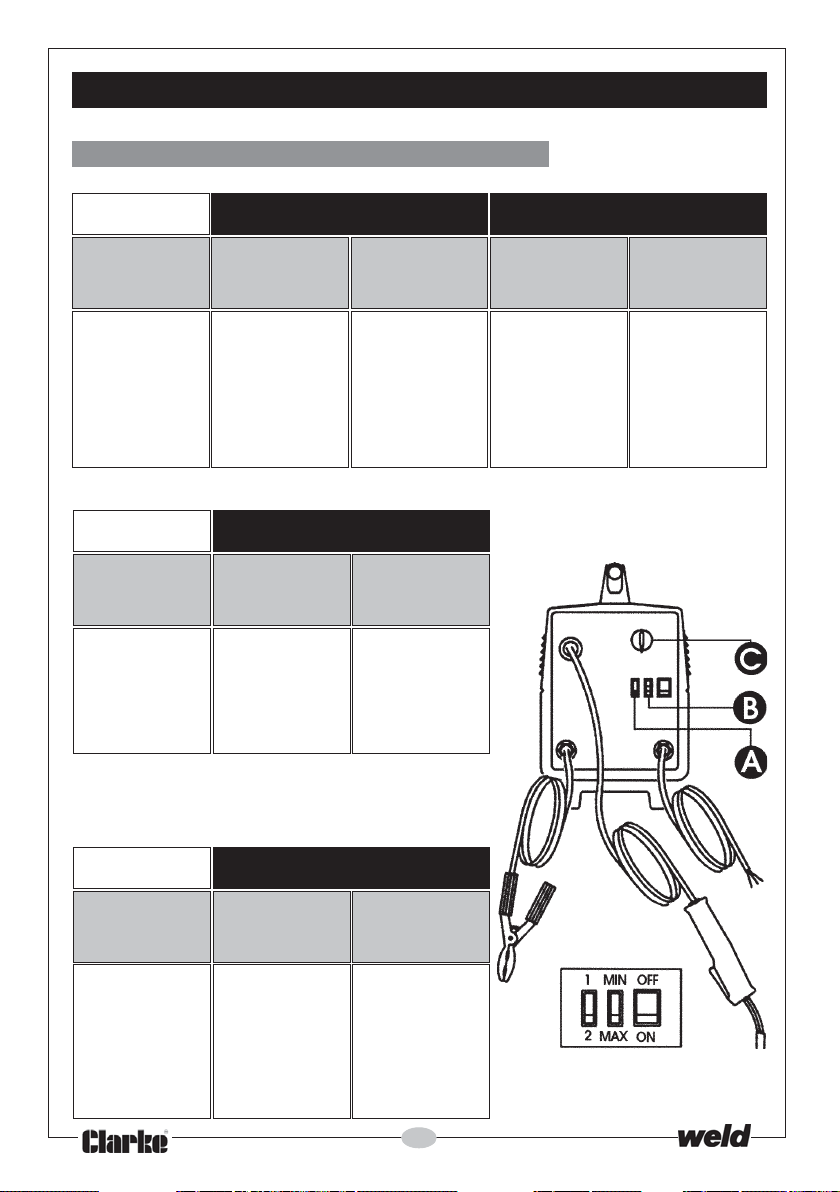
CONTROL SETTINGS - REFERENCE TABLES
A. MIGs 110E, 110EN, 130EN & 135TE
STEEL
Workpiece
Thickness
(mm)
0.6 - 0.8 1 MIN 5-6 1 MIN 5-6
0.8 - 1.0 1 MAX 5-6 1 MAX 5-6
1.0 - 2.0 2 MIN 6 2 MIN 6
2.0 - 3.0 2 MAX 7 2 MAX 7
ALUMINIUM
Workpiece
Thickness
(mm)
0.8 1 MIN 8-9
1.0 -2.0 1 MAX 9
2.0 - 3.0 2 MIN 9
0.6 mm Gas Welding Wire 0.8 mm Gas Welding Wire
Welding
Position
AB C AB C
Wire Speed
Adjustment
Welding
Position
0.8 mm Gas Welding Wire
Welding
Position
AB C
Wire Speed
Adjustment
Wire Speed
Adjustment
NO GAS
SOFT STEEL
Workpiece
Thickness
(mm)
0.6 - 0.8 1 MIN 5-6
0.8 - 1.0 1 MAX 5-6
1.0 - 1.2 2 MIN 6
1.2 - 2.0 2 MAX 7
0.9 mm Gas Welding Wire
Welding
Position
AB C
Wire Speed
Adjustment
24
Page 25
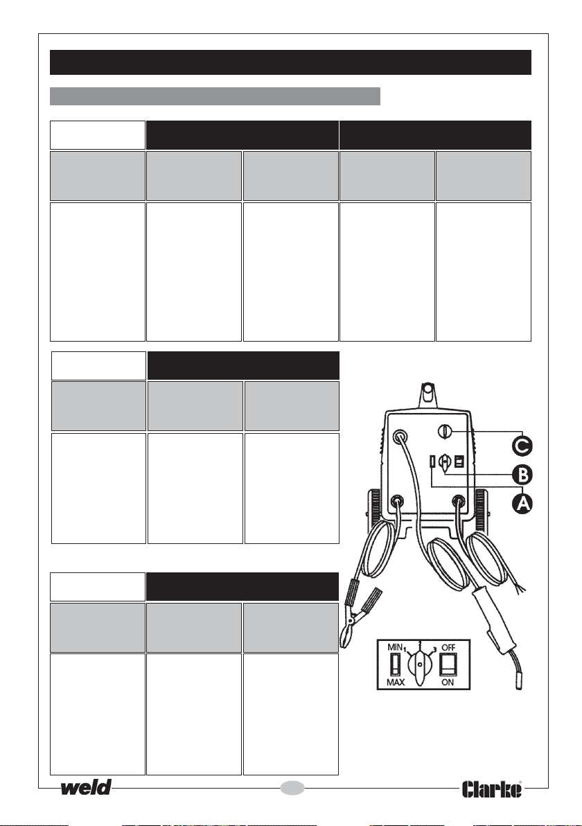
CONTROL SETTINGS - REFERENCE TABLES
B. MIGs 151TE & 160EN
STEEL
Workpiece
Thickness
(mm)
0.6 - 0.8 MIN 1 5-6 MIN 1 5-6
0.8 - 1.0 MAX 1 5-6 MAX 1 5-6
1.0 - 1.2 MIN 2 5-6 MIN 2 6
1.2 - 2.0 MAX 2 6 MAX 2 6
2.0 - 3.0 MIN 3 7 MIN 3 7
>3.0 MAX 3 7-8 MAX 3 7-8
ALUMINIUM
Workpiece
Thickness
(mm)
1.0 - 1.5 MIN 1 9
1.5 - 2.0 MAX 1 9
2.0 - 2.5 MIN 2 9
2.5 - 3.0 MAX 2 9
>3.0 MAX 2/3 10
0.6 mm Gas Welding Wire 0.8 mm Gas Welding Wire
Welding
Position
AB C AB C
Wire Speed
Adjustment
Welding
Position
0.8 mm Gas Welding Wire
Welding
Position
AB C
Wire Speed
Adjustment
Wire Speed
Adjustment
NO GAS
SOFT STEEL
Workpiece
Thickness
(mm)
0.9 MIN 1 5-6
0.9 - 1.0 MAX 1 5-6
1.0 - 1.2 MIN 2 5-6
1.2 - 2.0 MAX 2 6
2.0 - 3.0 MIN 3 7
>3.0 MAX 3 7-8
0.9 mm Gas Welding Wire
Welding
Position
AB C
Wire Speed
Adjustment
25
Page 26
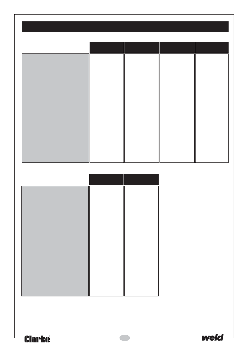
SPECIFICATIONS
110E 110EN 130EN 135TE
Power Supply(All Models) 230V 50Hz 1Ph 230V 50Hz 1Ph 230V 50Hz 1Ph 230V 50Hz 1Ph
Fuse Rating (All Models) 13Amps 13Amps 13Amps 13Amps
Current Range 30-100A 30-100A 30-130A 30-130A
Max. Metal Thickness 3mm 2-3mm 4-5mm 5mm
Welding Wire Sizes 0.6-0.8mm 0.6-0.9mm 0.6-0.9mm 0.6-0.8mm
Duty Cycle* 8% 100A - 130A 130A
15% - 100A 115A 115A
60% 40A 55A 57A 57A
100% 30A 40A 44A 44A
Dimensions (All Models) 500x280x420mm 500x280x420mm 500x280x420mm 500x280x420mm
Weight 24kg 24kg 24.5kg 28.5kg
Part No. 6015110 6014500 6014530 6015135
151TE 160EN
Power Supply(All Models) 230V 50Hz 1Ph 230V 50Hz 1Ph
Fuse Rating (All Models) 15Amps 15Amps
Current Range 30-150A 30-150A
Max. Metal Thickness 5-6mm 5-6mm
Welding Wire Sizes 0.6-0.8mm 0.6-0.9mm
Duty Cycle* 10% 150A 150A
20% 130A 130A
60% 75A 75A
100% 55A 55A
Dimensions (All Models) 500x280x420mm 500x280x420mm
Weight 24kg 24kg
Part No. 6015151 6014560
* Duty Cycle: Determines the machine ‘down time’.
eg MIG130-EN, operating at 57 Amps - Duty Cycle - 60%. This means that in ANY 10 minute period, the
machine may operate for 6 minutes and must have a down time of 4 minutes.
Please note that the details and specifications contained herein, are correct at the time of
going to print. However, CLARKE International reserve the right to change specifications at any
time without prior notice. ALWAYS CONSULT THE MACHINE’S DATA PLATE
26
Page 27
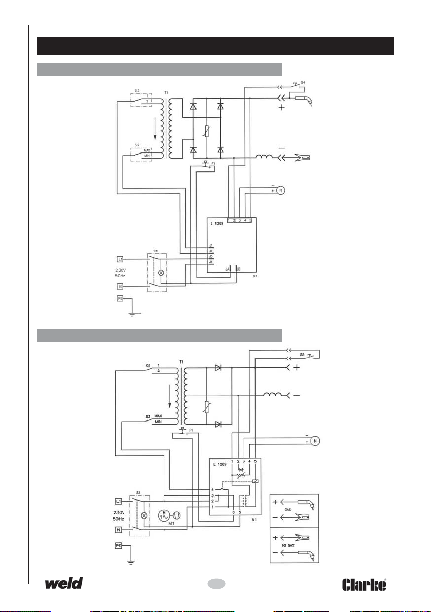
WIRING DIAGRAMS
MIG 110E
MIG 110EN
27
Page 28
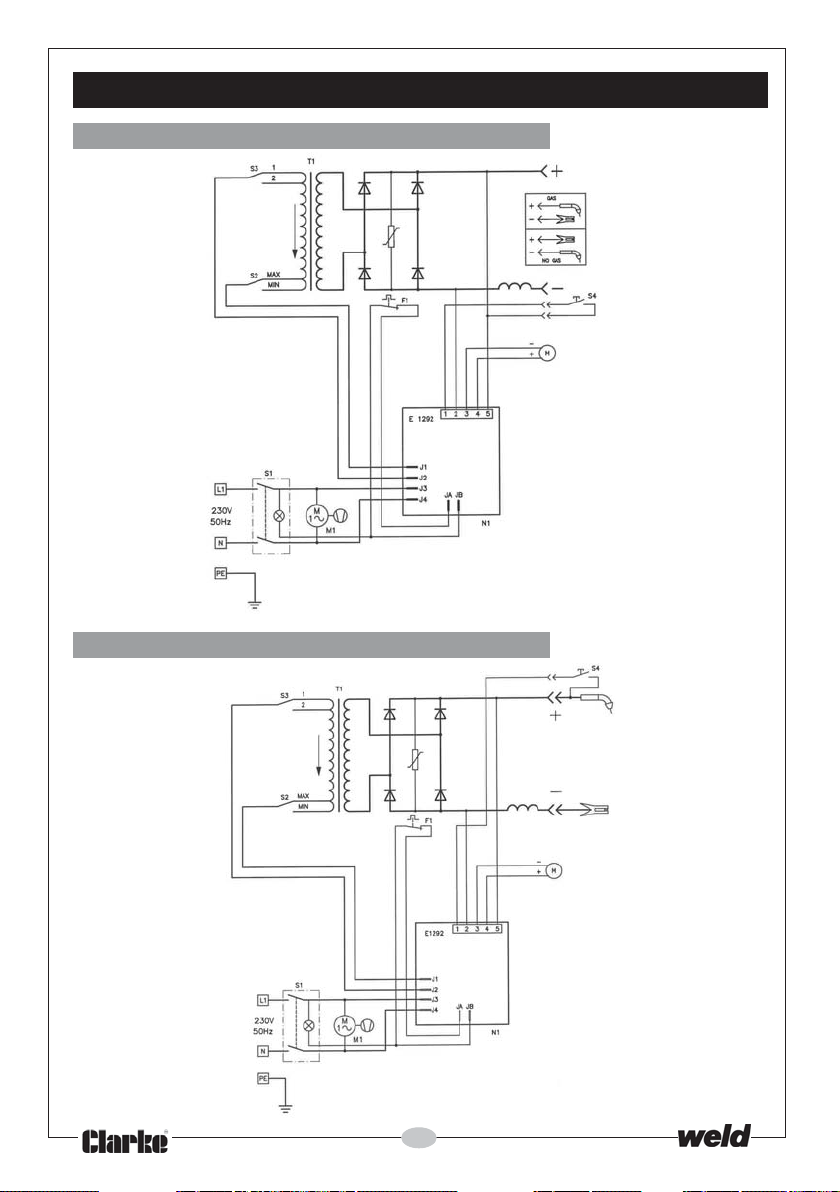
WIRING DIAGRAMS
MIG 130EN
MIG 135TE
28
Page 29
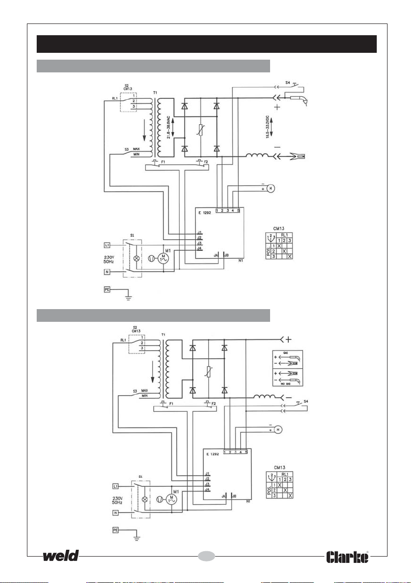
WIRING DIAGRAMS
MIG 151TE
MIG 160EN
29
Page 30
PARTS LIST - MIG 110E
No. Description Part No.
3
Wire Feeding Motor EM04600141
4
Complete Thermostat EM04600113
5
Plastic Handle EM21600021
7
Torch Grommet on Front Panel EM21690458
8
Welding Current Switch EM22200038
9
Potentiometer Knob EM21690310
11
Yellow Pilot-light Switch EM22200022
12
Access Panel Hinge EM21690178
13
Dividing Panel EM33720092
14
Wire Spool See Accessories
15
Fixed Spool Holder EM21690714
16
Spool Holder Retaining Ring EM21690715
17
Plastic Wire Feeder EM44400024
18
P.C. Board EM22710043
20
Cable Clamp EM21605010
21
Left Access Panel EM33705217
22
Front Panel EM33710165
24
Right-side Upper Panel EM33705216
25
Rear Panel EM33715063
27
Wire Feed Roll Knurled EM33805001
28
Front Plastic Frame EM21690175
29
Side Panel Clip EM21690177
30
Front Plastic Foot EM21610014
31
Choke EM44135097
32
Rectifier EM22400021
33
Transformer EM44120105
35
Back Plastic Foot EM21610015
36
Earthcable EM43210119
37
Earth Clamp EM22110043
38
Red Torch compl. EM23000050
39
Power Cable EM20220068
40
Back Plastic Frame EM21690176
41
Spool Holder Handwheel with nut EM21800069
42
Lower Panel EM33700138
43
Reducer W/Out Gauge EM22905001
44
Spare Cartridge C0
45
Hose Clamp EM22915004
46
Plastic Mask W/Handle EM21905065
47
Transparent Glass EM21905020
48
Dark Glass 82x108 BS Din11 EM21905021
2
See Accessories
30
Page 31
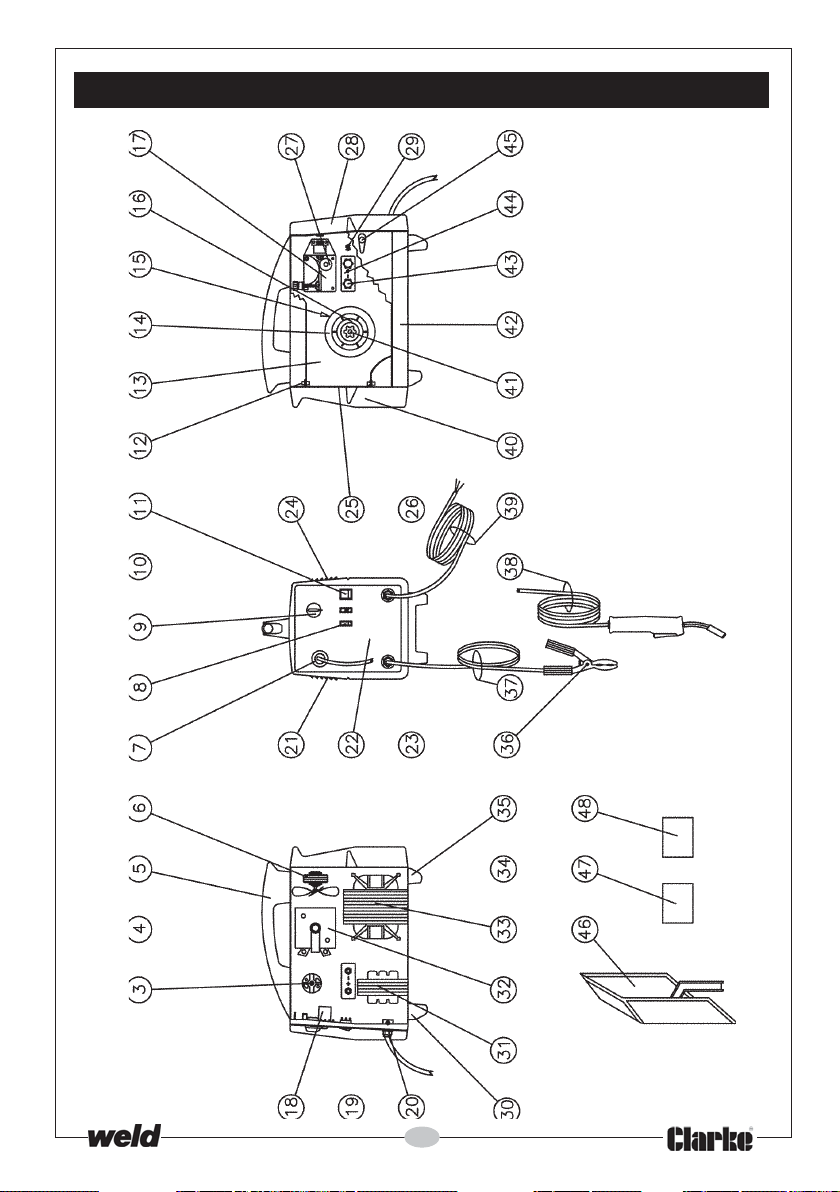
PARTS DIAGRAM - MIG 110E
31
Page 32
PARTS LIST - MIG110EN
No. Description Part No.
3
Wire Feeding Motor EM04600141
5
Plastic Handle EM21600021
6
Complete Fan EM04600055
7
Torch Grommet On Front Panel EM21690458
8
Welding Current Switch EM22200038
9
P.C. Board Knob EM21690310
11
Yellow Pilot-light Switch EM22200022
12
Side-panel Pin EM21690178
13
Dividing Panel EM33720063
14
Wire Spool See Accessories
15
Fixed Spool Holder EM21690714
16
Spool Holder Retaining Ring EM21690715
17
Plastic Wire Feeder EM44400024
18
P.C. Board EM22710043
20
Cable Clamp EM21605032
21
Left-side Panel EM33705217
22
Front Panel EM33710165
24
Right-side Upper Panel EM33705216
25
Back Panel EM33715063
27
Wire Feed Roll Knurled EM33805001
28
Front Plastic Frame EM21690175
29
2 Pins Male Connector EM22105040
29
Male Connector EM22105042
30
Front Plastic Foot EM21610014
31
Choke EM44135097
32
Rectifier EM22400001
33
Transformer + Thermostat EM44120068
35
Back Plastic Foot EM21610015
36
Earth Clamp EM22110043
37
Power Cable EM43210108
38
Torch Compl. EM23000049
39
Power Cable EM20220068
40
Back Plastic Frame EM21690176
41
Spool Holder Knob 4w/Nut EM21800069
42
Lower Panel EM33700138
43
4 Lobe Hand-wheel EM21800051
44
Gas/No Gas Change Board EM21800050
45
Side Panel Clip EM21690177
46
Plastic Mask W/Handle EM21905065
47
Transparent Glass EM21905020
48
Dark Glass 82x108 BS Din11 EM21905021
32
Page 33
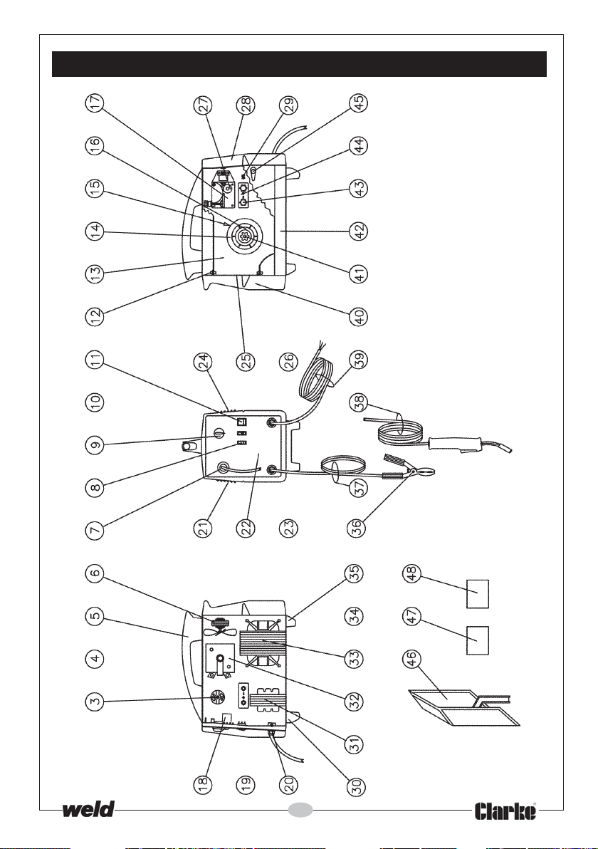
PARTS DIAGRAM - MIG 110EN
33
Page 34
PARTS LIST - MIG 130EN
No. Description Part No.
1
Handle-extension Grip EM21610032
2
Handle-extension EM33725054
3
Wire Feeding Motor EM04600141
4
Complete Thermostat 100 + Support EM04600113
5
Plastic Handle EM21600021
6
Complete Fan EM04600055
7
Torch Grommet On Front Panel EM21690458
8
Welding Current Switch EM22200038
9
Potentiometer Knob EM21690310
11
Yellow Pilot-light Switch EM22200022
12
Access Panel Hinge EM21690178
13
Dividing Panel EM33720063
14
Wire Spool See Accessories
15
Fixed Spool Holder EM21690714
16
Spool Holder Retaining Ring EM21690715
17
Plastic Wire Feeders EM44400024
18
P.C. Board EM22710043
20
Cable Clamp EM21605032
21
Left Access Panel EM33705217
22
Front Panel EM33710165
23
Wheels-axle EM55200014
24
Right-side Upper Panel EM33705216
25
Rear Panel EM33715063
26
Wheel EM21625034
27
Wire Feed Roll Knurled EM33805001
28
Front Plastic Frame EM21690175
29
2 Pins Male Connector EM22105040
29
Male Connector EM22105042
30
Front Plastic Foot EM21610014
31
Inductance EM44135123
32
Rectifier EM22400049
33
Transformer EM44120049
35
Back Plastic Foot EM21610015
36
Earth Clamp EM22110043
37
Earth Cable EM43210108
38
Torch compl. EM23000049
39
Power Cable w/Plug +13A Fuse EM20220068
40
Back Plastic Frame EM21690176
41
Spool Holder Handwheel with Nut EM21800069
42
Lower Panel EM33700138
43
4 Lobes Hand-wheel EM21800051
44
Gas/No Gas Change Board EM21800061
45
Side Panel Clip EM21690177
46
Plastic Mask W/Handle EM21905065
47
Transparent Glass EM21905020
48
Dark Glass 82x108 BS DIN11 EM21905021
34
Page 35
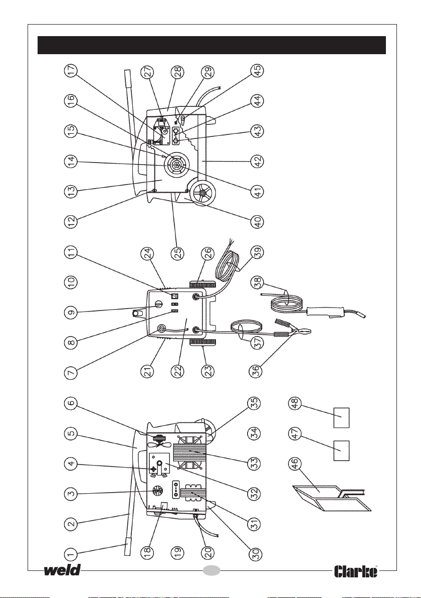
PARTS DIAGRAM - MIG 130EN
35
Page 36
PARTS LIST - MIG 135TE
No. Description Part No.
Handle-extension Grip EM21610032
1
Handle-extension EM33725054
2
Wire Feeding Motor EM04600141
3
Complete Thermostat EM04600113
4
Plastic Handle EM21600021
5
Complete Fan EM04600055
6
Torch Grommet On Front Panel EM21690458
7
Welding Current Switch EM22200038
8
Potentiometer Knob EM21690310
9
Yellow Pilot-light Switch EM22200022
11
Access Panel Hinge EM21690178
12
Dividing Panel EM33720092
13
Wire Spool See Accessories
14
Fixed Spool Holder EM21690714
15
Spool Holder Retaining Ring EM21690715
16
Plastic Wire Feeder EM44400024
17
P.C. Board EM22710043
18
Cable Clamp EM21605010
20
Left Access Panel EM33705217
21
Front Panel EM33710165
22
Wheels-axle EM55200014
23
Right-side Upper Panel EM33705216
24
Rear Panel EM33715063
25
Wheel EM21625034
26
Wire Feed Roll Knurled EM33805001
27
Front Plastic Frame EM21690175
28
Side Panel Clip EM21690177
29
Front Plastic Foot EM21610014
30
Inductance EM44135123
31
Rectifier EM22400049
32
Transformer EM44120049
33
Back Plastic Foot EM21610015
35
Earth Cable EM43210119
36
Earth Clamp EM22110043
37
Red Torch EM23000050
38
Input Cable, Plug + 13A Fuse EM20220068
39
Back Plastic Frame EM21690176
40
Spool Holder Handwheel With Nut EM21800069
41
Lower Panel EM33700138
42
Reducer W/Out Gauge EM22905001
43
Spare Cartridge C02 See Accessories
44
Hose Clamp EM22915004
45
Plastic Mask W/Handle EM21905065
46
Transparent Glass EM21905020
47
48
Dark Glass 82x108 BS Din11 EM21905021
36
Page 37
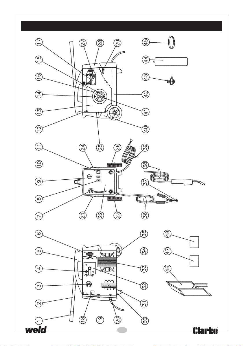
PARTS DIAGRAM - MIG 135TE
37
Page 38
PARTS LIST - MIG 151TE
No. Description Part No.
1
Handle-extension Grip EM21610032
2
Handle-extension EM33725054
3
Wire Feeding Motor EM04600145
4
Thermostat EM04600113
5
Plastic Handle EM21600021
6
Complete Fan EM04600055
7
Torch Grommet EM21690458
8
Welding Current Switch EM22200038
9
P.C. Board Knob EM21690310
10
Switch Knob EM21690312
11
Yellow Pilot-light Switch EM22200022
12
Side-panel Pin EM21690178
13
Dividing Panel EM33720092
14
Wire Spool See Accessories
15
Fixed Spool Holder EM21690714
16
Spool Holder Retaining Ring EM21690715
17
Plastic Wire Feeder EM44400016
18
P.C. Board EM22710043
19
Switch EM22205001
20
Cable Clamp EM21605010
21
Left-side Panel EM33705217
22
Front Panel EM33710194
23
Wheels-axle EM55200014
24
Right-side Upper Panel EM33705216
25
Back Panel EM33715063
26
Wheel EM21625034
27
Wire Feed Roll Knurled EM33805001
28
Front Plastic Frame EM21690175
29
Side Panel Clip EM21690177
30
Front Plastic Foot EM21610014
31
Choke EM44135018
32
Rectifier EM22400038
33
Transformer EM44120173
34
Thermostat EM22210016
35
Back Plastic Foot EM21610015
36
Earth Cable EM43210119
37
Earth Clamp EM22110043
38
Red Torch EM23000050
39
Input Cable EM20220014
40
Back Plastic Frame EM21690176
41
Spool Holder Knob EM21800069
42
Lower Panel EM33700138
43
Regul. W/Out Gauge EM22905001
44
Spare Cartridge See Accessories
45
Hose Clamp EM22915004
46
Plastic Mask W/Handle EM21905065
47
Transparent Glass EM21905020
48
Dark Glass 82x108 BS Din11 EM21905021
38
Page 39
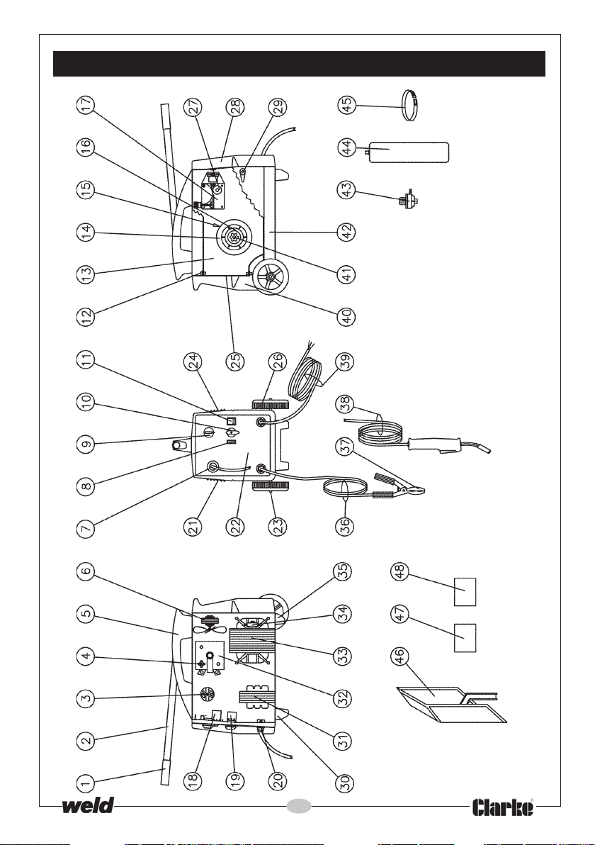
PARTS DIAGRAM - MIG 151TE
39
Page 40
PARTS LIST - MIG 160EN
No. Description Part No.
1
Handle-extension Grip EM21610032
2
Handle-extension EM33725054
3
Wire Feeding Motor EM04600145
4
Thermostat EM04600113
5
Plastic Handle EM21600021
6
Complete Fan EM04600055
7
Torch Grommet EM21690458
8
Welding Current Switch EM22200038
9
P.C. Board Knob EM21690310
10
Switch Knob EM21690312
11
Yellow Pilot-light Switch EM22200022
12
Side-panel pin EM21690178
13
Dividing Panel EM33720063
14
Wire Spool See Accessories
15
Fixed Spool Holder EM21690714
16
Spool Holder Retaining Ring EM21690715
17
Plastic Wire Feeder EM44400016
18
P.C. Board EM22710043
19
Switch EM22205001
20
Cable Clamp EM21605032
21
Left-side Panel EM33705217
22
Front Panel EM33710194
23
Wheels-axle EM55200014
24
Right-side Upper Panel EM33705216
25
Back Panel EM33715063
26
Wheel EM21625034
27
Wire Feed Roll Knurled EM33805001
28
Front Plastic Frame EM21690175
29
2 Pins Male Connector EM22105040
29
Male Connector EM22105042
30
Front Plastic Foot EM21610014
31
Choke EM44135018
32
Rectifier EM22400038
33
Transformer EM44120173
34
Thermostat EM22210016
35
Back Plastic Foot EM21610015
36
Earth Clamp EM22110043
37
Earth Cable EM43210108
38
Torch compl. EM23000049
39
Input Cable EM20220014
40
Back Plastic Frame EM21690176
41
Spool Holder Knob w/Nut EM21800069
42
Lower Panel EM33700138
43
4 Lobes Hand-wheel EM21800051
44
Gas/No Gas Change Board EM21800051
45
Side Panel Clip EM21690177
46
Plastic Mask W/Handle EM21905065
47
Transparent Glass EM21905020
48
Dark Glass 82x108 BS Din11 EM21905021
40
Page 41
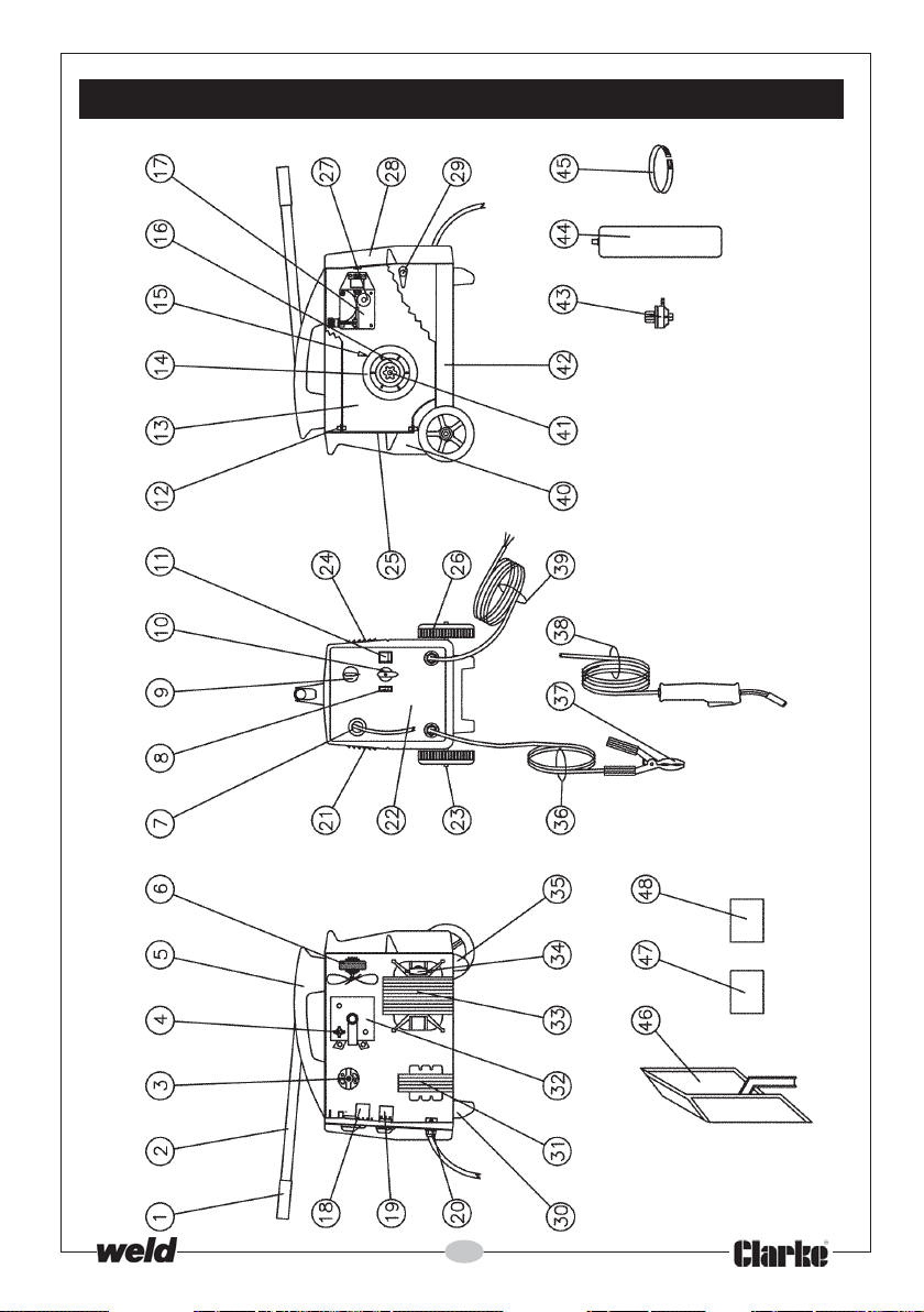
PARTS DIAGRAM - MIG 160EN
41
Page 42
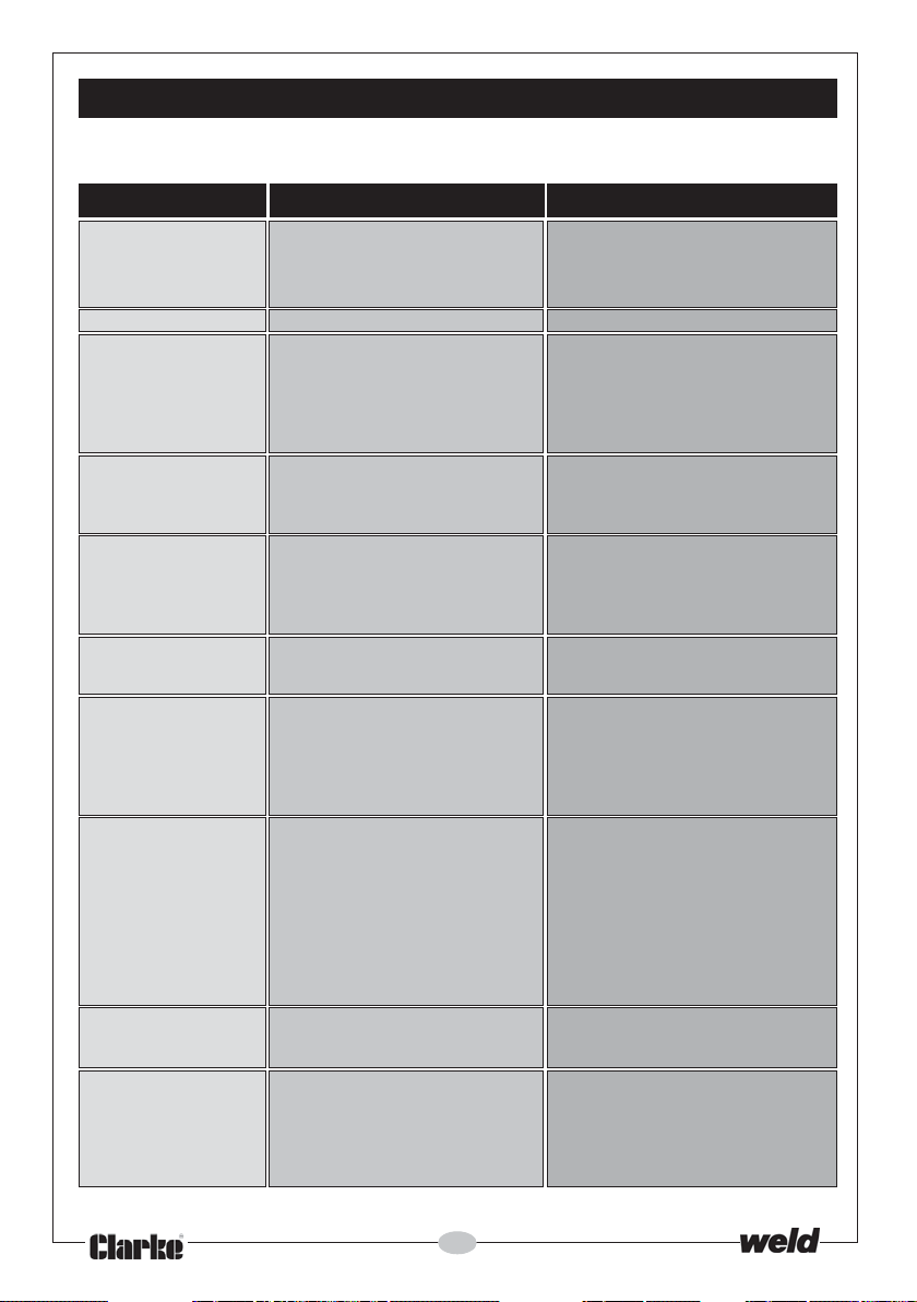
TROUBLESHOOTING
Your Clarke Mig Welder has been designed to give long and trouble free service. If,
however, having followed the instructions in this booklet carefully, you still encounter
problems, the following points should help identify and resolve them.
PROBLEM CAUSE REMEDY
1. No “life” from welder Check fuses and mains lead a) Replace fuses as necessary If
2. No wire feed Motor malfunction Return welder to your local dealer
3. Feed motor operates a) Insufficient Feed Roller Pressure a) Increase roller pressure
but wire will not feed b) Burr on end of wire b) Re-cut wire square with no burr
4. Wire welds itself to tip a) Wire feed speed too low a) Unscrew tip, cut wire and fit new tip
5. Wire feeds into ‘birds a) Wire welded to tip a) As above plus reduce feed roller
nest’ tangle pressure so that if blockage occurs
6. Loose coils of wire Drum brake too slack Tighten drum brake
tangle around wire Caution: Do not over-tighten
drum inside machine
7. Erratic wire feed a) Drum brake too tight a) Loosen drum brake slightly
8. Poor quality welds a) Insufficient gas at weld area a) Check that gas is not being blown
9. Wire jams in tip when Tip too small Use slightly oversize tip ie., for .8mm
welding aluminium wire use 1mm tip. (Note: Applies to
10. Welder cuts out Duty cycle exceeded Allow welder to cool 15-30 mins
whilst in use (auto cut-out operates) before continuing
If you have any problems which cannot be resolved by reference to the above, or if you
require spare parts for your welder please contact your local Clarke dealer.
c) Liner blocked or damaged c) Clean with compressed air or
d) Inferior wire d) Use only good “clean” wire
e) Roller worn out e) Replace roller
b) Wrong size tip b) Fit correct size tip
b) Wire liner damaged preventing
smooth operation b) Renew wire liner
b) Feed roller worn b) Check and replace if necessary
c) Insufficient pressure on feed roller c) Increase pressure on feed roller
d) Wire dirty, rusty, damp or bent d) Re-cut wire and ensure it is clean
e) Liner partially blocked e) Clean with compressed air
b) Incorrect gas/wire combination b) Consult your MIG welding manual
c) Rusty, painted, damp, oil or c) Ensure workpiece is clean and dry
greasy workpiece
d) Rusty/dirty wire d) Ensure wire is clean and dry
e) Poor earth contact e) Check earth clamp/workpiece conn
42
problem persists return welder to
your local dealer
b) Check fuse size
replace liner.
Increase wire speed before
operating again
wire slips on roller i.e. no feed
Caution: Do not over-tighten
away by draughts and if so move
to more sheltered weld area. If not
increase gas supply
for correct set-up
aluminium only)
Note: If duty cycle is continually
exceeded, damage to the welder
may result, and welder output is
probably too small for application
Page 43
ACCESSORIES
The following accessories are available from your Clarke dealer. Please quote
the part numbers shown below:
Welding Wire Spools
1.
Mild Steel Stainless Steel Aluminium
Mini - 0.6mm 6000641 - -
Mini - 0.8mm 6000481 6000498 6000483
Mini - 9mm (FLUX Core) 6000664 - -
5kg - 0.6mm 6000476 - -
5kg - 0.8mm 6000475 - -
4.5-5kg - 9mm (FLUX Core) 6000666 - -
2. Welding Gas
CO2 (250g) 6000642 For welding Mild Steel
CO
(600g) 6000643 For welding Mild Steel
2
Argon 6000661 For welding Aluminium
CO2/Argon Mix 6000660 For welding Stainless/Thin Sheet MS
3. Welding Tips
0.6mm (pack of 5) 8132260
0.8mm (pack of 5) 8132270
4. Gas Regulator 8132000
In addition to the above, your Clarke dealer can provide you with a wide range
of welding accessories, safety equipment etc., to increase productivity where
necessary and to simplify and assist in the welding process.
PARTS AND SERVICE CONTACTS
For Spare Parts and Service, please contact your nearest dealer,
or CLARKE International, on one of the following numbers.
PARTS & SERVICE TEL: 020 8988 7400
PARTS & SERVICE FAX: 020 8558 3622
or e-mail as follows:
PARTS: [email protected]
SERVICE: [email protected]
43
Page 44

 Loading...