

Page 1
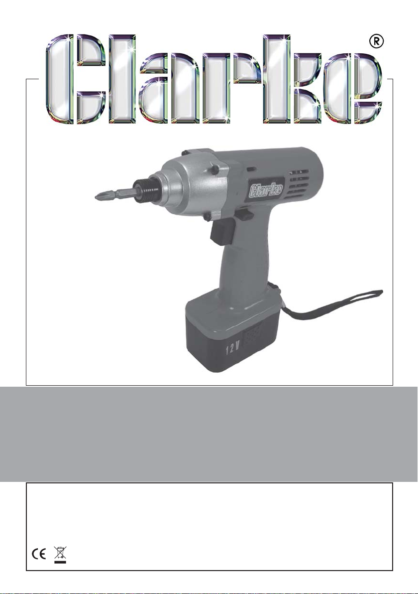
PROFESSIONAL CORDLESS
IMPACT SCREWDRIVER
Model CIS100
Part No 4500625
OPERATING & MAINTENANCE
INSTRUCTIONS
GC0609
Page 2
INTRODUCTION
Thank you for purchasing this CLARKE Impact Screwdriver.
Before attempting to operate the machine, it is essential that you read this
manual thoroughly and carefully follow all instructions given. In doing so you
will ensure the safety of yourself and that of others around you, and you can
also look forward to the product giving you long and satisfactory service.
GUARANTEE
This CLARKE product is guaranteed against faulty manufacture for a period of
12 months from the date of purchase. Please keep your receipt as proof of
purchase.
This guarantee is invalid if the product is found to have been abused or
tampered with in any way, or not used for the purpose for which it was
intended.
Faulty goods should be returned to their place of purchase, no product can
be returned to us without prior permission.
This guarantee does not effect your statutory rights.
ENVIRONMENTAL PROTECTION
Do not dispose of this product with general household waste. All tools,
accessories and packaging should be sorted, taken to a recycling
centre and disposed of according to the laws governing Waste
Electrical and Electronic Equipment.
BATTERIES - DISPOSAL
Dispose of old batteries in accordance with local regulations. Do not
incinerate or crush, as this will increase the risk of explosion and
contamination. If the battery contents come into contact with skin or the
eyes, rinse with clean water for several minutes and seek medical advice
immediately afterwards.
2
Page 3

CONTENTS
Introduction ............................................................................................ 2
Guarantee .............................................................................................. 2
Environmental Protection ...................................................................... 2
Component Inventory ........................................................................... 3
Safety Precautions ................................................................................. 4
Safety Symbols ....................................................................................... 5
Electrical Connections .......................................................................... 6
Component Identification .................................................................... 7
Initial Battery Charging ......................................................................... 7
Installing & Removing the Bit ................................................................ 9
Operation ............................................................................................... 9
Maintenance ........................................................................................ 10
Parts & Service Contacts ..................................................................... 10
Technical Specifications ..................................................................... 11
Parts List and Diagram......................................................................... 12
Declaration of Conformity .................................................................. 14
COMPONENT INVENTORY
The CIS100 is a professional, rechargeable cordless impact screwdriver.
Upon receipt, unpack and lay out the components, checking against the
following list. Any damage or deficiency should be reported to your CLARKE
dealer immediately.
1. 12V Impact screwdriver with 1.7a/h battery pack
2. Battery-charging unit
3. Moulded Tool-case
4. 2 x Double-ended phillips no2 screwdriver bits, 1/4”( 6.35mm)
5. Operators manual (this document)
3
Page 4

SAFETY PRECAUTIONS
WORK ENVIRONMENT
1. Keep the work area clean and tidy.
2. Dress appropriately - do not wear loose clothing or jewellery. Tie long hair
out of the way.
3. Keep children and visitors away - do not let children handle the
screwdriver.
4. DO NOT use in damp or wet conditions. Keep the work area well lit. Do not
use where a risk of fire or explosion is present.
5. Although the impact screwdriver may be used outdoors, DO NOT leave it
exposed to the elements. Avoid direct sunlight, direct heat, rain/moisture
etc.
6. Always keep body and clothing dry. Never work in damp area without
adequate insulation against electric shock.
7. Do not fit the screwdriver to any stand or clamping device that may
damage it.
GENERAL USE
1. This product vibrates during use. Vibration may be harmful to your hands
or arms. Stop using the machine if discomfort, a tingling feeling or pain
occurs and seek medical advice before resuming use.
2. ALWAYS use ear defenders.
3. ALWAYS stay alert and use common sense - do not use this product when
you are tired or under the influence of alcohol or medication.
4. ALWAYS ensure the workpiece is firmly secured leaving both hands free to
control the impact screwdriver.
5. ALWAYS wear eye protection when using this product - eye protection
must provide protection from the front and the side.
6. ALWAYS ensure the machine has stopped before putting it down after use.
7. ALWAYS set the forward/reverse switch-bar to neutral when changing bits
or when the machine is not required for immediate use.
8. ALWAYS ensure that any bits are correctly installed before switching on.
9. A LWAYS store this product in a dry, secure place out of reach of children.
10. ALWAYS keep all equipment dry especially the battery & battery charger.
11. ALWAYS check for any damage or any condition that could affect its
operation. Any damaged part should be properly repaired.
12. NEVER carry out any alterations or modifications to this product.
4
Page 5
13. NEVER force or misuse the machine It will do a better and safer job at the
rate for which it was designed.
14. NEVER over-reach. Keep proper footing and balance at all times.
15. NEVER use this product for any other purpose than that described in this
booklet.
16. NEVER use this product if it is defective / operating abnormally.
17. NEVER abuse the mains cable of the battery charger. Never yank the
cable to disconnect it from the socket. Keep the cable away from sharp
edges/hot surfaces.
18. NEVER attempt to wipe the machine clean with solvents. Wipe plastic
parts with a soft cloth, slightly dampened with soapy water.
19. NEVER attempt any repairs yourself. If you have a problem with this
product contact your local CLARKE dealer.
SAFETY SYMBOLS
The full technical specification of the battery charger is printed on a label on
the charger. The meanings of the markings and symbols are shown below.
Class II appliance which does not need an earth connection
For indoor use only
Read the manual before operating this machine
Falls under the Waste Electrical & Electronic Equipment directive
(WEEE)
European Certificate of Conformance
5
Page 6
ELECTRICAL CONNECTIONS
This battery charger is provided with a 13 amp, 230 volt (50Hz), BS 1363 plug,
for connection to a standard, domestic electrical supply. Should the plug
need changing at any time, ensure that a plug of identical specification is
used.
This appliance is of double insulated design
No earth conductor is provided. The two wires in the mains lead should be
wired up in accordance with the following colour code:
Blue — Neutral
Brown — Live
Connect the BROWN coloured cord to the plug terminal marked a letter “L”
Connect the BLUE coloured cord to the plug terminal marked a letter “N”
If this appliance is fitted with a plug which is moulded on to the electric cable
(i.e. non-rewireable) please note:
1. The plug must be thrown away if it is cut from the electric cable. There is a
danger of electric shock if it is subsequently inserted into a socket outlet.
2. Never use the plug without the fuse cover fitted.
3. Should you wish to replace the fuse cover, ensure that the correct
replacement is used (as indicated by marking or colour code).
4. Replacement fuse covers can be obtained from your local Clarke dealer
or most electrical stockists.
FUSE RATING
The fuse in the plug must be replaced with one of the same rating and this
replacement must be ASTA approved to BS1362.
If in any doubt, consult a qualified electrician. DO NOT attempt any electrical
repairs yourself.
CABLE EXTENSION
Do not use an extension longer than 10 metres and one where the
conductors, are less than 1.5mm2.
If used outdoors, ensure the extension cable is designed for outdoor use.
6
Page 7
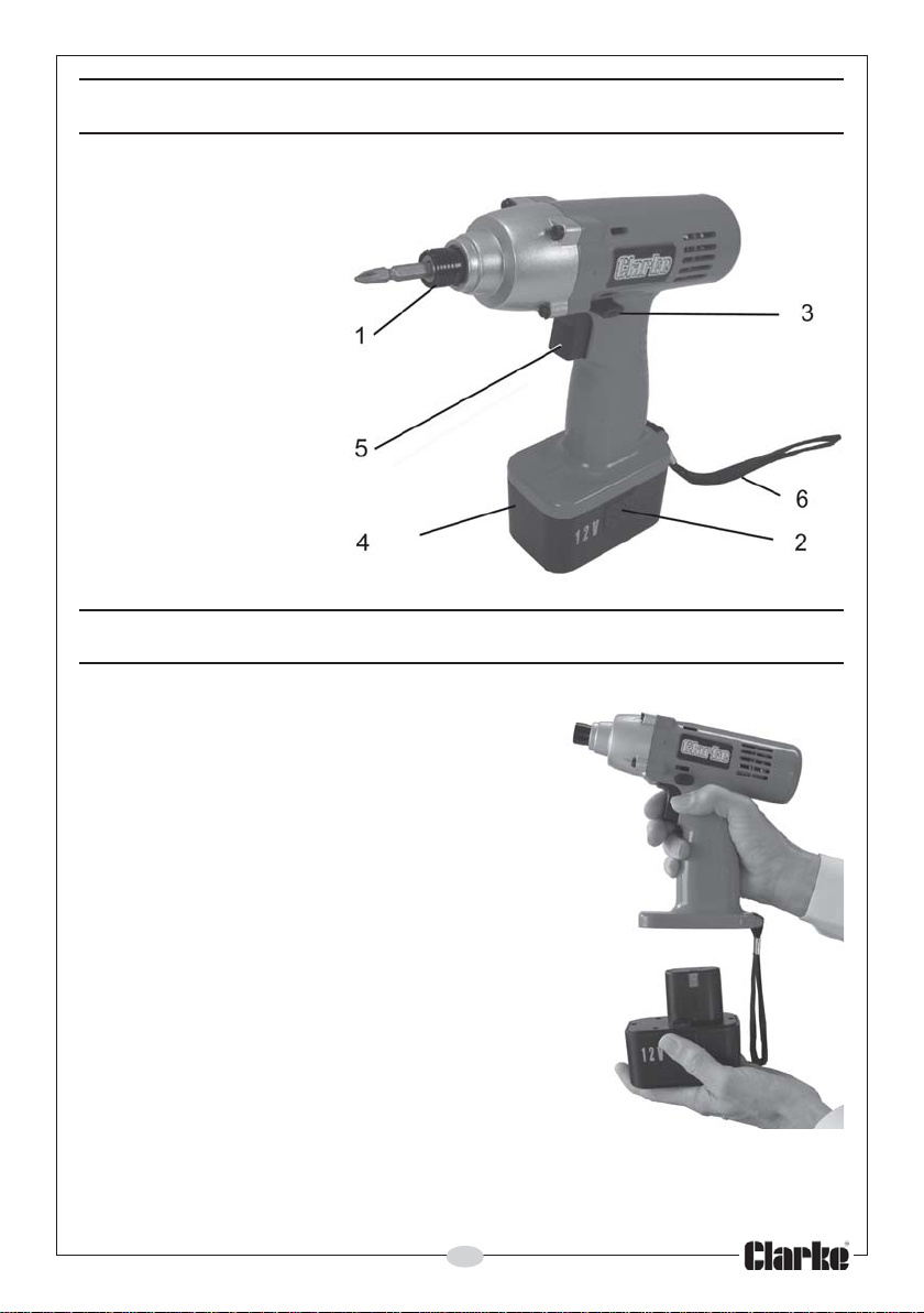
COMPONENT IDENTIFICATION
1. Bit Holder (chuck)
2. Battery Release Button
3. Forward/Reverse Switch-bar
4. Battery Pack
5. Trigger
6. Wrist Strap
BATTERY CHARGING
1. The new battery pack will require charging
before use.
2. Squeeze the battery release buttons on
either side of the battery pack and pull
gently down to disengage the battery pack
from the machine body as in Fig 1.
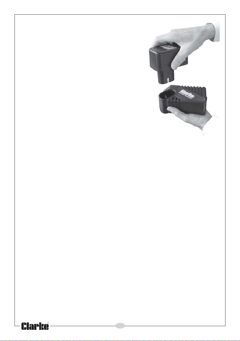
3. Insert the battery pack into the battery
charger, as shown in Fig 2, noting that it will
only fit one way.
4. Plug the charger into a 230v (mains) power
supply and switch ON.
• The green POWER ON light will illuminate
to show the unit is connected to the
mains supply. The RED charging light will
start flashing and charging will begin.
• If charging does not take place, ensure
all connections are clean and free of
grease etc.
3
6
7
9
FIG 1
7
Page 8
• If the red charging light will not stay on
for more than a few moments, the
battery pack is likely to be defective
and it must be replaced with a new
one.
• When charging is complete (typically
after about 1/2 hour), the RED
charging light stops flashing and
remains ON. The battery pack can be
considered charged and be removed,
whereupon the red light will go out. The
charging time will be dependant upon
the initial state of the batteries.
• During the charging cycle the red light
should be flashing approximately once
per second. If it flashes at a significantly
faster rate, this indicates the battery
temperature is too high. If this occurs,
the battery should be removed, allowed
FIG 2
to cool down and then re-inserted.
The above can occur either because a fully charged battery has
been inserted too quickly after being recharged, or if the battery
has become warm during use. (This is normal when the impact
wrench is used for an extended period and does not indicate a
fault condition.
• When charging a new battery pack, it may not initially accept full
charge. This is common & does not indicate a fault. It can be
recharged fully after it has been discharged a couple of times.
5. After charging, switch off and unplug the charger from the power supply.
6. Remove the battery pack from the charger and slide it back into the
machine until it clips into place. The battery pack should slide in easily. If
the battery pack is not to be fitted immediately, ensure that the metal
contacts are protected so as to avoid the possibility of a short circuit
which would cause damage.
For maximum battery life, we recommend that you maintain the battery in a
fully charged state at all times.
Remember to avoid extremes of heat or cold when charging. Avoid temperatures outside the range of Minimum 4°C /Maximum 40°C. Avoid placing
batteries in direct strong sunlight or any other heat source.
NOTE:
Ni-Cad batteries should be given a full charge when first supplied new.
Maximum battery performance will be achieved after approximately 5
complete charge/discharge cycles.
8
Page 9
The battery should be fully discharged before recharging in order to achieve
its optimum performance.
charge has been used will, in effect, reduce its capacity.
Nickel cadmium batteries will slowly lose their power whilst in storage. If they
become fully discharged, no not leave the batteries in this state for any
length of time.
Constant topping up after only a small amount of
INSTALLING & REMOVING THE BIT
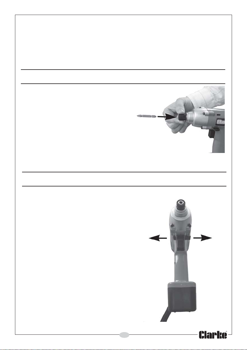
1. Pull the sleeve away from the
machine body and insert the bit into
the sleeve as far as it will go. Release
the sleeve to secure the bit in place
as shown in Fig 3.
2. To remove the bit, pull the sleeve and
draw the bit out.
• If the bit is not inserted deep enough
into the sleeve, the sleeve will not
spring back and the bit will not be
secured.
FIG 3
OPERATION
1. Squeeze the trigger to start the
machine.
2. Increase the speed of the machine by
increasing pressure on the trigger.
3. Release the trigger to stop.
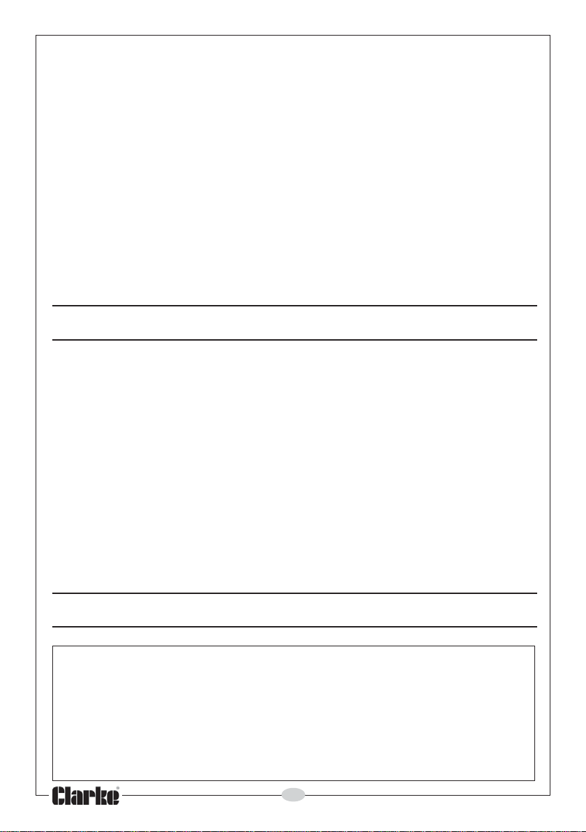
4. To run the impact screwdriver in reverse,
push the switch bar through the drive
unit as shown in Fig 4. The direction of
rotation is shown on the end face of the
bar.
• The 3-position switch bar controls
forward or reverse direction of rotation.
Select the appropriate setting ONLY
when the chuck is STATIONARY. Do not
move the switch-bar when the chuck is
moving. When the switch-bar is in the
central position the trigger is locked.
5. Always check the direction of rotation
before operation.
9
FIG 4
Page 10
6. Hold the machine firmly and place the point of the screwdriver bit in the
screw head. Apply sufficient pressure that the bit will not slip off the screw
and start the machine.
Note: Take care to use the correct bit for the head of screw that you wish to
use. Take care to point the machine straight at the screw.
7. Before starting work, always perform a test operation to determine the
appropriate tightening effort for the screw in whatever material is being
used.
8. Turn off the machine as soon as the impact sound is heard, taking care
not to damage the screw. Extra care is needed with small screws.
Note: As the battery becomes discharged, the power available will drop.
Operating the machine at low speed will cause a reduction in torque.
9. After use, recharge the battery cartridge as shown on pages 7-8. Avoid
leaving your batteries in a discharged state.
MAINTENANCE
Keep the unit clean by wiping with a dry cloth. DO NOT use solvents as a
cleaning agent.
Keep the battery pack well charged at all times.
Check the battery charger power cable to ensure it is sound & free from
cracks etc.
All bearings in this tool are lubricated with sufficient amount of high quality
lubricant for the tool’s lifetime under normal operating conditions, therefore
no further lubrication is required.
Refer to your Clarke dealer if internal maintenance is required.
Your Clarke Impact Screwdriver has been designed to give long and trouble
free service. If, however, having followed the instructions in this booklet
carefully you encounter problems, take the unit to your local Clarke dealer.
SPARE PARTS & SERVICE CONTACTS
For parts & servicing, please contact your nearest dealer, or
CLARKE International, on one of the following numbers.
PARTS & SERVICE TEL: 020 8988 7400
PARTS & SERVICE FAX: 020 8558 3622
or e-mail as follows:
PARTS: [email protected]
SERVICE: [email protected]
10
Page 11
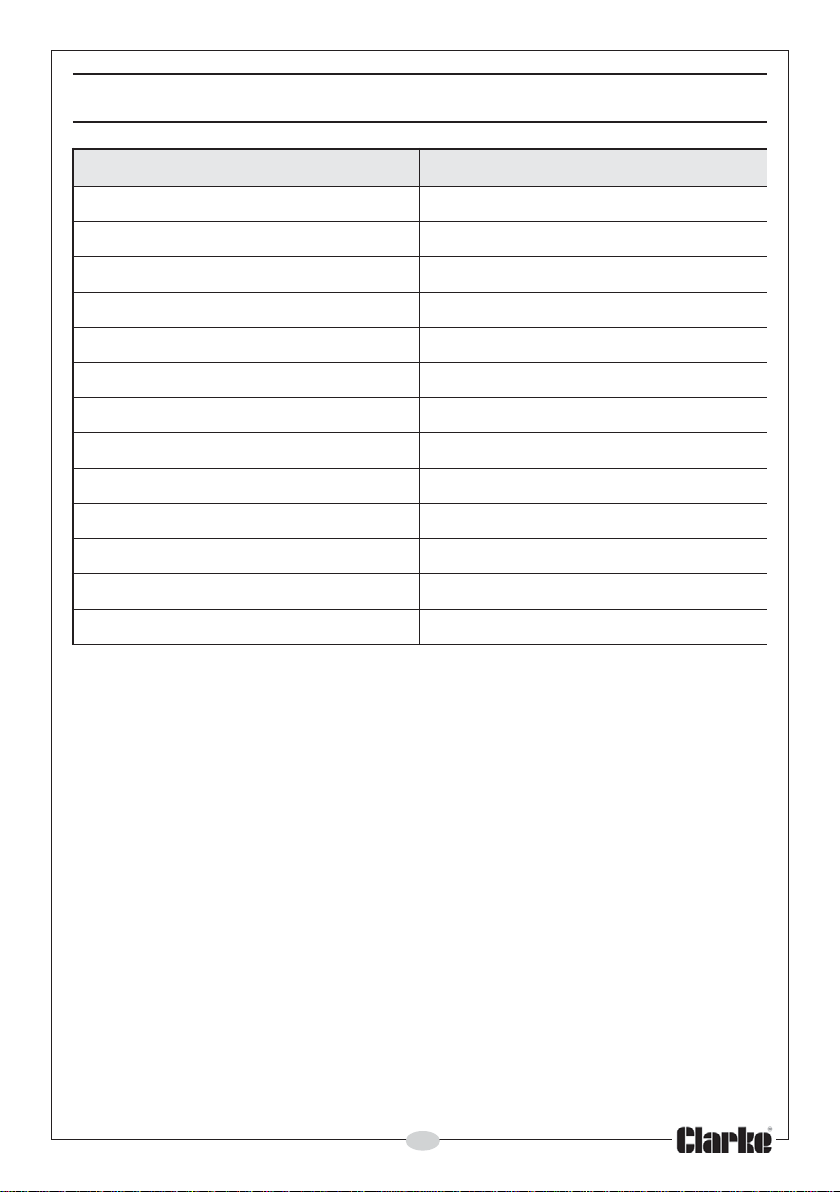
TECHNICAL SPECIFICATION
erutaeF noitacificepS
)egdirtracyrettabgnidulcni(thgieWgk80.2
mm)hxwxl(snoisnemiD832x26x002
)MPR(deepsdaol-oN0022-0
euqrotgninethgitxaMmN801
etunimrepstcapmI0092-0
egatlovtupnIzH05/V032
egatlovtuptuOA5.2/V41-CD
epytyrettaBmuim
yticapackcapyrettaBha7.1
)pL(levelrewopdnuoS)A(Bd47
)wL(derusaemlevelrewopdnuoS)A(Bd58
levelrewopdnuoS)A(Bd58<
levelnoitarbiVs/m5.2<
deetnaraug
daC-lekciN
2
Please note that the details and specifications contained herein, are correct
at the time of going to print. However, CLARKE International reserve the right
to change specifications at any time without prior notice.
11
Page 12
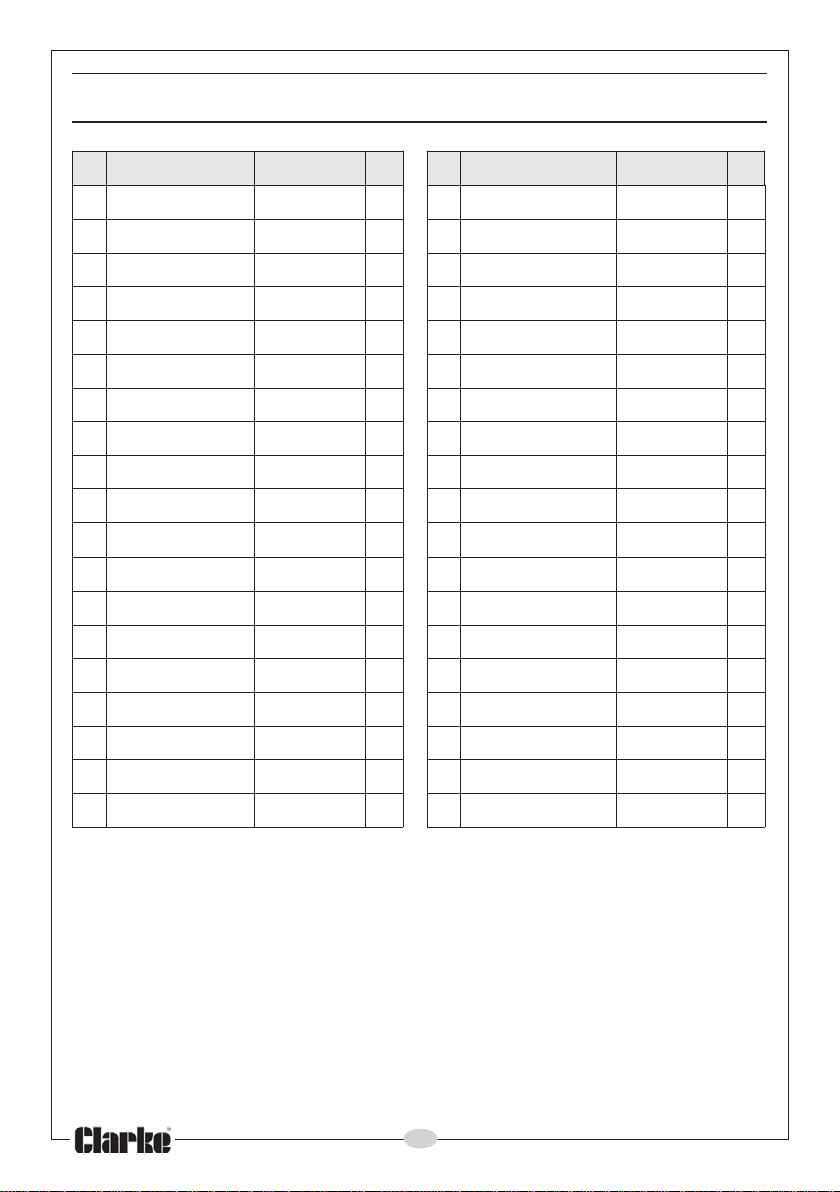
PARTS LIST
oN noitpircseD oNtraP ytQ oN noitpircseD oNtraP ytQ
1gniReiT10001SICZC191eldnipS91001SICZC1
2laeS20001SICZC102toggipS02001SICZC2
3gnirpS30001SICZC112raeGyratenalP12001SICZC2
4eve
5wercS50001SICZC432tekcarByratenalP32001SICZC1
6gnisuoHesoN60001SICZC142gniraeB42
7hsuBdrawroF70001SICZC152gnisuoHraeG52001SICZC1
8gniRerbiF80001SICZC162raeGrotoM62001SICZC1
9teksaGrebbuR90001S
01teksaG01001SICZC182rotoM82001SICZC1
11llaBleetS11001SICZC192rabhctiwS92001SICZC1
elSgnikcoL40001SICZC122teksaG22001SICZC1
001SICZC1
ICZC172wercS72001SICZC1
21livnA21001SICZC103h
31llaBleetS31001SICZC213kcaPyrettaB13001SICZC1
41teksaG41001SICZC123)HL(gnisuoH23001SICZC1
51gnirpS51001S
61teksaG61001SICZC143tneV43001SICZC1
71gnirpS71001SICZC153)HR(gnisuoH53001SICZC1
81teksaG81001SIC
ICZC133dnabtsirW33001SICZC1
ZC163wercS63001SICZC6
12
ctiwS03001SICZC1
73regrahCyrettaB73001SICZC1
Page 13
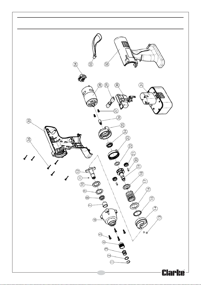
PARTS DIAGRAM
13
Page 14
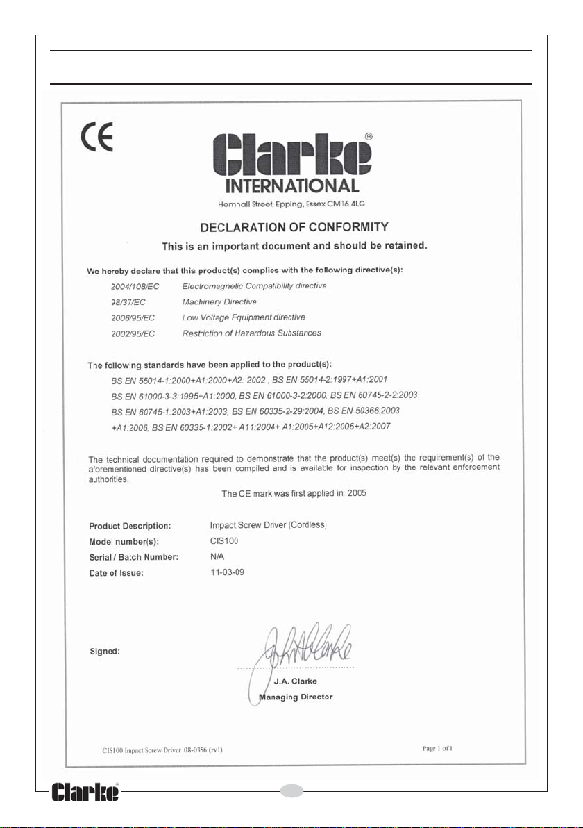
DECLARATION OF CONFORMITY
14
Page 15

NOTES
__________________________________________________________________________
__________________________________________________________________________
__________________________________________________________________________
__________________________________________________________________________
__________________________________________________________________________
__________________________________________________________________________
__________________________________________________________________________
__________________________________________________________________________
__________________________________________________________________________
__________________________________________________________________________
__________________________________________________________________________
__________________________________________________________________________
__________________________________________________________________________
__________________________________________________________________________
15
Page 16
 Loading...