

Page 1

DIGITAL
MULTIMETER
MODEL CDM-35
Part No.4500055
OPERATING
INSTRUCTIONS
0507
Page 2
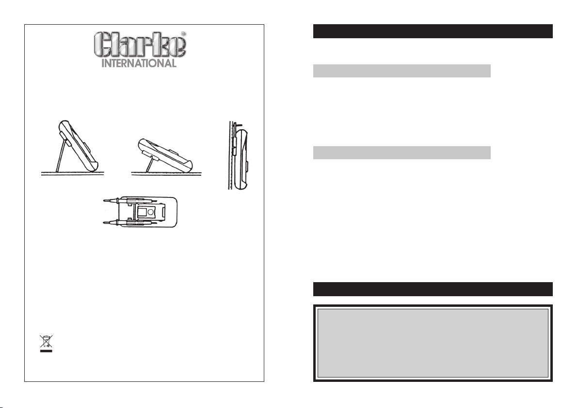
The Meter may be hung on a wall, or supported as
shown, depending upon which support is used.
The probes may be located as shown, allowing easy
one hand operation.
MAINTENANCE
Battery and/or fuse replacement should only be done after the test leads
have been disconnected.
Battery and Fuse Replacement
Note the condition of the 9-volt battery using the procedure described
above. If the battery needs to be replaced, unscrew the four screws and
remove the back cover. Replace the spent battery with one of the same
type (NEDA.1604, 6F22 or equiv). The same procedure is used to replace
the fuses. Ensure replacements are of the same size and value as the original.
Fuse 1: F 2A/250V Fuse2: F 10A/250V
Replacement Parts.
1. Test Leads (pair) Part No. HYTL060
2. Holster (Size A) Part No. HYHT60
PARTS & SERVICE CONTACTS
DO NOT dispose of this product with general household
waste. It must be disposed of according to all laws
governing waste electrical and electronic products at a
recognised disposal facility
2
For Spare Parts and Service, please contact your nearest dealer,
or CLARKE International, on one of the following numbers.
PARTS & SERVICE TEL: 020 8988 7400
or e-mail as follows:
PARTS: [email protected]
SERVICE: [email protected]
11
Page 3

Note:
1. If the resistance value being measured exceeds the maximum value of
the range selected, an over-range indication will be displayed(“1”).
Select a higher range.
For resistance of approx. 1 Megohm and above, the meter may take a
few seconds to become stable. This is normal for high resistance readings.
2.. When the input is not connected, i.e. an open circuit, the figure’1’ will be
displayed for an over-range condition.
3. When testing in-circuit resistance, ensure all power has been removed
and all capacitors are fully discharged.
4. When using the 200Megohm range, the display is 10 counts. These counts
must be subtracted from the reading.... eg. when measuring a 100M
resistance, the reading will display 101.0.
The correct measuring result iis 101.0 - 1.0 = 100M
ΩΩ
Ω
ΩΩ
ΩΩ
Ω
ΩΩ
Diode Measurement
1. Connect the BLACK test lead to the COM jack and the RED test lead to the
V/Ω jack.
(Note: The polarity of the RED test lead is “+”).
2. Set the FUNCTION switch to the position and connect the test
leads across the diode under test, red lead to the anode, black to the
cathode. Display shows the approx. forward voltage drop of the diode.
Continuity Test.
1. Connect the BLACK test lead to the COM jack and the RED test lead to the
V/Ω jack.
(Note: The polarity of the RED test lead is “+”).
2. Set the FUNCTION switch to the position and Connect the test
leads to two points of circuit, if the resistance is lower than approx. 70Ω,
the buzzer sounds.
Transistor hFE Test
1. Set the FUNCTION switch to the hFE range.
2. Determine whether the transistor is NPN or PNP and locate the Emitter,
Base and Collector leads. Insert the leads into the proper holes in the
socket on the front panel.
3. Display will read approx. hFE value at the test condition/Base Current
10µA VCE 3.2V
10
INTRODUCTION
Thank you for purchasing this Clarke Multi-Range Digital Multimeter.
This instrument is a compact, rugged, battery operated hand held 3½ digit,
digital multimeter. It is designed to measure AC and DC voltage, AC and
DC current, Resistance, Diode, Capacitance and for testing Transistors, and
Continuity.
The dual-slope A-D converter uses C-MOS technology for auto zeroing,
polarity selection and over-range indication.
It is an ideal instrument for use in the field, laboratories, workshops, and for
hobby and home applications.
GUARANTEE
This product is guaranteed against faults in manufacture for 12 months from
purchase date. Please keep your receipt as proof of purchase.
This guarantee is invalid if the product has been abused or tampered with
in any way, or not used for the purpose for which it is intended.
The reason for return must be clearly stated.
This guarantee does not affect your statutory rights.
FEATURES
• Push button ON/OFF power switch.
• Auto Power OFF
• Single 32 position rotary switch for FUNCTION and RANGE selection.
• High sensitivity of 100µV
• Auto over-range indication, with “1” being displayed on the LCD.
• Automatic reverse polarity indication on DC ranges.
• All ranges (except 10A current ranges) fully protected.
• DC Voltage measurement 200mV to 1,000V
• AC Voltage measurement 200mV to 700V rms
• DC current measurement 20µA to 10A
• AC current measurement 200µA to 10A rms
• Resistance measurement 200Ω to 200MΩ
• Diode testing with 1mA fixed current.
• Transistor hFE test with 10µA
• Holster with 2 position stand, and test lead holders to ease the taking
of readings whilst holding the meter.
3
Page 4

SAFETY PRECAUTIONS
Read this information before using the meter, taking special care regarding
any WARNING or IMPORTANT notices. The following safe practices and proper
operating procedures should be followed when using any multimeter:
• Inspect the test leads for insulation damage or exposed metal.
Damaged leads should be replaced.
• Select the proper function and range tor your measurement.
• Avoid severe shocks and do not drop the multimeter.
• Do not allow the meter to be used if it is damaged or if its safety is impaired
• WARNING: To AVOID ELECTRIC SHOCK, USE CAUTION WHEN WORKING
ABOVE 40V DC OR 25V AC RMS. SUCH VOLTAGES POSE A SHOCK HAZARD.
• Electrically disconnect the live, or hot test lead before disconnecting
the common test lead.
• Follow all equipment safety procedures. Disconnect the input power
and discharge all high-voltage capacitors through a protective
impedance before testing in Ω and with the multimeter.
• Avoid working alone.
• When making a current measurement, turn the power off before
connecting the multimeter in the circuit. Overloading a current shunt
will cause excessive heat.
• When measuring transformer secondary or motor winding current, check
the multimeter fuses first.
• When testing circuits take extra care not to touch any bare metal
including the ends of the test probes.
• The use of makeshift fuses and the short-circuiting of fuse holders is prohibited.
• Whenever it is likely that the protection has been impaired, the meter shall
be made inoperative and be secured against any unintended operation.
• Never attempt to measure a voltage or current higher than the maximum
rating of the meter.
• Never perform resistance measurements on a live circuit.
4
DC Current Measurement
WARNING, Do not attempt to measure a current in excess of 10 Amps
1. Connect the BLACK test lead to the COM jack and the RED test lead to
the mA jack for a maximum of 2A. For inputs greater than 10A, move
the red test lead to the 10A jack.
2. Set the FUNCTION switch to the A --- range to be used and connect the
test leads in series with the load under measurement. Reverse polarity is
indicated by a “—” sign being displayed in front of the reading.
Note:
1. If the current range is not known beforehand, set the FUNCTION switch
to a high range and work down.
2. When only the figure “1” is displayed over range is being indicated and the
FUNCTION switch must be set to a higher range.
3. The maximum input current is 2A, or 10A depending on the jack used.
Excessive current will blow the fuse which must be replaced. The 10A
range is not protected by a fuse. The fuse rating should be 2A and
no more to prevent damage to the internal circuitry. The maximum
terminal voltage drop is 200mV.
AC Current measurement
WARNING, Do not attempt to measure a current in excess of 10 Amps
1. Connect the BLACK test lead to the COM jack and the RED test lead to
the mA jack for a maximum of 2A. For a maximum of 10A, move the
RED test lead to the 10A jack.
2. Set the FUNCTION switch to the A~ range to be used and connect the
test lead in series with the load to be measured.
Note: See DC Current Note 1 - 3
Resistance Measurement
IMPORTANT. When checking in-circuit resistance, ensure the circuit under test
has all power removed and that all capacitors are fully discharged.
1. Connect the BLACK test lead to the COM jack and the RED test lead to
the V/Ω jack. Note
2. Set the FUNCTION switch to the range to be used and connect the test
leads across the resistance to be measured.
: the polarity of the RED test lead is “+”.
9
Page 5

OPERATION
1. Check the 9-volt battery by setting the ON-OFF switch to ON, if the
battery is weak, a + - sign will appear on the display. If this does not
appear on the display, proceed as below. See MAINTENANCE if the
battery has to be replaced.
2. The mark, or symbol, next to the test lead jacks, is a warning that the
input voltage or current should not exceed the indicated values, to
prevent damage to internal circuitry.
3. The function switch should be set to the range which you want to test
before operation.
DC Voltage Measurement
WARNING. Use extreme caution measuring high voltages, and do not
attempt to measure voltages greater than 1000 Volts, as this can
damage internal circuitry.
1. Connect the BLACK test lead to the COM jack and the RED test lead to
the V/Ω jack.
2. Set FUNCTION switch to V --- range to be used and connect test leads
across source or load. Reverse polarity is indicated by a “—” sign being
displayed in front of the reading.
Note:
1. If voltage range is not known beforehand, set the FUNCTION switch to a
high range and work down.
2. When only the figure “1” is displayed, over-range is being indicated,
and the FUNCTION switch must be set to a higher range.
AC Voltage Measurement
WARNING. Use extreme caution measuring high voltages, and do not
attempt to measure voltages greater than 700 Volts RMS, as this can
damage internal circuitry.
1. Connect the BLACK test lead to the COM jack and the RED test lead to
the V/Ω jack.
2. Set the FUNCTION switch to the V~ range to be used and connect the
test leads across the source or load under measurement.
Notes: See DC Voltage measurement Note 1.2.
8
SPECIFICATIONS
Accuracies are ± (% reading ± the number indicated inh the
respective chart, added or dxceducted from the digit, or right
DC Voltage
Input Impedance: 10M ohms on all ranges.
Overload Protection: 220V RMS on 200mV range and 1000V DCor
AC Voltage
Input Impedance: 10M ohms on all ranges.
Frequency Range: 40Hz to 400 Hz
Overload Protection: 700V RMS or 1000V peak continuous on
hand column of the reading)
Range Accuracy Resolution
200mV
2V
20V
200V
1000V
Range Accuracy Resolution
200mV
200V
700V
±0.5% of rdg ± 1 digit
± 0.8 of rdg ± 2 digit
±1.2% of rdg ± 3 digits
2V
20V
±0.8% of rdg ± 3 digits
±1.2% of rdg ± 3 digits
AC ranges, except 200mV AC range
(15 sec. max. above 300V RMS).
peak AC all others
5
100µV
1mV
10mV
100mV
1V
100µA
1mV
10mV
100mV
1V
Page 6
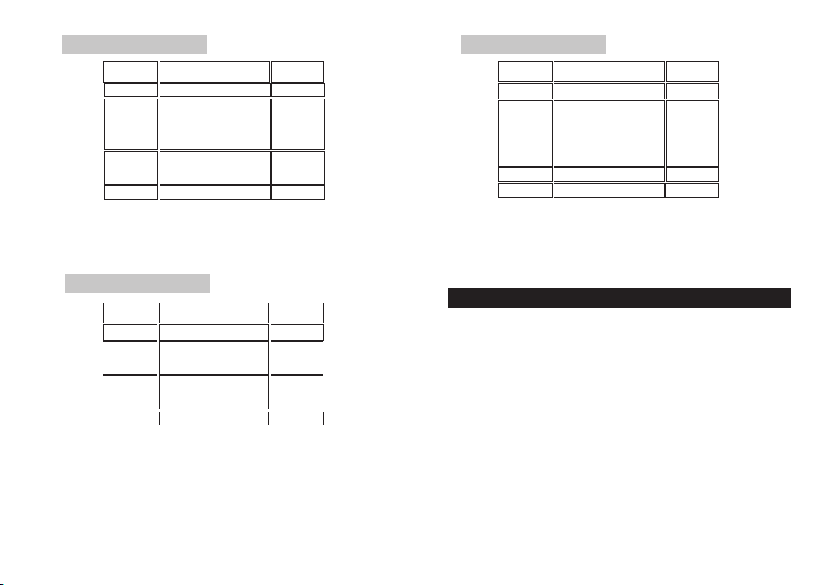
DC Current
Resistance
Range Accuracy Resolution
20µA
200µA
2mA
20mA
200mA
2A
10A
Overload Protection: 2A/250V fuse for 20µA to 2A ranges
10A/250V fuse for 10A range
Max. Input Current: 10A
±2% of rdg ± 5 digits 0.01µA
0.1µA
±0.8% of rdg ± 1 digit
±1.2% of rdg ± 1 digit
±2% of rdg ± 5 digits
1µA
10 µA
100µ A
1mA
10mA
AC Current
Range Accuracy Resolution
200µA
2mA
20mA
200mA
10A
Overload Protection: 2A/250V fuse for 20µA to 2A ranges
Frequency Range: 40Hz to 400Hz.
Max. Input Current: 10A
Indication: Average. (RMS of sine wave)
±1.8% of rdg ± 3 digits
±1.0% of rdg ± 3 digits
±1.8% of rdg ± 3 digits
2A
±3% of rdg ± 7 digits
10A/250V fuse for 10A range
6
0.1µA
1µ A
10 µA
100µ A
1mA
10mA
Range Accuracy Resolution
200Ω
2KΩ
20KΩ
200KΩ
2MΩ
20MΩ
200MΩ
Overload Protection: 220V DC/RMS. AC on all ranges
Open Circuit Voltage: Lower than 700mV
±0.8% of rdg ± 3 digits
±0.8% of rdg ± 1 digit
± 1% of rdg ± 2 digits
±5% of rdg-10 dig ±10 dig
0.1Ω
1 Ω
10Ω
100Ω
1KΩ
10KΩ
100KΩ
GENERAL CHARACTERISTICS
Maximum Display :1999 counts (3½ digits) with auto polarity
Measuring Method : Dual-Slope integration A-D convertor system.
Overrange Indication : Figure “1” displayed on the LCD.
Max. common mode voltage : 500V dc/ac rms.
Temp. for guaranteed accuracy : 23
Temperature Ranges : Operating 0OC to 40OC, 32OF to 104OF.
Power Supply : 1x 9V battery (NEDA 1604, 6F22 type or equiv).
Low Battery Indication :
Dimensions incl. Holster : 201L x 100W x 55H mm.
Weight : 478g (incl. 9 volt battery & holster).
Accessories : Operating manual, set of test leads. Holster,
indication and eng. unit.
O
C to ± 5OC.
: Storage-10OC to 50OC, 14OF to 122OF.
- + On left of display.
7
 Loading...