

Page 1

DIGITAL
MULTIMETER
Model No: CDM 15
OPERATING
INSTRUCTIONS
CDM15 - Page 1
0507
Page 2

When disposing of this product, do not dispose of with general
waste. It must be disposed of according to the laws governing
Waste Electrical and Electronic equipment, at a recognised
disposal facility.
CDM15 - Page 2
Page 3

INTRODUCTION
Congratulations on the purchase of your new CLARKE
compact digital multimeter.
This instrument is designed to measure AC and DC
voltages, DC current, Resistance, Diode, and to perform
continuity checks with accuracy and ease.
GUARANTEE
This product is guaranteed against faults in manufacture
for 12 months from purchase date. Keep your receipt
as proof of purchase. This guarantee is invalid if the
product has been abused or tampered with in any way,
or not used for the purpose for which it is intended. The
reason for return must be clearly stated. This guarantee
does not affect your statutory rights.
SPECIFICATIONS
Measuring Method .......... Dual integration mode
Display .............................. 3.5 digit LCD
Polarity ..............................
Sampling Rate.................. 2 - 3 times per second
Low Battery Indication ..... + - displayed on the left of LCD
Operating Temperature .. 0EC 40EC, less than 80% RH
Dimensions ....................... 70 (W) x 120 (H) x 18 (D) mm
Weight .............................. Approx 110g (Incl. batteries)
Battery .............................. 9 - 12V, GP23A or equivalent.
Accessories .......................
Auto. negative polarity indicated
Carrying case. Operating manual.
CDM15 - Page 3
Page 4
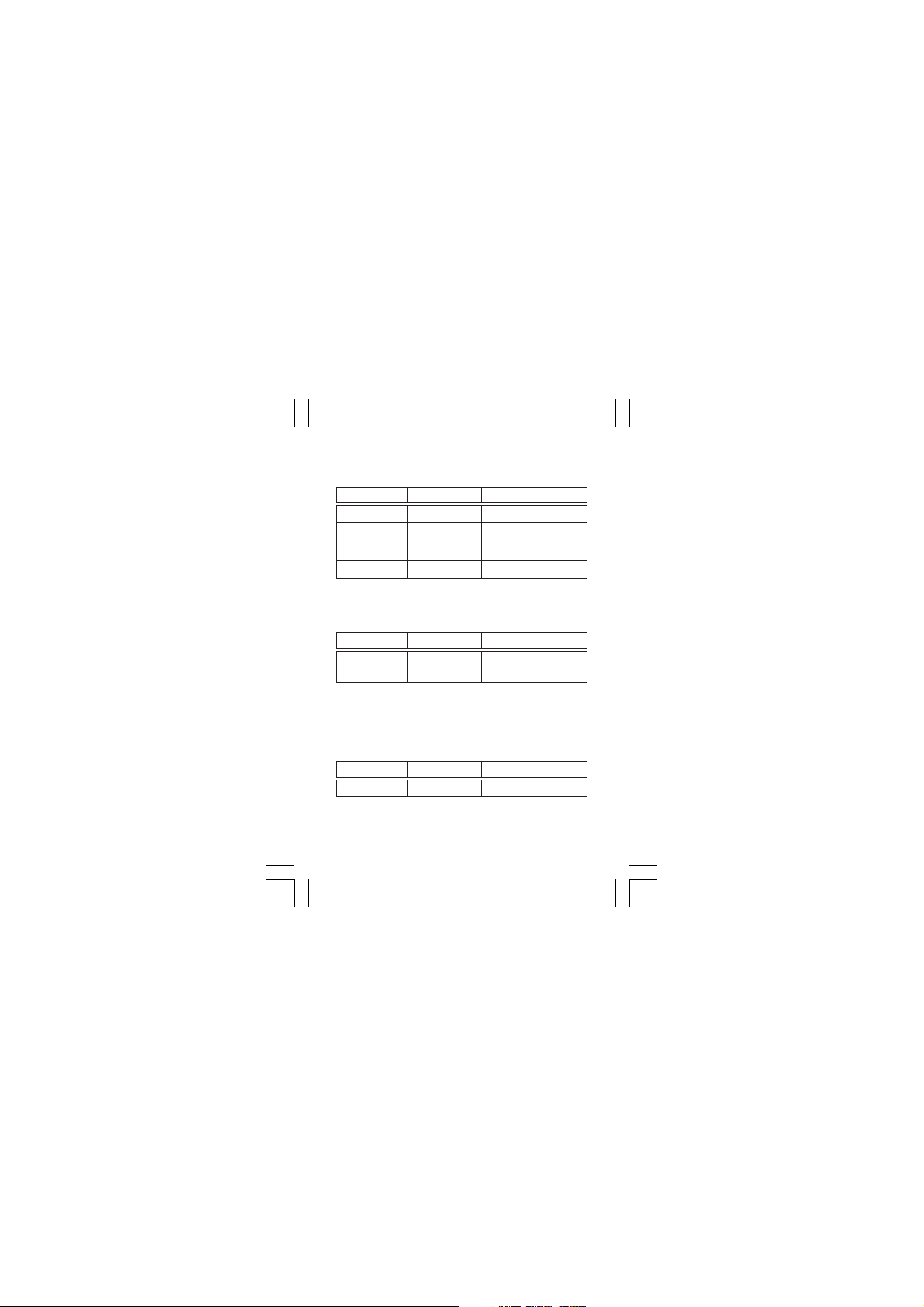
DC VOLTAGE (1 year 18ºC - 28ºC)
Range Resolution Accuracy
2V 1mV ± 0.5% of rdg ± 1 digit
20V 10mV ± 0.8% of rdg ± 1 digit
200V 0.1V ± 0.8% of rdg ± 1 digit
500V 1V ± 0.8% of rdg ± 1 digit
Maximum allowable input: 500V DC
AC VOLTAGE (1 year 18ºC 28ºC)
Range Resolution Accuracy
200V 0.1V ± 1.2% of rdg 10 digits
500V 1V ± 1.2% of rdg 10 digits
Frequency Range: 45 - 1000Hz
Maximum allowable input: 500V rms AC
Response: Ave. - rms of sine wave
DC CURRENT (1 year 18ºC 28ºC)
Range Resolution Accuracy
200mA 0.1mA ± 2.0% of rdg 2 digits
Overload Protection: 200mA/250V fuse.
CDM15 - Page 4
Page 5
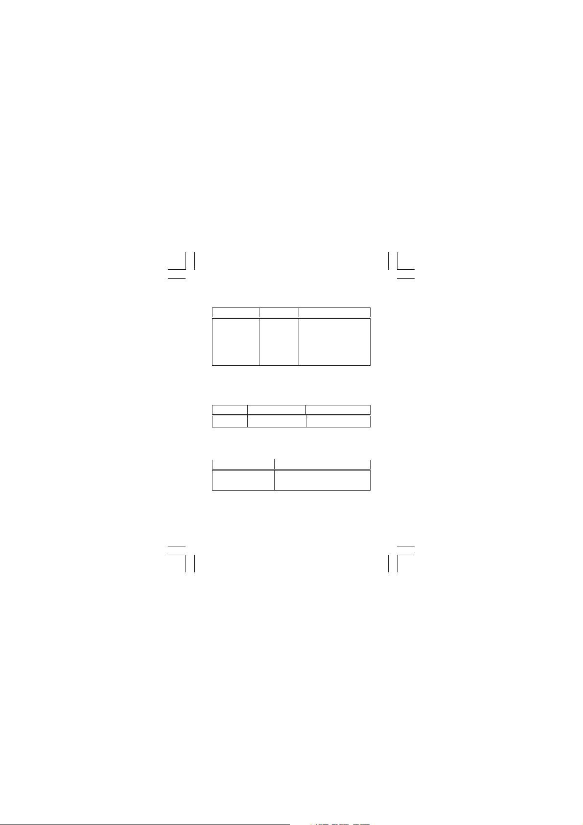
RESISTANCE (1 year 18ºC 28ºC) .
Range Resolution Accuracy
2kohm 1 ohm ±1.0% of rdg ± 2 digits
20kohm 10 ohm ±1.0% of rdg ± 1 digits
200kohm 100 ohm ±1.0% of rdg ± 1 digits
2000kohm 1 kohm ±1.0% of rdg ± 1 digits
Maximum Open Circuit Voltage: 0.65V
Overload Protection: 250V rms AC
DIODE
Resolution Test Current (Max) Open Circuit Voltage
1mV 0.8mV 3.2V
Overload Protection: 250V rms AC
AUDIBLE CONTINUITY TEST
Resolution Description
1 ohm Built in buzzer sounds when
Overload Protection: 250V rms AC
resistance is less than 50 ohms
CDM15 - Page 5
Page 6
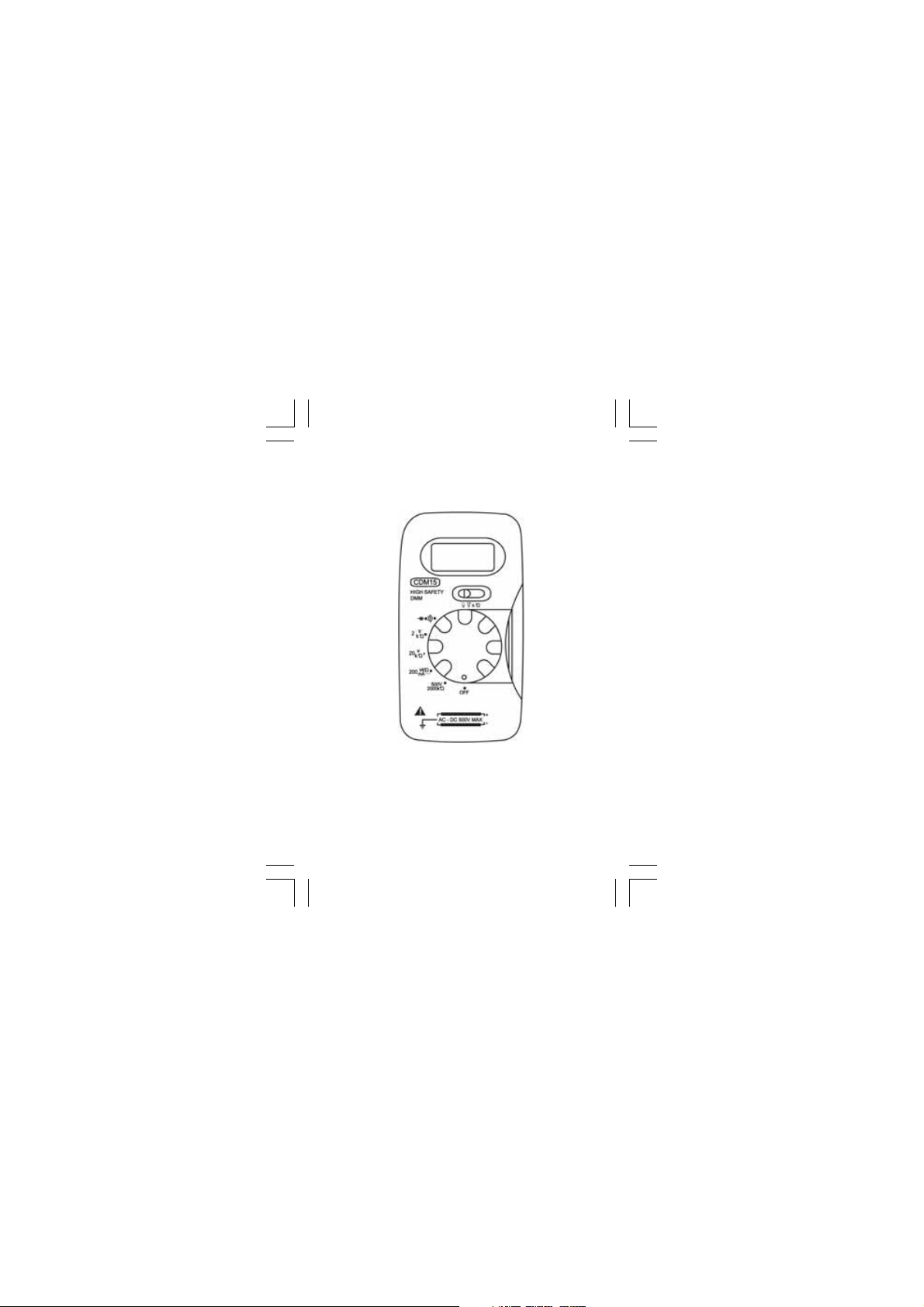
DESCRIPTION OF PANEL
1.888
1. Power Switch/Range Selector. For selecting
measurement ranges and switching Power ON
2. Function Switch. Switch for selecting functions.
3. Display 3.5 digit LCD from 0 to 1999 counts.
4. Test Leads. Red test lead for positive (+) polarity,
Black test lead for negative (-) polarity.
CDM15 - Page 6
Page 7

OPERATING INSTRUCTIONS
WARNING: Extreme care should be taken when reading
high voltages. DO NOT exceed maximum voltage for
which the meter is designed.
DC VOLTAGE MEASUREMENT
1. Set function switch to V position
2. Set range switch to desired position. If magnitude
of voltage is unknown beforehand, set the switch
to its highest range and then reduce until
satisfactory reading is obtained.
3. Connect test leads across the source or load under
measurement. The polarity of the RED lead
connection will be indicated as well as the voltage.
4. When the range switch is set to the 500V position, “HV”
will appear on the display, to remind you of a high
voltage measurement. Special care should be taken.
AC VOLTAGE MEASUREMENT
1. Set function switch to V position.
2. Set range switch to desired position. Measurement
reading can be obtained at 2V and 20V positions,
but accuracy is not guaranteed.
3. Connect test leads across load or source under
measurement. Read voltage value on display.
4. When the range switch is set to the 500V position, “HV”
will appear on the display, to remind you of a high
voltage measurement. Special care should be taken.
~
CDM15 - Page 7
Page 8

DC CURRENT MEASUREMENT
1. Set function switch to A position.
2. Set range switch to 200 mA position. Readings can
be taken from other positions, but the decimal
point will not be in correct position.
3. Open circuit to be measured, and connect leads
in series with the load in which current is to be
measured.
4. Read current value on display, along with the
polarity.
RESISTANCE MEASUREMENT
WARNING: If resistor to be measured is connected to
a circuit, ensure all power to the circuit is OFF, and all
capacitors are fully discharged before attaching test
leads.
1. Set function switch to Ω position.
2. Set range switch to desired position.
3. Connect test leads across resistor to be measured,
and read resistance value on display.
CDM15 - Page 8
Page 9

DIODE & CONTINUITY TEST
1. Set function switch to Ω position.
2. Set range switch to ( ) position.
3. Connect the red lead to the anode of the diode to be
measured, and the black lead to the cathode. Read
the forward voltage drop on the display in mV. If the
leads are reversed, the figure “1” will be displayed.
4. Connect the test leads to two points of a circuit.
The buzzer will sound if the resistance is lower
than 50 ohms.
MAINTENANCE
CAUTION.
1. Do not operate the instrument unless the back
cover is place and fastened.
2. Make sure test leads are disconnected from the test
circuit, and range switch is set to OFF before opening
case.
BATTERY REPLACEMENT
1. When batteries become exhausted, or drop below
the operating voltage, a sign will appear on
the left of LCD.
2. Turn off meter and remove test leads from all test
circuits prior to replacing batteries.
3. Remove the screw from the back cover and open
the case. Replace batteries, ensuring proper
polarity is observed.
+ -
CDM15 - Page 9
Page 10

REPLACEMENT OF FUSE
Proceed as for changing battery, ensuring the fuse
replacement is of the same size and rating as the
original. Failure to do so may result in serious damage
to your meter or possibly even fire.
(Fuse must be no more than - 200mA / 250V)
REPLACEMENT PARTS.
1. Test Leads (pair) Part No. CH1501
2. Fuse. Part No. CH1502
PARTS & SERVICE CONTACTS
For Spare Parts and Service, please contact your nearest dealer,
or CLARKE International, on one of the following numbers.
PARTS & SERVICE TEL: 020 8988 7400
PARTS & SERVICE FAX: 020 8558 3622
or e-mail as follows:
PARTS: [email protected]
SERVICE: [email protected]
CDM15 - Page 10
Page 11
NOTES
CDM15 - Page 11
Page 12
CDM15 - Page 12
 Loading...