

Page 1
SAFETY PRECAUTIONS
1 To avoid electrical shock and/or damage to the instrument,
do not measure voltages that exceed 600V above ground.
2. Before use, ALWAYS inspect the test leads, connectors and
prods for cracks, breaks or crazes in the insulation. If in doubt
do not use. Renew the parts as necessary.
3. Never exceed the protection limit indicated in the
specifications for each range of measurement.
4. Never perform resistance measurements on live circuits.
5. Before inserting transistors for testing, ensure that test leads
have been disconnected from any measurement circuits.
DC VOLTAGE MEASUREMENT
1. Connect RED test lead to “V
2. Set range selector switch to desired DC V position. If the value
to be measured is unknown, set the selector to the
highest range, and reduce until satisfactory reading is realised.
3. Connect test leads to device or circuit to be measured.
4. Turn power, to device being measured-ON. The voltage value
will be displayed on the digital display along with the polarity.
ΩΩ
ΩmA” socket and BLACK to COM
ΩΩ
DC CURRENT MEASUREMENT
1. Connect RED lead to “V
up to 200mAmps, and the BLACK lead to COM.
For measurements between 200mA and 10 Amps, connect
RED lead to 10A input socket ensuring it is fully depressed.
2. Set range selector switch to desired DC A position.
3. Open the circuit to be measured and turn ON the power.
4. Connect the leads across the load, i.e. in series with the
load to be measured.
5. Read the current value on the digital display.
ΩΩ
ΩmA” input socket for measurements
ΩΩ
AC VOLTAGE MEASUREMENTS
1.
Connect RED lead to
2. Set range selector switch to desired AC A position.
3. Connect test leads to device or circuit to be measured.
4. Turn power, to device being measured -ON. The voltage value
will be displayed on the digital display along with the polarity.
ee
“V
emA”
socket and BLACK lead to COM.
ee
RESISTANCE MEASUREMENTS
1. Connect RED lead to “V
BLACK lead to COM.
2. Set range selector switch to desired W position.
3. IMPORTANT: If the resistance to be measured is
connected to a circuit, turn OFF the power and
discharge ALL capacitors before applying the test prods.
4. Connect the test leads and read resistance value on
the digital display
ΩΩ
ΩmA” input socket and the
ΩΩ
hFE MEASUREMENT
1. Insert E, B and C pins of transistor to the corresponding
slots in the hFE socket, paying special attention as to its
type - NPN or PNP.
2. Read the hFE value on the digital display.
DIODE TESTING
1. Connect RED test lead to “V
BLACK to COM
2. Set the rotary switch to the position.
3. Connect the RED test leads to the anode of the diode
and the BLACK lead to the cathode.
4. The approx. forward voltage drop will be displayed on
the LCD in mV. It the polarity is reversed, Fig. “1” will be
displayed.
ΩΩ
ΩmA” input socket and
ΩΩ
BATTERY AND FUSE REPLACEMENT
Before opening the back cover, ensure the test leads are
disconnected from any energised circuits to avoid the
It “BAT” appears on the LCD, this indicates that the battery
needs replacing. The fuse should rarely need replacement,
and a blown fuse is almost always as a result of operator error.
1. Remove the two phillips screws from the back of the
unit, and carefully withdraw the back cover.
2. Carefully pull out the blown fuse and replace with one
of the same value - 0.8Amp 250V Fast Blow.
3. Replace the battery with one of the same value- 9V
alkaline or carbon-zinc battery (NEDA16O4), being
careful to observe polarity
CAUTION
possibility of electric shock.
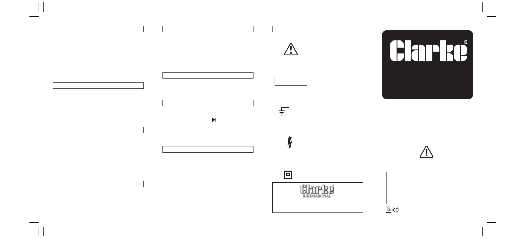
SAFETY SYMBOLS
This marking adjacent to another
marking or terminal or operating
device indicates that the
operator must refer to an
explanation in the Operating
Instructions to avoid damage to
the equipment and/or to avoid
personal injury.
This warning sign denotes a
hazard, It calls attention to a
WARNING
600Vmax
For Spare Parts and Servicing, please contact your nearest dealer, for
CLARKE International on the following number:
procedure, practice or the like,
which, it not correctly performed
or adhered to, could result in
personal injury.
This marking advises the user that
the terminals so marked must not
be connected to a circuit point
at which the voltage, with
respect to earth ground,
exceeds, in this case, 600V.
This symbol adjacent to one or
more terminals, identifies them as
being associated with ranges
that may, in normal use, be
subjected to particularly
hazardous voltages. For
maximum safety, the instrument
and the test leads should not be
handled when these terminals
are energised.
This symbol indicates that the
instrument complies with all
requirements for double
insulation.
020 8988 7400
DIGITAL MULTIMETER
Model No: CDM10A
Part Nio: 45800005
Operating Instructions
Before using this instrument, you should read and
fully understand this instruction leaflet.
Failure to understand and comply with the
warnings and operating instructions can result in
serious or even fatal injury and/or damage to
property.
0507
Page 2
DO NOT dispose of this product with general household waste. It
must be disposed of according to all laws governing waste
electrical and electronic products at a recognised disposal facility
Thank you for purchasing this Clarke Multi-Range Digital
Multimeter.
This instrument is a compact, rugged, battery operated hand
held 3½ digit, digital multimeter. It is designed to measure
AC and DC voltage, DC current, Resistance, Diode, and
Transistor testing.
It is an ideal instrument for use in the field, laboratories, workshops,
and for hobby and home applications.
GUARANTEE
This product is guaranteed against faults in manufacture for
12 months from purchase date.
Your receipt will be required as proof of purchase.
This guarantee is invalid it the product has been abused or
tampered with in any way, or not used for the purpose for
which it is intended. The reason for return must be clearly
stated.
This guarantee does not affect your statutory rights.
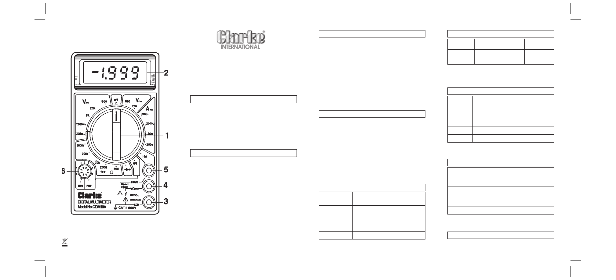
FRONT PANEL
1. Rotary Function and Range switch.
Selects the function and range as well as having an OFF
position.
Always remember to switch the instrument OFF when not
in use to prolong battery life.
2. Display
3 ½ Digit, 7 segment, 1/2" high LCD
3. COM (Common) or Earth Socket
Plug in connection for BLACK (negative) test lead
ΩΩ
4. “V
ΩmA”Socket
ΩΩ
Plug in connection for RED (positive) test lead for all
measurements except 10 Amp range.
5. 10 Amp Socket
Plug in connection for RED test lead for 10 Amp measurement
6. hFE Socket
For measuring transistor hFE
FEATURES
• Single 20 pos’n rotary switch for FUNCTION and RANGE selection.
• Automatic Battery indicator with BAT” displayed on LCD
• Auto over-range indication, with “1” being displayed on LCD.
• Automatic reverse polarity indication on DC ranges.
• DC Voltage measurement 0.1µV to 600V
• AC Voltage measurement l00mV to 750V RMS
• DC Current measurement 0.1µA to 10A
• Resistance measurement 0.1Ω to 2MΩ
• Diode testing with 1.5mA Fixed current.
• Transistor hFE test with 10A base current.
SPECIFICATIONS
Display: 3½ Digit, 7 segment, 1/2" high LCD with polarity
Over Range Indication: Fig. “1” displayed on LCD
Max. Common Mode Voltage: 600V peak
Operating Environment: 0 to 40ºC. (32 to 104º F)
Storage Environment: -10C to 50ºC (10 to 112 ºF)
Power Supply: 9V alkaline or carbon-zinc battery (NEDA16O4)
Fuse Type: 250mAmp 250V. Fast blow.
Dimensions: 126x70x25mm (LxWxD)
Net Weight: 170gm (6oz)
DC VOLTAGE
RANGE ACCURACY RESOLUTlON
200mV 100µV
2V ±0.5%±2digits 1mV
20V l0mV
200V l00mV
600V ±0.8% ± 2 digits 1V
Overload protection 250V RMS for 200mV range and 600V
DC or RMS AC for other ranges.
18 TO 28ºC
AC VOLTAGE
RANGE ACCURACY RESOLUTION
200V ±12% of Rdg ± 10 digits 100mV
600V 1V
RESPONSE: Ave. responding, calibrated in rms of sine wave
FREQUENCY RANGE: 45Hz to 450MHz
OVERLOAD PROTECTION: 600V DC or RMS AC for all ranges.
18 TO 28ºC
DC CURRENT
RANGE ACCURACY RESOLUTION
200µA l00nA
2000µA ±1.0% of Rdg ± 2 digits 1µA
20mA l0µA
200mA ±1.5% of Rdg ± 2 digits l00µA
10A ±3.0% of Rdg ± 2 digits l0mA
OVERLOAD PROTECTION: 250mA, 250V Fuse: 10A Range
unprotected
18 TO 28ºC
RESISTANCE
RANGE ACCURACY RESOLUTION
200Ω ±0.8% of Rdg ±3digits 0.1Ω
2000Ω 1 Ω
20kΩ ±0.8% of Rdg ± 2 digits 10Ω
200kΩ 100Ω
2000kΩ ±1.0% of Rdg ±2digits 1kΩ MAX.
OPEN CIRCUIT VOLTAGE: 3.2V
OVERLOAD PROTECTION: 250V RMS AC on all ranges.
18 TO 280C
DIODE TEST
Measures approx. forward voltage drop of the diode.
Overload protection: 250V RMS AC
 Loading...