

Page 1
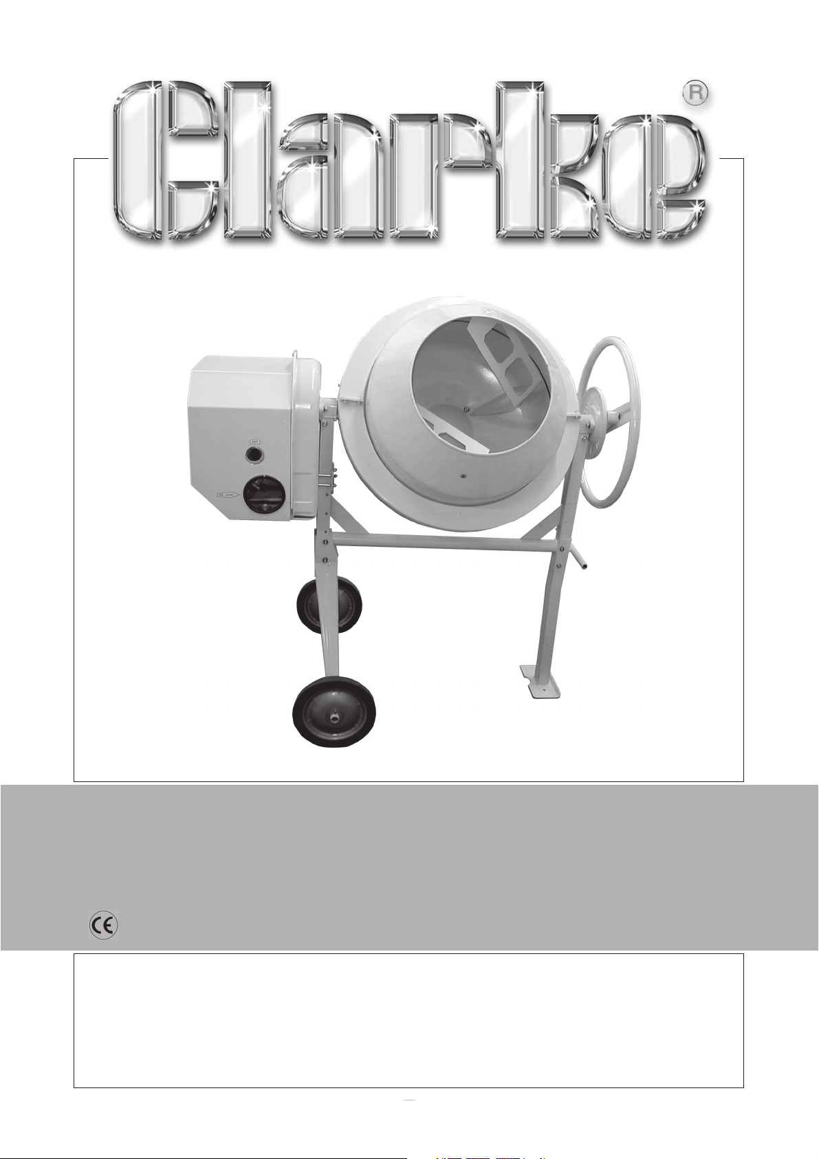
CEMENT MIXER
CEMENT MIXER
Model CCM125P
Part No. 3400820
OPERATING & MAINTENANCE
INSTRUCTIONS
o
1005
Page 2

Please read this manual in conjunction with the Engine Handbook
© Copyright CLARKE International. All rights reserved. March, 2001
o
2
Page 3
Thank you for purchasing this CLARKE Engine Driven Concrete Mixer, model CCM125P.
Please read this leaflet thoroughly and follow the instructions carefully, in doing so you will
ensure the safety of yourself and that of others around you, and you can look forward to the
mixer giving you long and satisfactory service.
GUARANTEE
This CLARKE product is guaranteed against faulty manufacture for a period of 12 months from
the date of purchase. Please keep your receipt as proof of purchase.
This guarantee is invalid if the product is found to have been abused or tampered with in any
way, or not used for the purpose for which it was intended.
Faulty goods should be returned to their place of purchase, no product can be returned to us
without prior permission.
This guarantee does not effect your statutory rights.
CONTENTS
General Safety Precautions ................................................................... 4
Unpacking & Pre-Assembly ................................................................... 5
Assembly ................................................................................................. 6
General Information ............................................................................... 11
Operation ................................................................................................ 11
Maintenance ........................................................................................... 12
Specifications .......................................................................................... 13
Parts & Service Contacts ........................................................................ 13
Parts List and Diagram ............................................................................14-15
o
3
Page 4

GENERAL SAFETY RULES
WARNING:
As with all machinery, there are certain hazards involved with their operation and use.
Exercising respect and caution will considerably lessen the risk of personal injury.
However, if normal safety precautions are overlooked or ignored, personal injury to
the operator or damage to property may result.
ALWAYS READ THE MANUAL. Become familiar with the entire operating manual. Learn the
✓
machine’s applications and limitations as well as the specific potential hazards peculiar to it.
ALWAYS CHECK FOR DAMAGED PARTS. Before use of the machine, it should be checked to
✓
ensure that it will operate properly and perform its intended function. Check for any
condition that may affect its operation. A part that is damaged should be properly repaired
or replaced before the mixer is put into use.
ALWAYS KEEP COVERS AND GUARDS IN PLACE and in good condition.
✓
ALWAYS REMOVE TOOLS etc. Form habit of checking to ensure that any tools used for adjusting/
✓
repairs, are removed from machine before use.
NEVER operate the machine whilst under the influence of DRUGS, ALCOHOL or any
✗
MEDICATION.
NEVER STAND ON THE MACHINE. Injury could occur from a fall.
✗
NEVER LEAVE MACHINE RUNNING UNATTENDED. Turn the engine OFF.
✗
NEVER put your hands inside the drum when it is rotating. Keep your hands well clear of
✗
the rotating drum at all times.
NEVER WEAR JEWELLERY or loose clothing that could be snagged by the rotating drum.
✗
DO NOT LOAD THE DRUM WHEN IT IS STATIONARY. Always start the engine and ensure the
✗
drum is rotating.
CAUTION: TAKE ALL PRECAUTIONS REGARDING THE USE OF PETROL.
•
Always
Always
•
Always
•
Never
•
Never
•
allowed to dry before attempting to start the engine.
switch the engine OFF when refuelling.
refuel away from any source of heat or naked flames.
refuel in a well ventilated area.
smoke whilst refuelling.
start the engine if there is spilled fuel. Any spillage must be wiped clean and
]
•
Always
Always
•
Always
•
Never
•
WARNING: EXHAUST FUMES CAN KILL
use in a well ventilated area.
position the exhaust outlet away from people.
keep children away from the mixer
use the mixer indoors or in a confined space.
o
4
Page 5
UNPACKING & PRE-ASSEMBLY CHECK
Remove all components from the packing cases and lay them out neatly so that they may
be identified and checked for any possible damage during transit.
Should any component be found to be damaged, please contact your Clarke dealer
immediately.
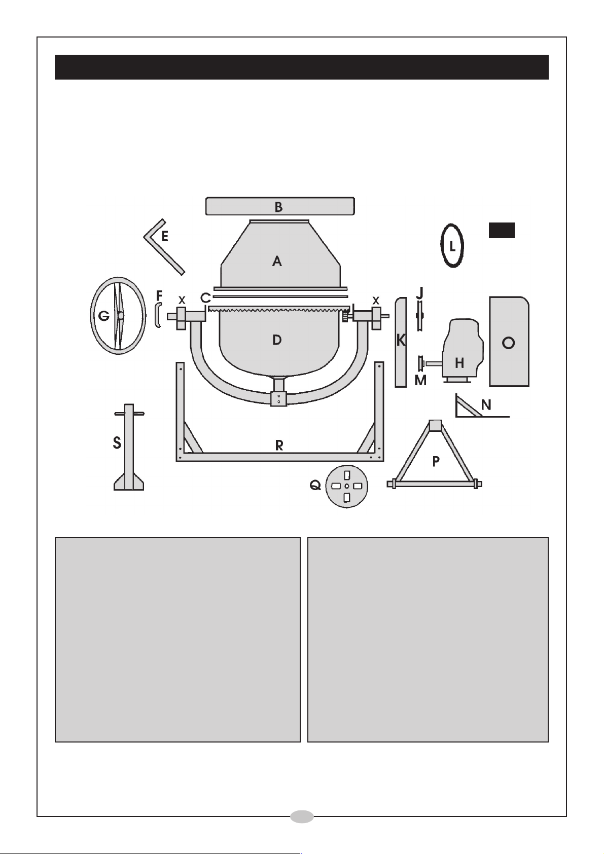
Check off the components against the following list, and referring to Fig. 1.
Fig.1
A. Upper Drum Section
B. Drum Collar (2 pcs)
C. Rubber Sealing Ring
D. Bottom Drum Assembly
E. Mixing Blades (2 pcs)
F. Locking Plate
G. Hand Wheel
H. Engine (Packed Separately)
J. Driven Pulley
K. Inner Engine Cover
L. Pulley/Drive Belt
M. Motor Pulley and Key
N. Engine Support Plate
O. Outer Engine Cover
P. Axle Assembly
Q. Wheel (2 pcs)
R Main Frame
S Leg with handle
Indicated also are the
Bearing Blocks (X)
Also included in the packing case is a 6mm x 305mm steel rod (used for pulley alignment),
and a bag containing all nuts, bolts, washers and fixings. (Please refer to the parts list on
page 15 for full list).
o
5
Page 6
ASSEMBLY
NOTE: 1. Letters in brackets refer to Fig.1
2. Unless otherwise stated, all nuts, bolts, washers and fixings are supplied.
IMPORTANT
For maximum safety and to ensure the adjustments are carried out correctly,
assistance should be employed during the assembly operation.
1. The Stand
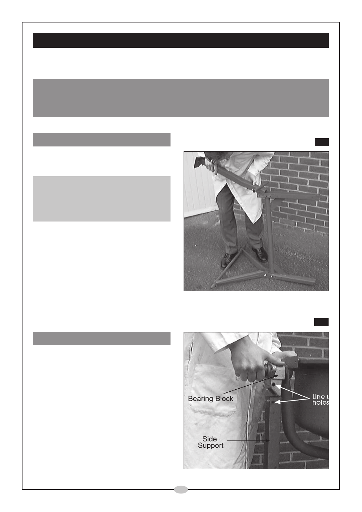
1.1 Attach the axle assembly (P) to the frame
(R), using two M8 x 60 bolts, together with
nut, spring and flat washers, ( see Fig.2).
NOTE:
A number of holes are provided to mount the
Axle assembly. Select those you feel will provide
a comfortable working height ....bearing in mind
the minimum height required to allow a
wheelbarrow to be placed beneath the drum.
1.2 Turn the frame over and attach the Leg (S),
in the same manner, as shown in Fig.2.
1.3 Slide a wheel on to each stub axle, followed
by a large flat washer and locate them using
the split pins provided.
Tighten all nuts securely before righting the
stand.
Fig.2
2. The Bottom Drum
2.1 Carefully, and with assistance, lower the
bottom drum assembly (D), on to the stand
as shown in Fig.. 3, so that the bearing blocks
(X), slot into the channels provided by the
side supports.
The drive shaft end, i.e. that end where the
pinion drives the drum, should be at the AXLE
end of the Frame.
2.2 Line up the holes in the side support with
those in the bearing block and enter an M8
x 60 bolt with flat washer and secure using a
nut and spring washer.
Fig.3
o
6
Page 7
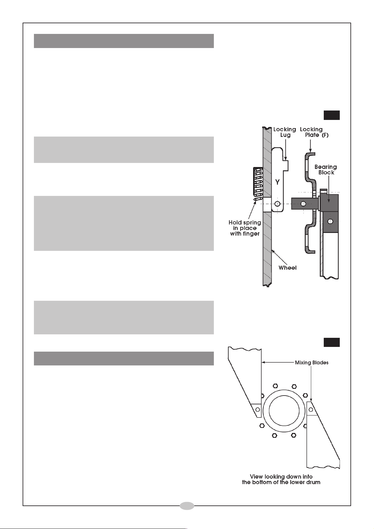
3. The Hand Wheel & Fittings
3.1 Slide the Locking Plate (F), over the large diameter shaft, at the leg end of the frame, with
the rim facing inwards, as shown in Fig.4.
(Note that the hole in the Plate is ‘notched’. This is to allow the plate to slide over the lugs
of the circlip on the shaft).
Secure with two M8 x 25 bolts, each with a nut, flat and spring washer, ensuring nuts are
tight.
3.2 Insert the spring, into its holder in the Handwheel,
and holding it in place, slide the wheel over the large
diameter shaft so that the shaft retains the spring.
NOTE:
This operation may need a little exertion in order to compress the
spring sufficient to be able to slip the handwheel on to the shaft.
3.3 Line up the holes in the bracket (Y, Fig.. 4), with the
hole drilled in the shaft, then insert the M10 x 65mm
bolt with flat washer at the bolt head.
NOTE:
You will find it an easier task to line up the holes on one side of
bracket ‘Y’ only, to begin with. Enter the bolt, then use that as
a pivot, by pushing the handwheel IN to square it up, in order
to line up the holes on the other side. When the holes at the
opposite side are aligned, tap the bolt through GENTLY to avoid
damaging the threads.
3.4 Screw on two nuts. Screw the first nut up against the
bracket firmly, but not so tightly so as to prevent the
handwheel from pivoting about the bolt. Lock the
nut in this position by screwing up the second nut,
tightly so that it locks.
Fig..4
NOTE:
The handwheel must be allowed to pivot about the bolt so
that the lugs on the bracket (Y) can be engaged or disengaged
from the slots in the Locking Plate.
4. The Mixing Blades
4.1 Bolt the blades in place loosely as shown in Fig. 5.
It is IMPORTANT that the blades are orientated
exactly as shown. This ensures that the mix will be
thrown OUTWARDS when the drum turns
Two holes are provided at the base of the drum into
which a M6 x 20 bolt may be inserted from the
outside. These bolts are provided with a flat washer
and leather washers. The leather washer should bear
against the drum. A spring washer and a nut should
be threaded on loosely on the inside. Do not tighten
the nuts.
Fig.5
o
7
Page 8
5. The Upper Drum
Note:
Before bolting down the upper drum section, it is necessary to perform a ‘dry run’ in order to determine the
correct orientation, to ensure all components are correctly aligned.
5.1. With assistance, lower the upper drum section on to the lower drum.
Rotate it until the position is found where the mixing blade upper mounting holes line up
with the corresponding square holes in the upper drum section, and the holes in the rims
of the two drum sections also become aligned.
Mark this position on the upper and lower rims with a pencil or chalk mark, then remove
the upper drum section.
5.2. Apply a film of impact adhesive (not supplied) to the rim of the drum, according to the manuf-
acturers instructions, and ensuring the rim is perfectly clean beforehand. Position the rubber seal
on to the rim so that the holes in the seal and those in the rim of the drum are aligned.
5.3. With assistance, lower the Upper Drum section on to the Lower Drum, so that the two
marks, previously made, are aligned.
Insert M6 x 16 cross headed screws into each of the
holes in the rim together with a flat washer, and secure
from below with a spring washer and nut, ensuring the
tightening process is carried out progressively.
Fig.6
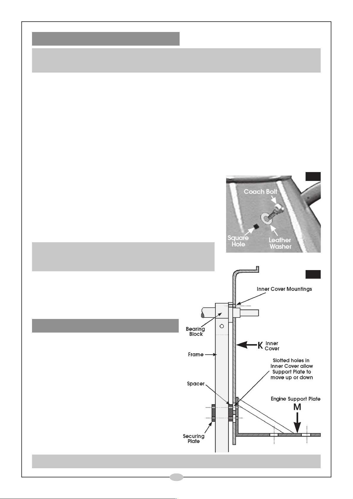
5.4. Secure the Mixing Blades to the Upper Drum by inserting
a coach bolt, with leather washer, through the square
hole in the drum. (See Fig.6).
NOTE:
The square portion of the bolt should sit snugly in the square hole in
the upper drum section, with the leather washer squeezed between
the bolt head and the drum, see Fig.. 6.
Secure the mixing blade on the inside using
a flat washer, spring washer and nut.
5.5 Finally, ensure both top and bottom Mixing
Blade mountings are tight.
6. The Engine Covers and Fittings
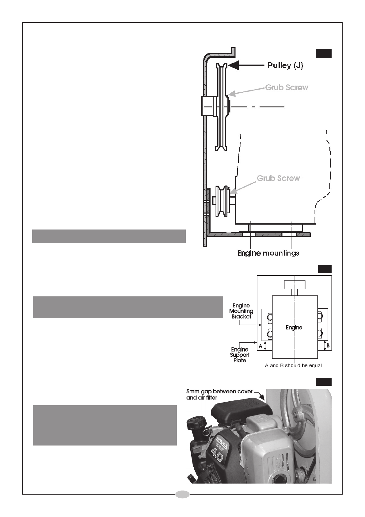
6.1 Bolt the Inner Cover (K) to the Bearing Block (X).
Use two M8 x 25mm bolts, with flat washers at
the bolt heads, (within the Inner Cover), and
spring washers with nuts to the rear of the Bearing
Block. Leave the nuts loose at this stage.
6.2 Bolt on the Engine Support Plate (M), as
shown in Fig.. 7, by inserting four M6 x 65mm
bolts, with flat washers, through the holes in
a. the Support Plate (M),
b. the slotted holes in the Inner Cover (K),
c. the spacer, (which is inserted between the
Inner Cover, and the Frame
d. the Securing plate.
NOTE:
The securing plate is painted, whereas the spacer is unpainted and is the thicker of the two plates
Fig.7
o
8
Page 9
6.3 Thread on a spring washer and nut, but DO NOT tighten the nuts at this stage
6.4 When all four bolts are fitted, centralise the
Inner Cover (K) about its mountings, then fully
tighten the two bolts securing it to the Bearing
Block (X). (See Fig.7)
6.3 Slide the Pulley (J) on to the shaft, having lined
up the key and keyway, ensuring the grub
screw in the hub of the pulley faces outwards
(see Fig. 8). It may be necessary to drive the
pulley on to the shaft using a soft faced
hammer, until the end of the shaft is slightly
proud of the central boss. This is not a critical
measurement. Lock the pulley in this position
by tightening the grub screw.
6.4 Manoeuvre the Engine Support Plate (M)
upwards as far as possible, and secure in
this position temporarily, by nipping up two of
the four nuts securing it, (do not fully tighten
them) with the Support Plate judged to be as
near parallel to the ground as possible.
Fig.8
7. Mounting the Engine
7.1 Apply a little light oil to the engine output shaft,
then locate the key, firmly in the keyway.
Slide the motor pulley on to the shaft, with the grub screw,
in the centre boss, facing inwards towards to engine.
Leave the grub screw loose.
IMPORTANT! Slip the drive belt over the motor pulley, then
place the engine on to the support plate.
Enter the four M8 x 25mm bolts through the slotted holes
in the Engine Mounting and those in the Engine Support
Plate, ensuring flat washers are in place against the bolt
head. Thread on a flat washer, followed by a spring
washer and nut to each of the bolts, from below, leaving
the nuts loose.
7.2 Position the engine so that it lies entirely
square on the support plate. (One method
of achieving this is shown in Fig. 9).
It is also IMPORTANT that the engine be
positioned so that a gap of approx. 5mm
exists between the air filter housing and
the Inner Cover.
Fig.9
Fig.10
When these conditions are met, fully tighten
the engine mountings to a torque setting
of 12 ft lb.
o
9
Page 10
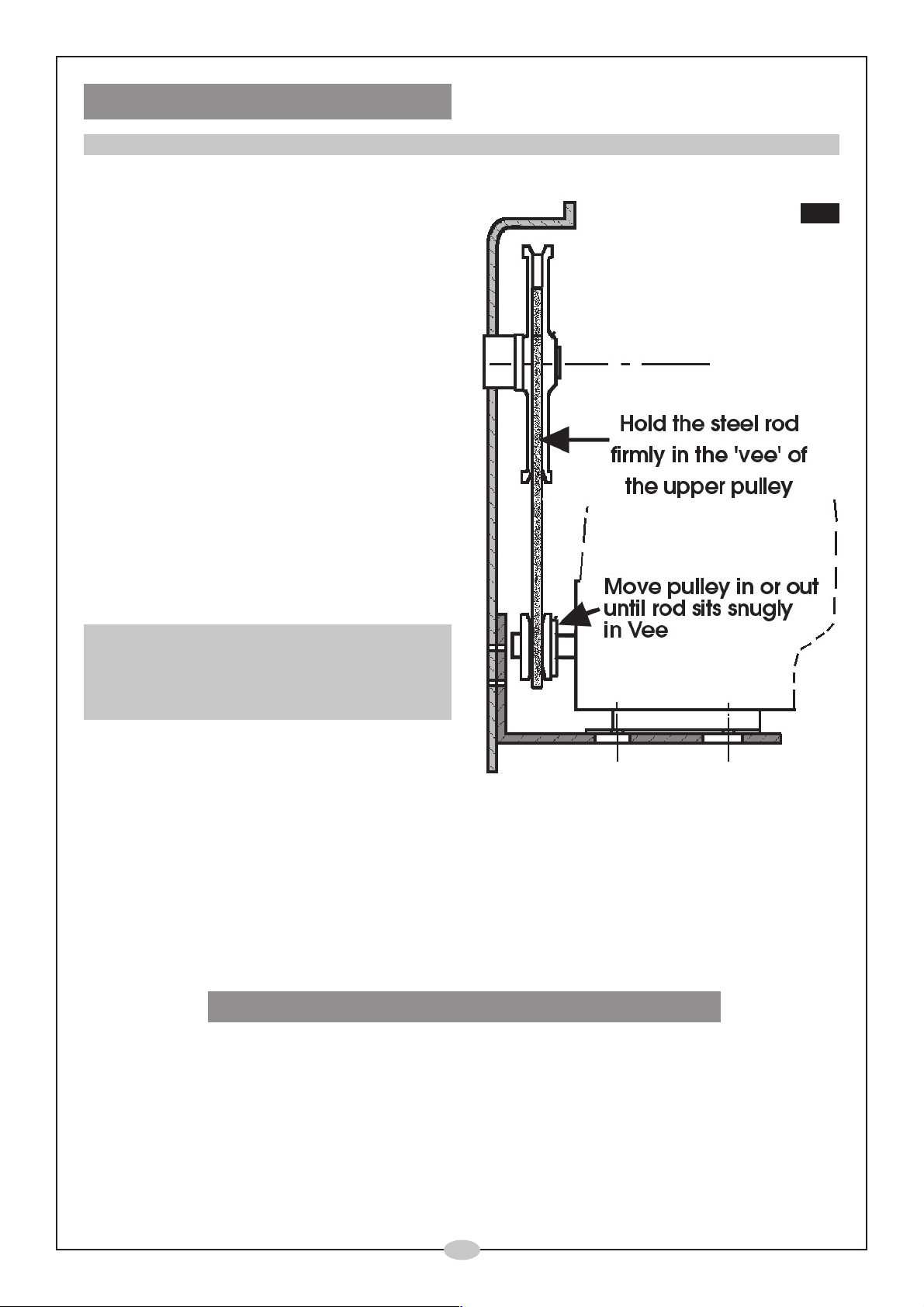
8. Fitting the Drive Belt
NOTE: It is now most important that the motor pulley be aligned so that it is directly in line with the driven pulley (J).
8.1 A piece of 6mm rod is provided which is
used to align the pulleys as follows:
Hold the rod firmly in the ‘Vee’ of the upper,
driven pulley, then rotate the pulley and
rod together so that the other end of the
rod comes into contact with the vee of
the motor pulley.
The rod should come to rest perfectly
symmetrically in the motor pulley vee’.
Move the motor pulley in or out, as
appropriate, until this condition is met.
When satisfied, tighten the motor pulley
grub screw.
It is important that time is taken to ensure
this adjustment is correct, otherwise
premature failure of the drive belt could
occur.
Fig.11
8.2 Slip the drive belt over the top pulley, then
over the motor pulley.
NOTE:
The gap between the cover and top pulley is small
but the operation is possible by rotating the upper
pulley whilst easing the belt between the cover and
pulley rim.
8.3 Slacken off the two nuts, previously nipped
up to secure the Engine Mounting Plate in
position, then push down on the engine
so that tension is applied to the belt.
Tension is correct when there is approximately ½" total movement at the centre of the belt
run when using moderate thumb pressure.
The Support Plate should be as near parallel to the ground as possible when making this
adjustment.
8.4 When satisfied, secure the Engine Support Plate by tightening the nuts behind the Securing
Plate, ensuring the Support Plate remains perfectly parallel to the ground.
CAUTION: The nuts MUST tightened progressively.
8.4 Finally, lower the Outer Cover so that the channel formed on the rim of the cover engages
over the rim of the Inner Cover. Slide the cover down as far as possible and secure with the
screws provided.
o
10
Page 11
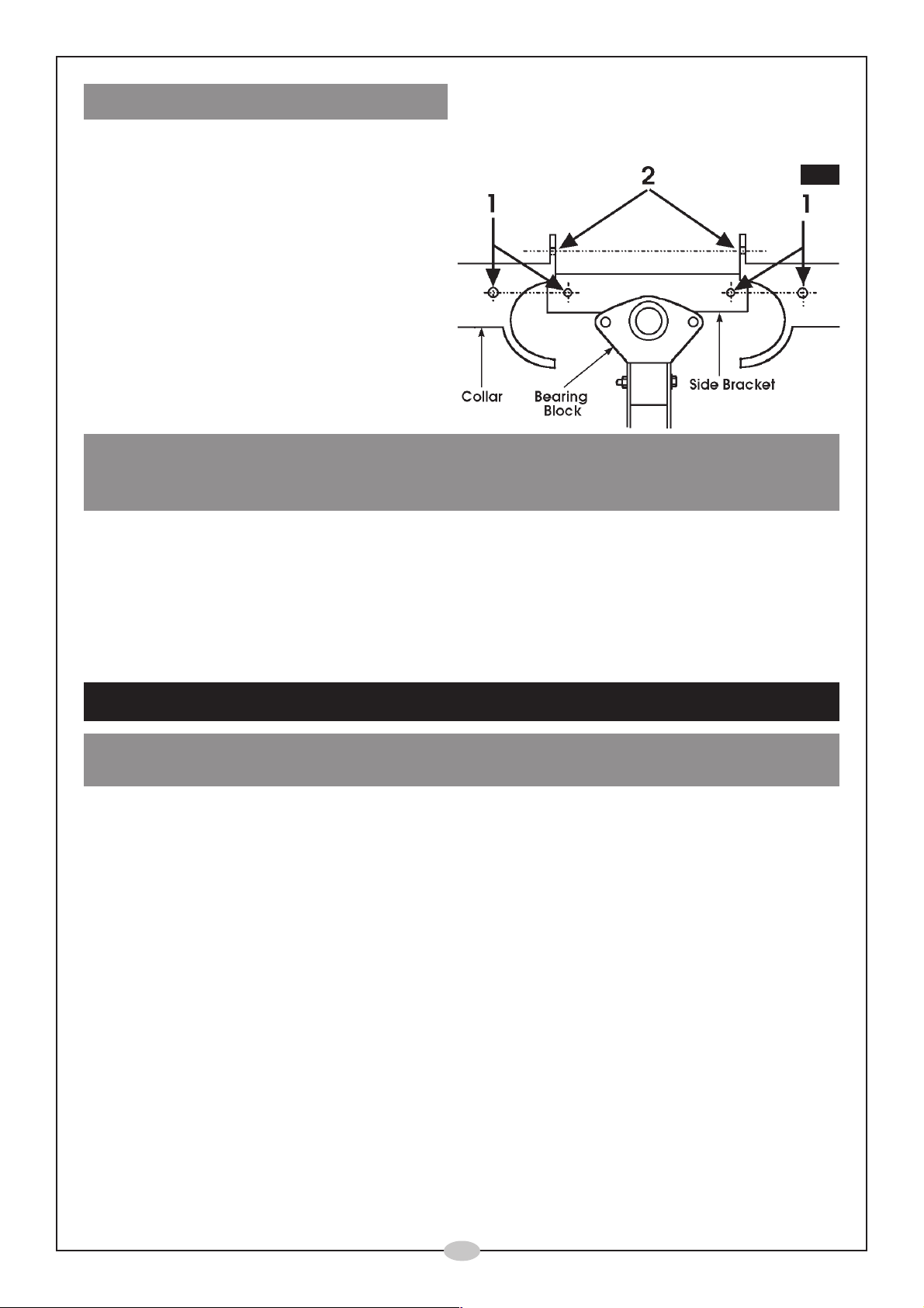
9. Fitting the Drum Collar
Before the collar is attached, it is strongly recommended that a layer of grease (not supplied)
be applied to the underside of the serrated rim of the lower drum.
9.1 Secure each half of the collar to the
side brackets first. (Shown at ‘1’, Fig.
12). Use a single M6 x 10mm bolt with
a flat and spring washer.
9.2 Bolt the two halves together using two
M6 x 20mm bolts with a flat washer,
spring washer and nut, shown at ‘2’
Fig.. 12
IMPORTANT:
The Drum Collar is a Safety Feature, and must ALWAYS be in place. NEVER operate the
machine with the collar removed.
Congratulations......your Concrete Mixer is now fully assembled and ready for use.
Fig.12
Please consult the engine manufacturers handbook, enclosed, for full details as to how to
start, operate and maintain your engine.
OPERATION
IMPORTANT:
ALWAYS start the engine and have the drum rotating, BEFORE loading the drum.
To start the engine please refer to the manufacturers handbook which accompanies this
manual.
In addition to the precautions laid out in the engine manual, ensure the throttle is set to fully
open, i.e. against the stop, before pulling the recoil starter. In this position, the engine is set to
run at an ideal speed for drum rotation.
NOTE: If the choke is used to start the engine, it is advised that you allow the engine to warm
up sufficient for the choke to be disengaged, before loading the drum.
Once the engine is running smoothly, and the drum rotating, proceed to load the drum with
sand/cement, ensuring the drum is inclined upwards (approx. 30 degrees minimum), to avoid
having the mix thrown out.
In order to rotate the drum, push the Hand Wheel inwards at the rim to disengage the wheel
from the Locking Plate. Turn the drum to the required position then release the handwheel to
lock it in that position.
o
11
Page 12
MAINTENANCE - General
Before each use
Inspect the machine to ensure it is not damaged and will perform its normal functions correctly.
If any damage is apparent, have it fixed before putting into service.
Periodically
Inject a few drops of light oil into the oil points, located on top of the Bearing Blocks and
rotate the drum to ensure distribution of oil within the bearing surface.
Inspect the paintwork and remove any rust that may be apparent before touching up where
necessary, with a rust resistant paint.
It is recommended that the Collar be removed, at least annually, and grease smeared on the
serrated underside of the lower rim. Ensure the collar is replaced correctly.
After each use.
It is strongly recommended that the machine is hosed down thoroughly with clean water, taking care
to prevent water from entering the engines electrical components by wrapping a polythene sheet or
bag over the engine during the cleaning process.
Turn the drum so that it is face down to allow all water to drain off. Protect it from the elements
by covering with a tarpaulin. This is particularly important if the machine is to be stored for a
period of time.
Storage
It is possible to fold the leg and axle assembly beneath the frame by removing their upper
mounting bolts, and slackening off the lower mounting bolts so that the leg, or axle assy.
pivots beneath the frame.
MAINTENANCE - Engine
It is important to maintain the engine
according to the manufacturers
handbook, which accompanies this
manual.
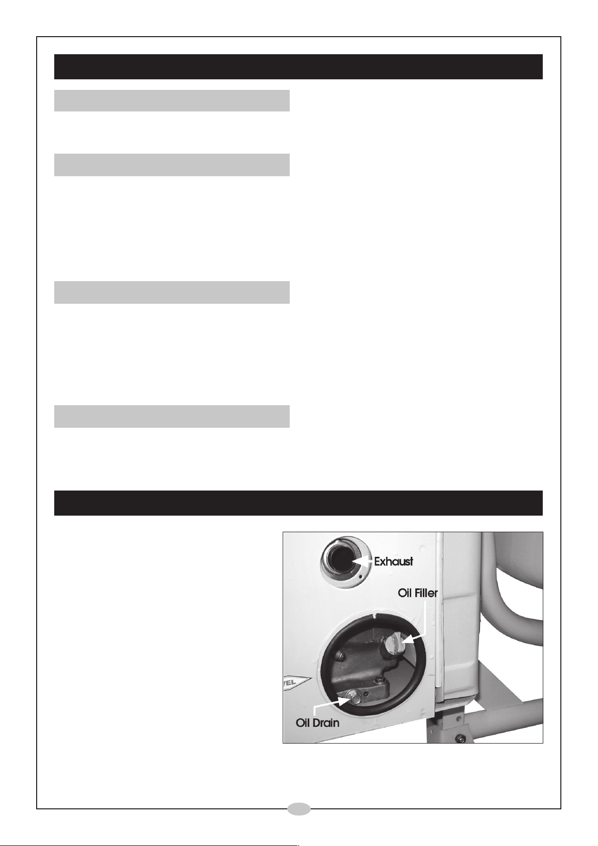
The location of the Oil Filler, and Oil
Drain, is indicated in Fig.13.
Checking oil level, topping up and
changing the oil can all be done with
the engine cover in place, as can the
air filter replacement and spark plug
maintenance. For all other work it will
be necessary to remove the cover.
o
12
Page 13

SPECIFICATIONS
Engine ............................................................................ Honda GC135
Engine Power Rating .................................................... 135cc
Drum Capacity ............................................................. 3.5 cuft / 125 litre
Dimensions .................................................................... 1190x710x465mm
Sound Power Level (Guaranteed) ............................. 94dBL
Weight............................................................................ 63kg
Part Number .................................................................. 3400820
SPARE PARTS & SERVICE CONTACTS
Please contact your nearest dealer, or
CLARKE International, on one of the following numbers.
PARTS & SERVICE TEL: 020 8988 7400
PARTS & SERVICE FAX: 020 8558 3622
WA
or e-mail as follows:
PARTS: [email protected]
SERVICE: [email protected]
o
13
Page 14
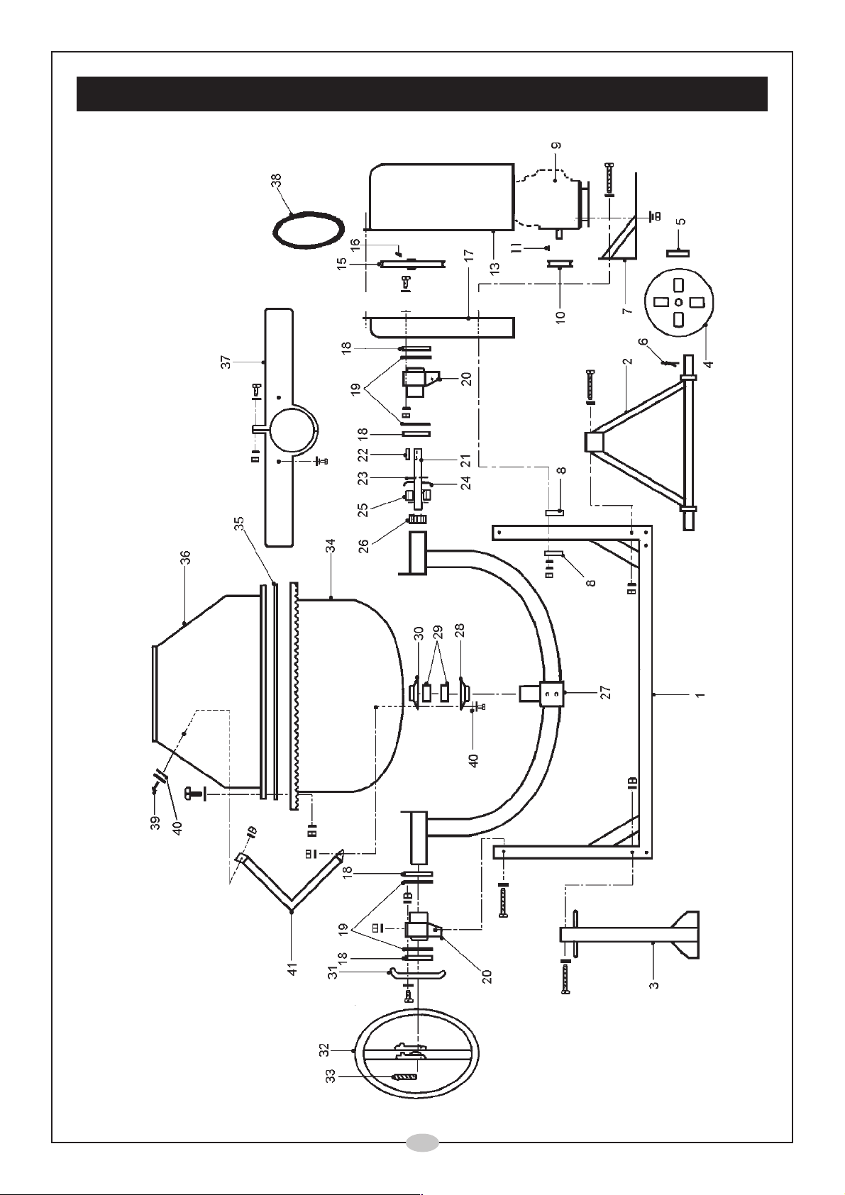
PARTS DIAGRAM
14
o
14
Page 15
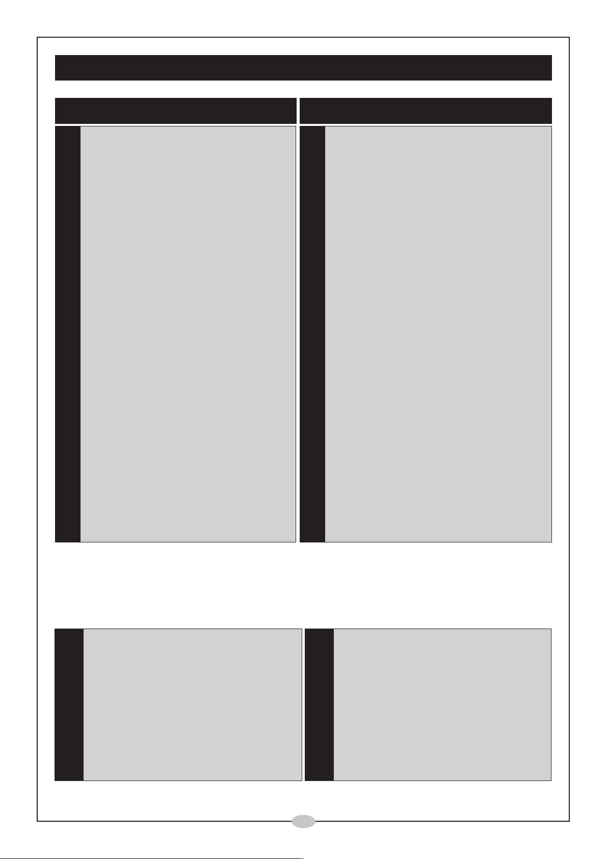
SPARE PARTS LIST
No. Description Qty Part No.
1
Frame Assy 1 SD0001
2 Axle Assy 1 SD0002
3 Leg 1 SD0003
4 Wheel 4 SD0004
5 Flat Washer 2 SD0005
6 Split pin 2 SD0006
7 Engine Support Plate 1 SD0007
8 Spacer/Plate 6mm 2 SD0008
9 Engine Assy 1 7999010
10 Pulley, Engine 1 SD0010
11 Key 1 SD0011
13 Outer Cover 1 SD0013P
15 Pulley, Drive 1 SD0015
16 Grub Screw 1 SD0016
No. Description Qty Part No.
23 Circlip 1 SD0023
24 End Cap 1 SD0024
25 Bearing Set 1 SD0025
26 Pinion 1 SD0026
27 Yolk Assy 1 SD0027
28 Bearing Plate Lower 1 SD0028
29 Bearing Set 1 SD0029
30 Bearing Plate Upper 1 SD0030
31 Locking Plate 1 SD0031
32 Hand Wheel 1 SD0032
33 Spring 1 SD0033
34 Lower Drum Assy 1 SD0034
35 Sealing Ring 1 SD0035
36 Upper Drum 1 SD0036
17 Inner Cover 1 SD0017P
18 Circlip 4 SD0018
19 Flat Washer 4 SD0019
20 Bearing Block 2 SD0020
21 Drive Shaft 1 SD0021
22 Key 1 SD0022
The following items are the nuts bolts and washers packed separately and which may be
locally procured from any Hardware or DIY store, or from your CLARKE dealer quoting the part
numbers given.
a. M5 x 10 Slot Rd Hd 5 3044701
b. M6 x 20 Hex Bolt 6 3044501
c. M6 x 16 Cross Hd 6 3044705
d. M6 x 65 Hex Bolt 4 3044702
f. M8 x 60 Hex Bolt 6 3044703
37 Collar Assy 1 SD0037
38 Drive Belt 1 SD0038
39 Mushroom Hd Bolt 2 SD0039
40 Leather Washer 4 SD0040
41 Mixing Blade 2 SD0041
42 Chain 1 SD0042
j. M8 Nut 10 3040601
k. M10 Nut 2 3040602
l. 5mm Flat Washer 4 3040574
m. 6mm Flat Washer 24 3040575
n. 8mm Flat Washer 10 3040576
g. M10 x 65 Hex Bolt 1 3044704
h. M5 Nut 11 3040608
i. M6 Nut 16 3040600
p. 5mm Spr. Washer 11 3040595
q. 6mm Spr. Washer 20 3040581
r. 8mm Spr. Washer 10 3040582
o
15
Page 16

o
 Loading...