

Page 1
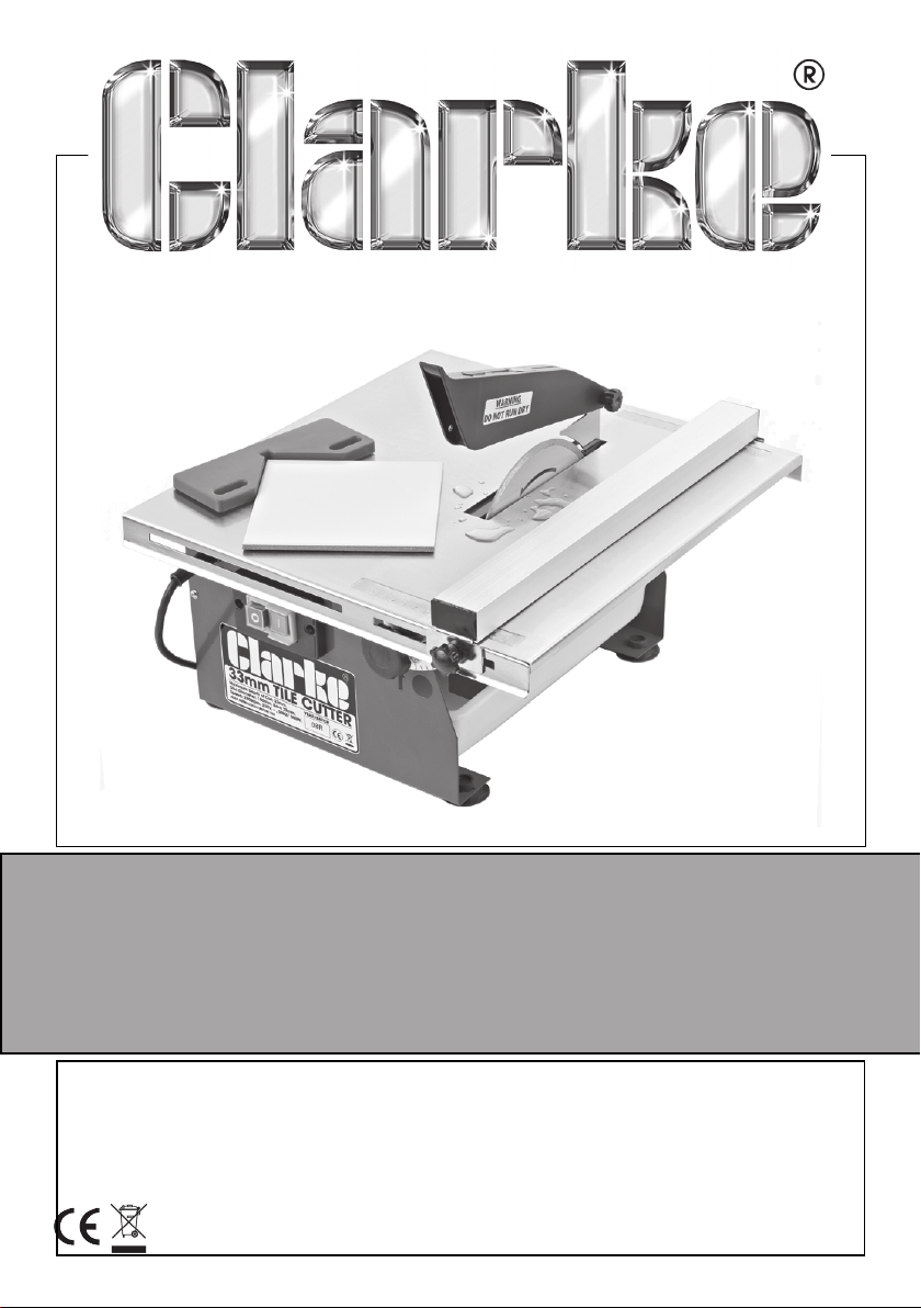
ELECTRIC TILE CUTTER
Model Nos ETC180
Part No: 3400740
ASSEMBLY & OPERATING
INSTRUCTIONS
GC05/14
Page 2

INTRODUCTION
Thank you for purchasing this CLARKE product.
Please read this manual thoroughly and follow the instructions carefully and
follow the instructions given. In doing so you will ensure the safety of yourself
and that of others around you, and you can look forward to the product
giving you long and satisfactory service.
GUARANTEE
This product is guaranteed against faulty manufacture for a period of 12
months from the date of purchase. Please keep your receipt which will be
required as proof of purchase.
This guarantee is invalid if the product is found to have been abused or
tampered with in any way, or not used for the purpose for which it was
intended.
Faulty goods should be returned to their place of purchase, no product can
be returned to us without prior permission.
This guarantee does not effect your statutory rights.
SAFETY PRECAUTIONS
WORK AREA
1. ALWAYS keep the work area clean and well lit. Floors should always be
kept clear. Cluttered or dark areas invite accidents.
2. ALWAYS keep children away and keep visitors at a safe distance from the
work area, especially whilst operating the machine.
3. ALWAYS place the machine on a firm steady base and at a comfortable
working height.
4. ALWAYS check to ensure that all other parts of the machine and the
surrounding work area are kept dry, apart from the water trough which is
provided to wet the cutting disc.
5. ALWAYS use in a well ventilated area. Never operate the cutter in the
presence of flammable vapours.
PERSONAL SAFETY
1. ALWAYS stay alert, watch what you are doing and use common sense
when operating a power tool. Do not use the machine while you are tired
or under the influence of medication, drugs or alcohol.
2
Page 3

2. NEVER over-reach. Keep your proper footing and balance at all times to
enable better control of the machine in unexpected situations.
3. ALWAYS wear safety goggles, manufactured to the latest European Safety
Standards. Everyday eyeglasses do not have impact resistant lenses and
are not safety glasses.
4. ALWAYS concentrate on the job in hand, no matter how trivial it may
seem. Accidents are caused by carelessness due to familiarity.
5. ALWAYS keep your proper footing and balance at all times. For best
footing, wear rubber soled shoes. Keep floor clear of oil, scrap wood, etc.
6. ALWAYS use a face mask to prevent inhalation of dust.
7. ALWAYS take precautions in respect of loose clothing, jewellery & long hair,
which are potential hazards which could get caught in the cutting disc.
GENERAL USE AND CARE
1. ALWAYS ensure that the cutter cannot be started inadvertently by using
the ON/OFF switch whenever carrying out maintenance.
2. ALWAYS maintain in top condition. Keep clean for the best and safest
performance. Follow maintenance instructions.
3. ALWAYS check for damage or condition that may affect the machine’s
operation. Any damage should be properly repaired or the part replaced.
If in doubt, DO NOT use the machine. Consult your Clarke dealer.
4. ALWAYS keep the mains cable well away from any machinery and ensure
an adequate electrical supply is close to hand so that the operation is not
restricted by the length of cable.
6. NEVER drag the machine by its power cable or pull the cable to
disconnect it from the power supply.
7. ALWAYS ensure the switch is off before plugging into the power supply.
8. ALWAYS examine the cutting disc before use, and replace if badly worn.
9. ALWAYS allow the motor freedom, so that the cutting disc will be cutting
at, or close to its maximum speed.
10. ALWAYS turn off the power supply before making any adjustments.
11. NEVER force the cutting disc if it is reluctant to cut properly or slows down.
12. NEVER use this machine for cutting metal or timber. This machine is for
cutting stone, ceramics, marble and similar hard material ONLY.
13. NEVER apply side thrust to the cutting disc. i.e. try to cut on one side of the
disc only.
14. NEVER operate this machine with the blade guard removed.
15. ALWAYS store out of reach of children and do not allow persons unfamiliar
with these instructions to operate this machine.
16. NEVER attempt to repair the mains cable. If the cable, or any part of the
switch assembly becomes damaged it must be replaced.
3
Page 4
ELECTRICAL CONNECTIONS
This product is provided with a 13 amp BS 1363 plug, fitted with a 13amp fuse and
MUST be connected to a standard, 230 Volt (50Hz) electrical supply, preferably
through an approved plug, or a suitably fused isolator switch.
WARNING: THIS APPLIANCE MUST BE EARTHED
IMPORTANT: The wires in the mains lead should be connected in accordance
with the following colour code:
Green & Yellow - Earth
Blue - Neutral
Brown - Live
As the colours of the flexible cable of this appliance may not correspond with
the coloured markings identifying terminals in your plug, proceed as follows:
•
Connect the GREEN & YELLOW coloured cord to the plug
terminal marked with a letter E or Earth symbol “
coloured GREEN or GREEN & YELLOW.
• Connect the BROWN coloured cord to the plug terminal
marked a letter “L” or coloured RED.
•
Connect the BLUE coloured cord to the plug terminal marked
a letter “N” or coloured BLACK
If this appliance is found to be fitted with a plug which is moulded on to the
electric cable (i.e. non-rewireable) please note:
1. The plug must be thrown away if it is cut from the electric cable. There is a
danger of electric shock if it is subsequently inserted into a socket outlet.
2. Never use the plug without the fuse cover fitted.
3. Should you wish to replace a detachable fuse carrier, ensure that the
correct replacement is used (as indicated by marking or colour code).
4. Replacement fuse covers can be obtained from your local Clarke dealer
or most electrical stockists.
” or
FUSE RATING
The fuse in the plug must be replaced with one of the same rating and this
replacement must be ASTA approved to BS1362.
We strongly recommend that this machine is connected to the mains supply
via a Residual Current Device (RCD).
4
Page 5
UNPACKING
When unpacking please check contents and advise your dealer immediately
if any parts are missing. The essential parts of the machine are as follows;
1. ETC180 Tile Cutter
2. Open Spanner
3. Special Spanner
4. Mitre Guide
5. Blade Guard Arm
6. Guard Bracket
7. Water Tray
8. Instruction Manual (this document)
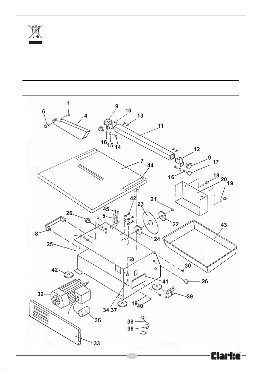
All item numbers in the following text refer to the diagram on page 9.
ASSEMBLY
Although the machine is portable, always ensure its temporary working
location is flat and even, and at a convenient height with adequate lighting.
The machine is supplied
fully assembled, other than
the blade guard, which
must be fitted as follows:
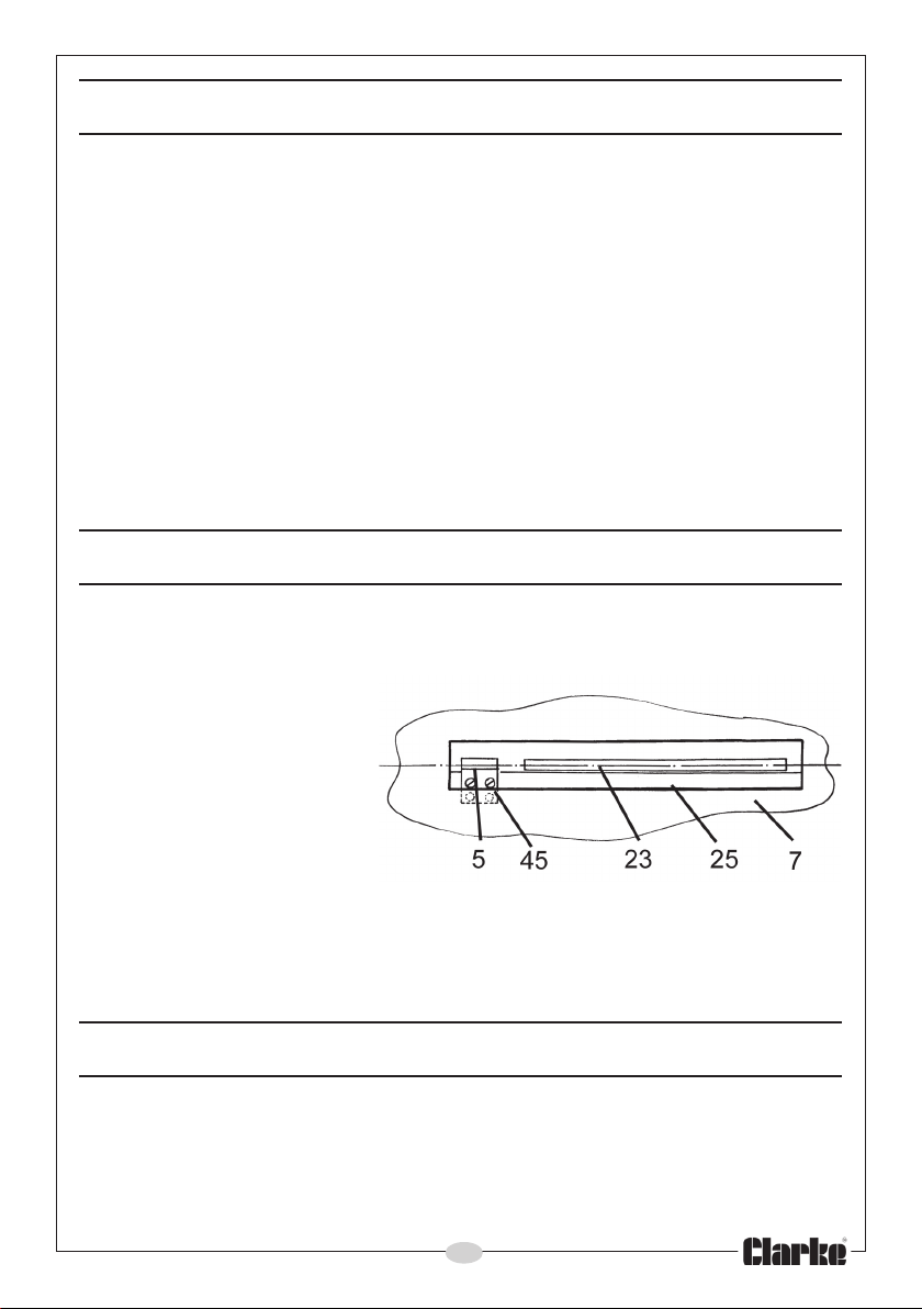
1. Insert screws (45)
through the gap in the
table top (7) and screw
the guard support
bracket into frame (25)
below.
2. Attach the blade guard (4) to the bracket (5) by screwing the guard
securing knob (6) through the holes and into the captive nut (1) in the
guard.
OPERATION
1. Measure the tile or piece of material to be cut and proceed to adjust:
A) The angle of the table, which can be adjusted up to 45 degrees
from the horizontal for mitre edge cuts if required. For normal
perpendicular cuts, the table should be set to zero degrees on the
bevel scale.
5
Page 6
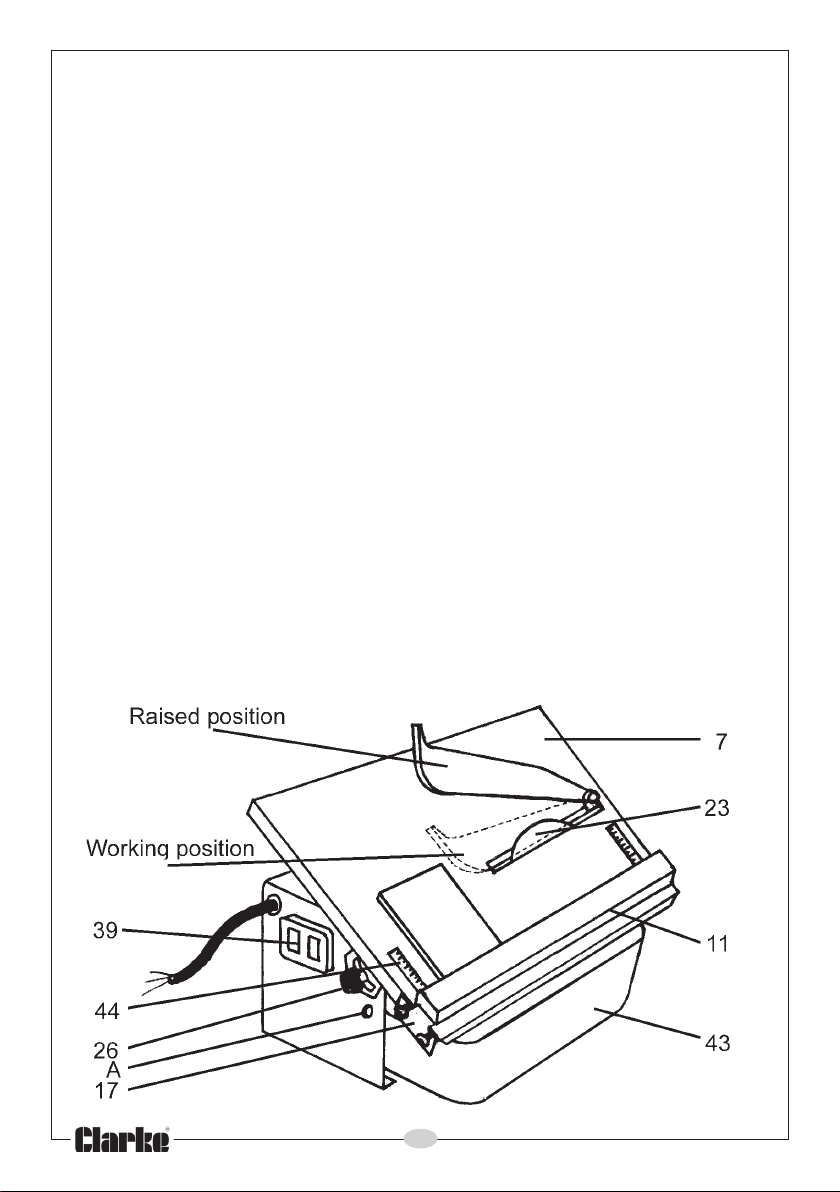
B) The position of the fence on the table top. To ensure accurate cuts,
check the alignment of the fence by reference to the calibrated
scale, set into each end of the table top.
2. Re-tighten all locking knobs securely to ensure secure positions for both
the table top and the fence.
3. Fill the water trough (43) located underneath the table with just sufficient
water so that the edge of the cutting disc can be kept constantly wet. Do
not overfill as this can cause an unnecessary mess. Check the water level
constantly during use and top up as necessary. A filling hole (A), which
can accommodate, for example, a small watering can, is be found in the
front face of the machine frame.
4. Adjust the blade guard position, ensuring that there is sufficient room for
the tile to pass between the table top and the guard. The guard should
be parallel to the surface of the table with the minimum clearance
between the guard and the tile.
5. Start the machine by pressing the green button on the ON/OFF switch
(39), marked ‘I’.
6. Hold the material firmly at all times against the parallel fence, or hold it in
the mitre gauge, as required. Move it steadily over the table, into the
cutting edge of the disc.
7. DO NOT force the cutting disc through the tile. Keep the speed of the disc
as near to its maximum speed as possible.
8. Always cut in a straight line. DO NOT attempt to cut a curved line.
9. Keep hands well clear of the disc whilst it is in motion. Remove all pieces
using a piece of wood, or similar, before making the next cut.
6
Page 7
10. To stop the machine at any time, press the red stop button marked ‘O’.
Always do this as soon as cutting has been completed, and before
making any adjustments to the machine.
NOTE:
Bevel cuts are usually made on the right side of the cutting disc,
i.e. on the ‘downward’ slope side of the disc, so that the glazed
side of the tile is uppermost, and as there is little room here for the
parallel fence, this operation is usually carried out freehand. DO
NOT exert side pressure on the cutting disc.
NOTE: In order to get the feel of the machine and reduce the possibility
of wastage, we recommend that trial cuts are made first with
surplus or scrap material of a similar type to that to be cut.
CHANGING THE CUTTING DISC
1. Ensure that the machine is switched off and disconnected from the mains.
2. First remove the water trough, then remove the two screws securing the
cutting disc cover, beneath the table, and withdraw the cover.
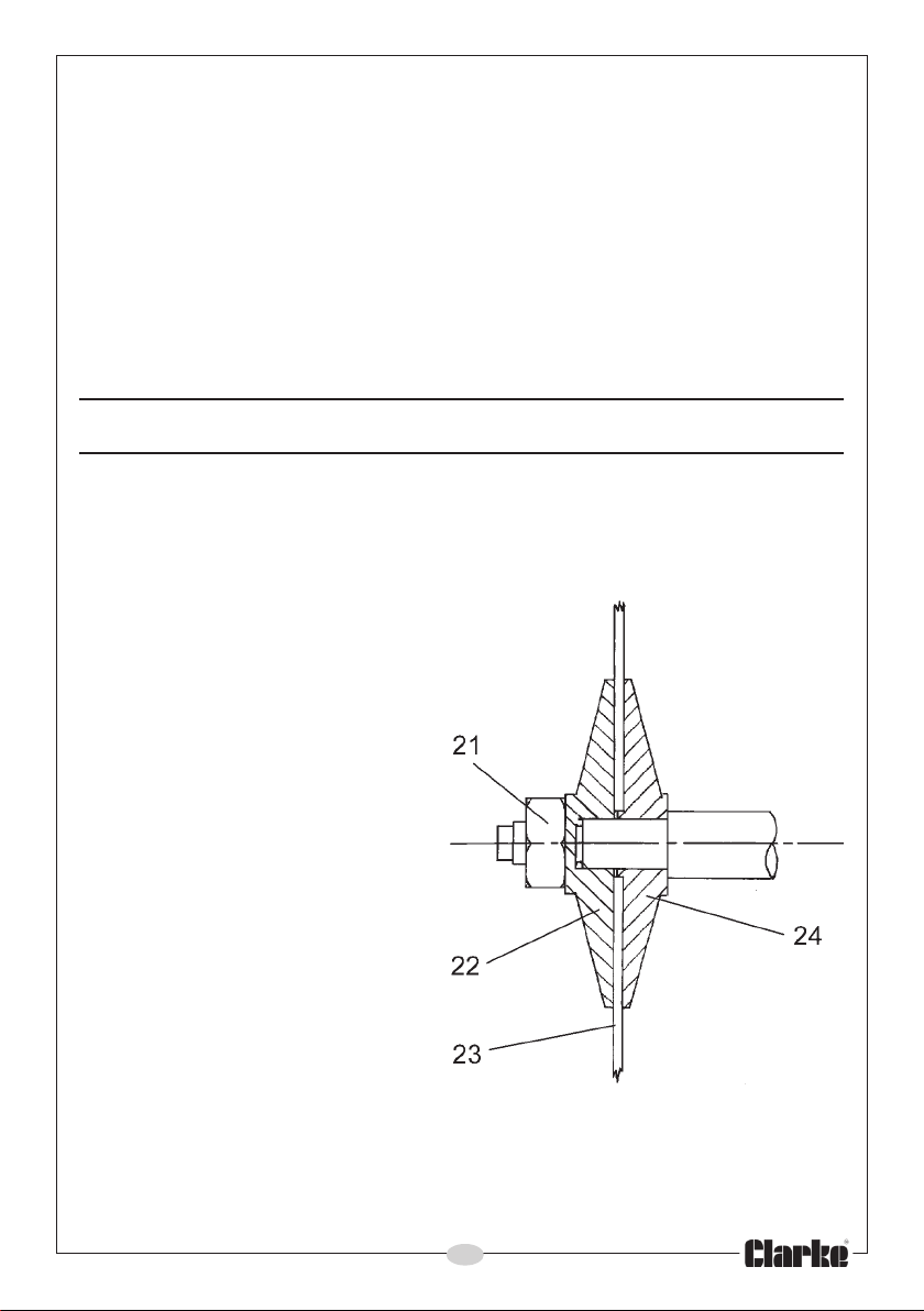
3. Undo the disc securing nut (21)
using the spanner supplied.
The drive shaft has two flats
milled on its end, allowing a
second spanner (supplied) to
be used to restrain the shaft
from rotating.
4. Pull off the clamping disc,(22)
followed by the cutting disc
(23).
5. Take this opportunity to clean
the drive-shaft of any foreign
matter.
6. Replace the cutting disc,
ensuring the direction of
rotation is correct. If in
doubt, take note that the shaft
rotates in an anticlockwise
direction as you look directly at
it. The disc must be fitted so that
the arrow on the cutting disc,
points in the SAME direction.
7. Replace the clamping plate and the nut. It is sufficient that the nut be
tightened only as much as is possible whilst holding the disc by hand. DO
NOT overtighten.
7
Page 8

MAINTENANCE
When carrying out servicing or maintenance tasks...ALWAYS disconnect the
machine from the mains supply.
Always rotate the cutting disc by hand before use, to check for cracks or
distortion. If any damage is detected, renew the disc.
Check the power cable to ensure it is in perfect condition.
Drain the water tank after use and ensure it is dry before storing.
ALWAYS maintain the machine in top condition. When not in use, keep it
covered, and store in a dry place, not exposed to the elements.
SPECIFICATION
Motor ....................................................................................... 230V, 50 Hz 1ph
Power Rating .......................................................................... 500 Watts
Speed ...................................................................................... 2800 RPM
Fuse Rating .............................................................................. 13 Amps
Weight (net) ............................................................................ 16 kg
Cutting Angle ......................................................................... 0 - 45 degrees
Cutting Depth at 90
Cutting Depth at 45
Cutting Disc Diameter ........................................................... 180 mm
Cutting Disc Bore .................................................................... 22.2 mm
Cutting Disc Part Number ..................................................... 6490640
Sound Power Level ................................................................ 104 Lw(A)
Sound Pressure Level ............................................................. <70 dB(A)
Vibration .................................................................................. <2.5m/s
Table Dimensions.................................................................... 420x400 mm
Overall Dimensions (LxWxH) .................................................. 460x420x295 mm
O
............................................................ 33 mm
O
............................................................. 24 mm
2
ENVIRONMENTAL PROTECTION
Do not dispose of this product with general household waste. This product
contains valuable raw materials and should be disposed of appropriately at a
recognised disposal facility.
8
Page 9
Through purchase of this product, the customer is taking on the obligation to deal with the WEEE in accordance with the WEEE regulations in
relation to the treatment, recycling & recovery and environmentally
sound disposal of the WEEE.
In effect, this means that this product must not be disposed of with general
household waste. It must be disposed of according to the laws governing
Waste Electrical and Electronic Equipment (WEEE) at a recognised disposal
facility.
COMPONENT PARTS
9
Page 10
COMPONENT PARTS
oN noitpircseD oN noitpircseD
1tuN42csiDgnipmalCraeR
2a/n52emarFesaB
3a/n62bonKtnemtsujdAelbaT
4drauG72a/n
5tekcarBdrauG82a/n
auG92a/n
6bonKgniruceSdr
7poTelbaT03)01x6M(tloBegniH
8eldnaH13a/n
9paCcitsalP23rotoMevirD
01)HL(tekcarBediuGecneF33revoCevirD
11ecneF43werc
21)HR(tekcarBediuGecneF53roticapaC
31)8x5M(wercS63dnalGelbaC
41)61x6M(tloBhcaoC73pmalCelbaC
518MrehsaW83gulP&elbaC
1a/n93hctiwSFFO/NO
6
71bonKgniruceSecneF04)4M(wercS
81)6x4M(wercS14etalPhctiwS
91)4M(rehsaW24teeFrebbuR
P34knaTretaW
02revoCevitcetor
12)21M(tuN44)ylnosledomylrae(elacS
22csiDgnipmalCtnorF54)8x4M(wercS
32)0460946ontrap(csiDgnittuC
S
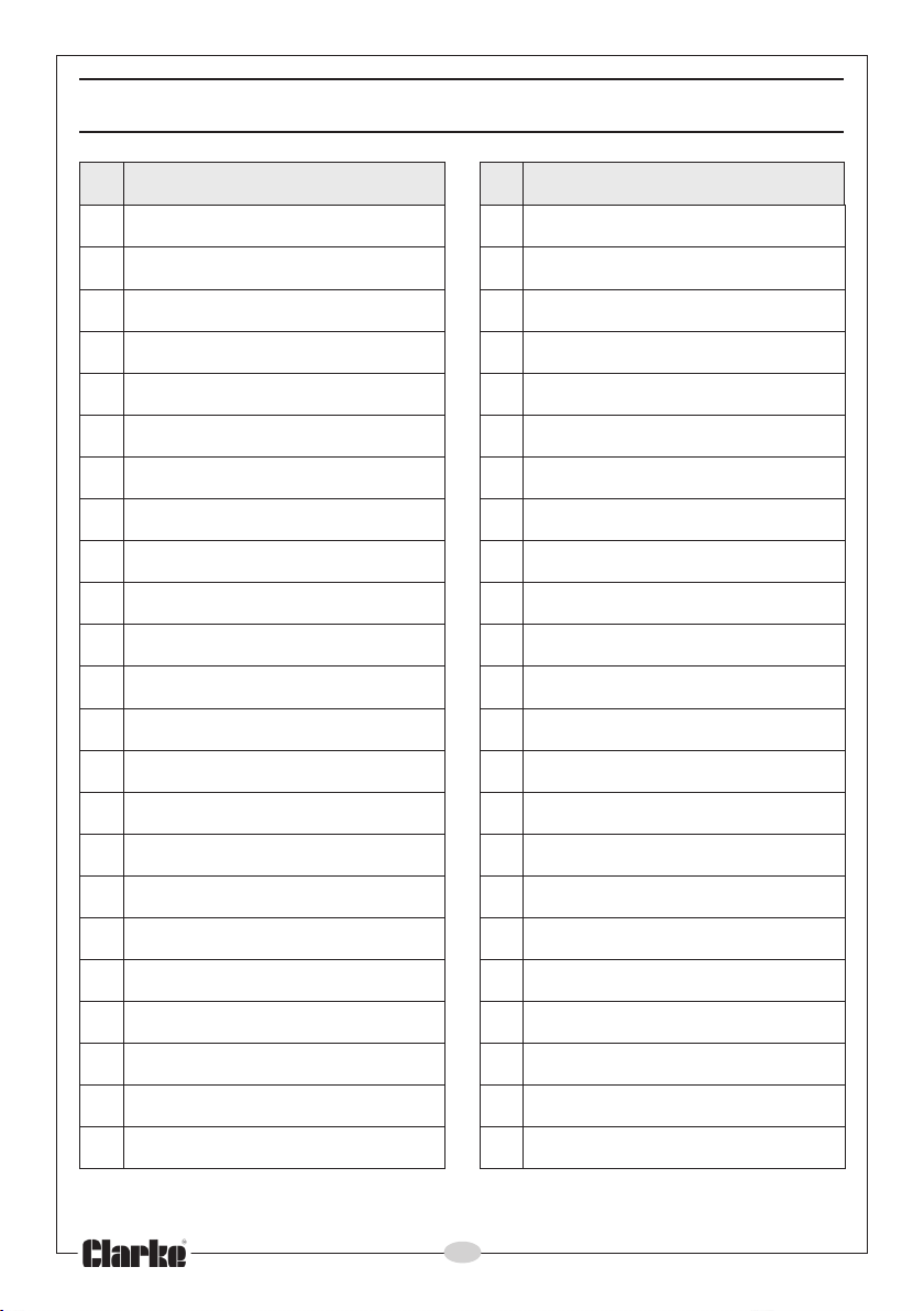
Note: All spare parts for ths product carry the prefix HT-ETC-180.
10
Page 11

DECLARATION OF CONFORMITY
11
Page 12

 Loading...