

Page 1
REVERSIBLE RATCHET
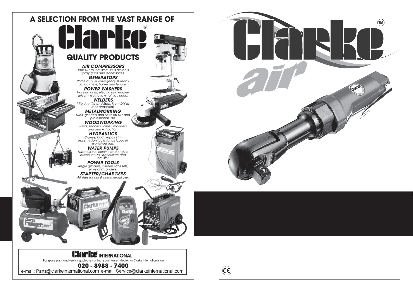
REVERSIBLE RATCHET
MODEL NOS:
CAT21 • CAT22B • CAT221B
OPERATION & MAINTENANCE
INSTRUCTIONS
0602
Page 2
Please read these instructions carefully before operating the tool
Thank you for purchasing this CLARKE Air Reversible Ratchet.
CAT 21B is a 3/8” square drive version, whereas CAT22B has a 1/2” Square drive.
CA T221B is similar to CA T 22B, but supplied with a universal joint, and a set of sockets
and screwdriver bits, complete with extension bars.
Before using the device, please read this manual thoroughly and carefully follow
all instructions given. This is for your own safety and that of others around you, and
is also to help you achieve long and trouble free service from your new tool.
GUARANTEE
This CLARKE product is guaranteed against faulty manufacture for a period of 12
months from the date of purchase. Please keep your receipt as proof of purchase.
This guarantee is invalid if the product is found to have been abused or tampered
with in any way, or not used for the purpose for which it was intended.
Faulty goods should be returned to their place of purchase, no product can be
returned to us without prior permission.
This guarantee does not effect your statutory rights.
SPECIFICATIONS
Model: CAT21B CAT22B CAT221B
Part No: 3110400 3110401 3110424
Square Drive: 3/8” 1/2” 1/2”
Max Speed: 150RPM 160RPM 160 RPM
Max Torque: 56 ft lbf 86 ft lbf 86 ft lbf
Air Inlet: 1/4” BSP 1/4” BSP 1/4” BSP
MIn Hose Size: 5/16” (8mm) ID 5/16” (8mm) ID 5/16” (8mm) ID
Air Consumption: 4 CFM 4 CFM 4 CFM
Max Air Pressure: 90 PSI (6.2 bar) 90 PSI (6.2 bar) 90 PSI (6.2 bar)
Vibration Level: See pages 7&8 See pages 7&8 See pages 7&8
Bolt Capacity 3/8” 3/8” 3/8”
Length 102 10” 10”
Weight: 1.0kg 1.2 kg 2.7kg
Please note that the details and specifications contained herein are correct at the time of going to
print. However CLARKE International reserve the right to change specifications at any time without
prior notice. Always consult the machines data plate
© Copyright CLARKE International. June 1999, All rights reserved.
- 2 -
DECLARED VIBRATION EMMISSIONS
MODEL No: CA T21B, CA T22 & CAT221B
DESCRIPTION: REVERSIBLE RA TCHET
Declared vibration emmission value in accordance with EN12096
Measured vibration emmission value Uncertainty value -
K: ...........................................................
a:..........................
9.13m/s
3.65m/s
Highest measured reading in a single plane .......................... 11.0m/s
Values determined according to EN28622-1, under the following conditions:
2
2
2
PARTS & SERVICE CONTACTS
PAR TS & SERVICE TEL: 020 8988 7400
IMPORTANT:
The use of parts other than CLARKE replacement parts may result in safety hazards,
decreased tool performance and may invalidate your warranty.
- 7 -
Page 3
HAND-ARM VIBRATION
Employers are advised to refer to the HSE publication “Guide for Employers”.
All hand held power tools vibrate to some extent, and this vibration is transmitted to the
operator via the handle, or hand used to steady the tool. Vibration from about 2 to 1500
herz is potentially damaging and is most hazardous in the range from about 5 to 20 herz.
Operators who are regularly exposed to vibration may suffer from Hand Arm Vibration
Syndrome (HAVS), which includes ‘dead hand’, ‘dead finger’, and ‘white finger’. These
are painful conditions and are widespread in industries where vibrating tools are used.
The health risk depends upon the vibration level and the length of time of exposure to
it……in effect, a daily vibration dose.
Tools are tested using specialised equipment, to approximate the vibration level generated
under normal, acceptable operating conditions for the tool in question. For example, a
grinder used at 45° on mild steel plate, or a sander on softwood in a horizontal plane etc.
These tests produce a value‘a’, expressed in metres per second per second, which
represents the average vibration level of all tests taken, in three axes where necessary,
and a second figure ‘K’, which represents the uncertainty factor, i.e. a value in excess of
‘a’, to which the tool could vibrate under normal conditions. These values appear in the
declaration on page 7.
Y ou will note that a third value is given in the specification - the highest measured reading
in a single plane. This is the maximum level of vibration measured during testing in one of
the axes, and this should also be taken into account when making a risk assessment.
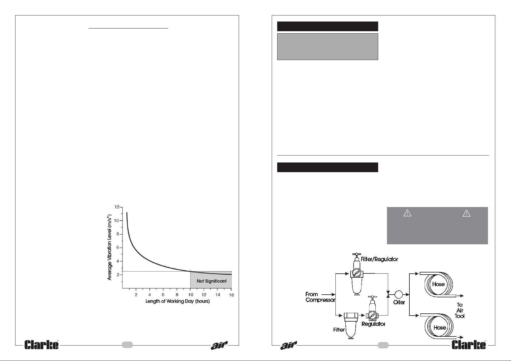
‘a’ values in excess of 2.5 m/s2 are considered hazardous when used for prolonged periods.
A tool with a vibration value of 2.8 m/s2 may be used for up to 8 hours (cumulative) per
day, whereas a tool with a value of 11.2 m/s2 may be used for ½ hour per day only.
The graph below shows the vibration value against the maximum time the respective
tool may be used, per day.
The uncertainty factor should
also be taken into account
when assessing a risk. The two
figures ‘a’ and ‘K’may be
added together and the
resulant value used to assess the
risk.
It should be noted that if a tool
is used under abnormal, or
unusual conditions, then the
vibration level could possibly
increase significantly. Users must
always take this into account
and make their own risk
assessment, using the graph as
a reference.
Some tools with a high vibration value, such as impact wrenches, are generally used for
a few seconds at a time, therefore the cumulative time may only be in the order of a few
minutes per day. Nevertheless, the cumulative effect, particularly when added to that
of other hand held power tools that may be used, must always be taken into account
when the total daily dose rate is determined.
SAFETY PRECAUTIONS
IMPORTANT
Failure to follow these precautions
could result in personal injury, and/or
damage to property.
❐ When operating this tool, ALW AYS wear:
approved impact resistant SAFETY
GOGGLES. (Eye glasses are NOT afety
glasses)
❐ ALWAYS disconnect the tool when not
in use, and before carrying out any
maintenance
❐ ALWAYS maintain the tool with care. Keep
it clean for best and safest performance.
❐ NEVER wear ill fitting clothing, remove
watches and rings.
❐ Quick change couplings should not be
located at the tool. They add weight
and could fail due to vibration.
AIR SUPPLY
Tools of this type, operate on a wide range
of air pressures. It is recommended that air
pressure to this tool does not exceed 90 PSI
(6.1bar), at the tool when running. Higher
pressure and unclean air, will shorten the
tools’ life because of faster wear , and could
be a safety hazard.
Water in the air line will cause damage to
the tool, ensure it is properly maintained at
all times.
The recommended procedure to connect
this tool to an air supply, is shown below
❐ DO NOT over-reach. Keep your proper
footing and balance at all times.
❐ DO NOT force or misuse the tool. It will
do a better and safer job at the rate for
which it was designed.
❐ DO NOT abuse hoses or connectors.
NEVER carry a tool by the hose, or yank
it to disconnect from the air supply. Keep
hoses away from heat, oil and sharp edges.
Check hoses for leaks or worn condition
before use, and ensure that all connec
tions are secure.
❐ DO NOT exceed 90 PSI at the tool.
❐ DO NOT modify the tool in any way.
❐ DO NOT remove any labels. Damaged
labels should be replaced.
❐ This tool vibrates with use. Vibration may
be harmful to your hands or arms. Stop
using the tool if discomfort, a tingling
feeling or pain occurs. Seek medical
advice before resuming use.
The air inlet used for connecting air supply,
has a standard ¼” BSP thread.
Line pressure, or hose inside diameter , should
be increased to compensate for unusually
long air hoses (over 10m). Minimum hose
diameter should be 6mm (¼") ID., and fittings
should have the same inside dimensions.
WARNING
Compressed air can be dangerous. Ensure
that you are thoroughly familiar with all
precautions relating to the use of
compressors and compressed air supply.
- 6 -
- 3 -
Page 4
ASSEMBLY
Connect a suitable hose to the Ratchet
using a ¼” hose adapter , (A recoil hose with
Quick Fit coupling is available from your
CLARKE dealer), then connect the other
end to the airline.
NOTE: ensure the airline is turned off.
Your Ratchet is now ready for use.
WARNING
NEVER use standard hand sockets, as
these could shatter with serious
consequences, use only impact sockets,
which must be in good condition.
MAINTENANCE
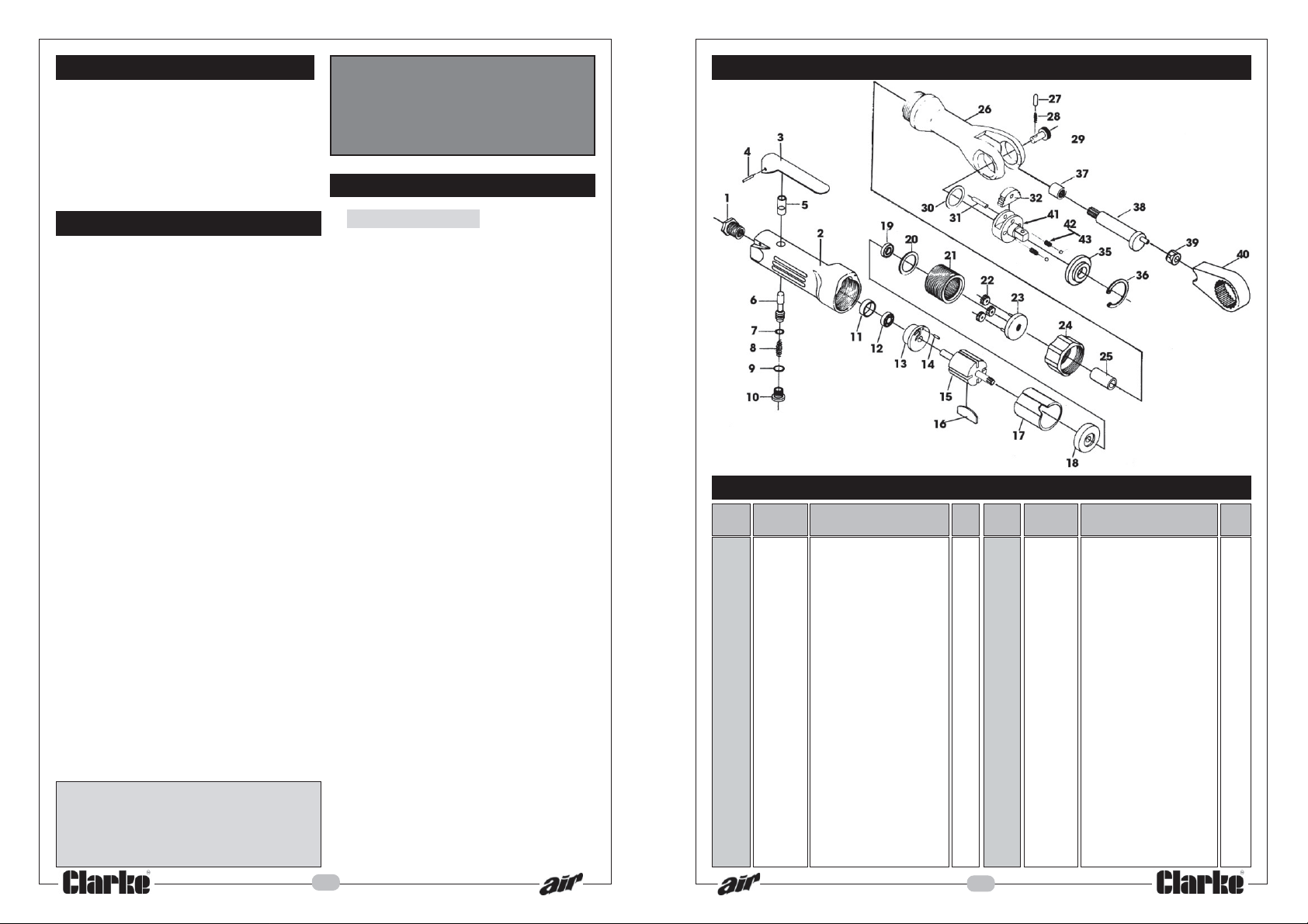
PAR TS DIAGRAM
OPERATING INSTRUCTIONS
Before starting work drain any water from the
air tank and blow condensation from the air
line. Drain compressor more frequently in hot
humid weather.
Turn ON the air supply, and check for air leaks.
If any are apparent, rectify before
proceeding. Ensure the operating pressure is
set to 6.2bar
The speed ratchet was designed, and is
ideally suited for quick removal and
installation of nuts, bolts, spark plugs and
other fasteners where space is limited.
For removal , set direction of rotation, forward
or reverse, choose correct socket etc to fit
fastener, place Speed Ratchet on fastener
and break loose by hand. Depress throttle
lever , the air power tool will complete the job.
Use penetrating oil for rusted fasteners if
necessary.
When assembling,start fasteners by hand,
again set rotation forward or reverse, apply
Speed Ratchet gently depress throttle lever,
and run down with power.
Since torque is deliberately limited, it is virtually
impossible to overtighten or damage smaller
threads. Final tightening is completed by hand.
NOTE:
When critical torque values are not required,
turn the nut or bolt one quarter to one half a
turn until it fits snugly - slightly more if gaskets
are used between surfaces.
For additional power on disassembly workturn
regulator out to it’s highest setting, (maximum
pressure).
IMPORTANT
Where torque settings are critical, the final
tightening of nuts or bolts must be by
hand,using a calibrated torque wrench.
Daily before use.
1. Drain water from air tank, air line and
compressor.
2. Check and clean, if necessary, the air
inlet gauze filter .
3. Pour a few drops of CLARKE Air Line Oil
(approx 3cc), into the air inlet. This should
be carried out regardless of whether or
not an air line lubricator is used.
If an Air line lubricator is NOT used, this
procedure should be repeated after
every two to three hours of use.
If the Ratchet is to be stored, or is idle for
longer than 24 hours, run a few drops of
Clarke Air Line Oil into the air inlet, and run
the tool for 5 seconds in order to lubricate
the internal parts.
For lubricating the air motor when in
operation, an air line lubricator should be
used, with Clarke Air Line Oil, adjusted to 2
drops per minute.
Clarke Air Line Oil is available from your
CLARKE dealer, part no. 3050825.
Be aware that factors other than the tool may
effect its operation and efficiency, such as
reduced compressor output, excessive drain
on the airline, moisture or restrictions in the
line, or the use of connectors of improper size
or poor condition which will reduce air supply.
Grit or gum deposits in the tool may also
reduce efficiency. This condition can be
corrected by cleaning the air strainer and
flushing out the tool with gum solvent oil, or
failing this, the tool should be disassembled,
thoroughly cleaned, dried and reassembled.
If the tool runs erratically or becomes
inefficient, and the air supply is sound,
dismantle the air motor and replace worn or
damaged parts, or take the tool to your
CLARKE dealer.
- 5 -
PAR TS LIST
Item Part Item Part
No. No. No. No.
1 106301 Bushing - Air Inlet 1 22 106322 Gear 3
2 106302 Handle 1 23 106323 Gear Plate 1
3 106303 Throttle Lever 1 24 106324 Clamp - Housing 1
4 106304 Pin 1 25 106325 Bearing 1
5 106305 Throttle Bushing 1 26 103326 Ratchet Housing 1
6 106306 Valve - Throttle 1 27 106327 Pin - Lock 1
7 106307 ‘O’ Ring 1 28 106328 Spring - Ratchet 1
8 106308 Spring - Throttle 1 29 106329 Button - Reverse 1
9 106309 ‘O’ Ring 1 30 106330 Washer 1
10 106310 Plug - Throttle Valve 1 31 106331 Pin 1
11 106311 Bearing Cap 1 32 106332 Pawl - Ratchet 1
12 106312 Bearing 1 35 106335 washer 1
13 106313 Plate - Front End 1 36 106336 Retaining Ring 1
14 106314 Pin 1 37 106337 Bearing 1
15 106315 Rotor 1 38 106338 Shaft - Crank 1
16 103316 Rotor Blade 4 39 103339 Bushing - Drive 1
17 106317 Cylinder 1 40 106340 Yoke - Ratchet 1
18 106318 Plate - Rear End 1 41 106341 3/8” Sq. Drive (CAT22) 1
19 106319 Bearing 1 41 106341A 1/2” Sq. Drive 1
20 106320 Bearing Cap 1 42 106342 Spring 2
21 106321 Spindle Housing 1 43 106343 Steel ball 2
Description Description
Qty Qty
- 6 -
 Loading...