

Page 1
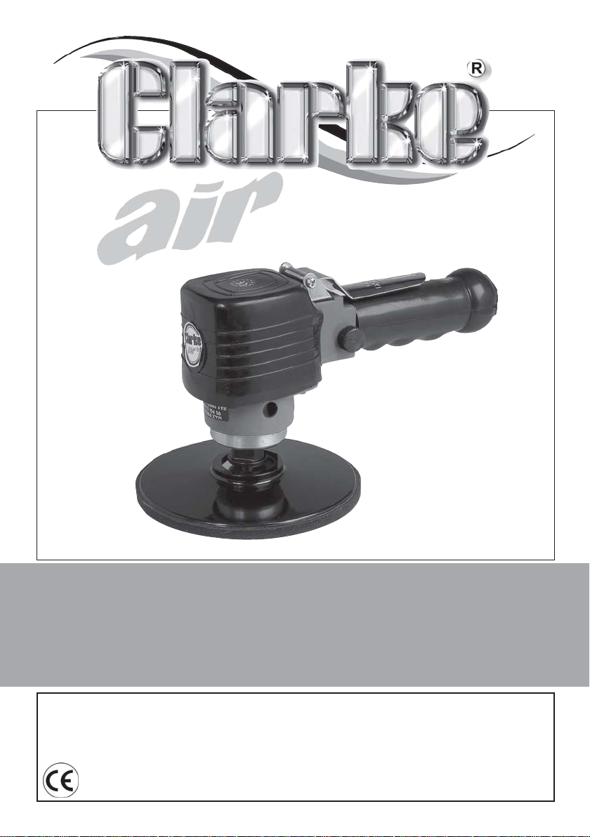
HD DUAL-ACTION SANDER
Model Nos: CAT24B & CAT93
Part No: 3110403 & 3110849
OPERATION & MAINTENANCE
INSTRUCTIONS
GC11/12
Page 2
INTRODUCTION
Thank you for purchasing this CLARKE air tool.
Before attempting to use the product, it is essential that you read this manual
thoroughly and carefully follow all instructions given. In doing so you will
ensure the safety of yourself and that of others around you, and you can also
look forward to the product giving you long and satisfactory service.
GUARANTEE
This CLARKE product is guaranteed against faulty manufacture for a period of
12 months from the date of purchase. Please keep your receipt as proof of
purchase.
This guarantee is invalid if the product is found to have been abused or
tampered with in any way, or not used for its intended purpose.
Faulty goods should be returned to their place of purchase, no product can
be returned to us without prior permission. This guarantee does not effect
your statutory rights.
ENVIRONMENTAL PROTECTION
Do not dispose of this product with general household waste. All tools,
accessories and packaging should be sorted, taken to a re-cycling
centre and disposed of appropriately.
2
Parts & Service: 020 8988 7400/E-mail:[email protected] or [email protected]
Page 3

TABLE OF CONTENTS
INTRODUCTION ......................................................................... 2
GUARANTEE ............................................................................... 2
ENVIRONMENTAL PROTECTION ................................................ 2
TABLE OF CONTENTS .................................................................. 3
SAFETY PRECAUTIONS ................................................................ 4
OVERVIEW .................................................................................. 6
AIR SUPPLY REQUIREMENTS........................... ............................ 7
ASSEMBLY ................................................................................... 8
OPERATION.............................................................................. ....9
TROUBLESHOOTING....................................................................10
MAINTENANCE .......................................................................... 11
PARTS LIST & DIAGRAM...............................................................12
SPECIFICATIONS .................................................................... ... 14
DECLARATION OF CONFORMITY ....................................... ..... 15
3
Parts & Service: 020 8988 7400/E-mail: [email protected] or [email protected]
Page 4
SAFETY PRECAUTIONS
CAUTION: FAILURE TO FOLLOW THESE PRECAUTIONS COULD RESULT IN
PERSONAL INJURY, AND /OR DAMAGE TO PROPERTY
WORK ENVIRONMENT
• Keep the work area clean and tidy.
• Dress appropriately - Do not wear loose clothing or jewellery. Tie long hair
out of the way.
• Keep children and visitors away - Do not let children handle the tool.
Make sure that any other persons in the work area are dressed suitably
and are wearing eye and ear protectors.
• Keep the air supply hose away from heat, oil and sharp edges.
• Do not fit the tool to any stand or clamping device that may damage the
tool.
GENERAL USE
• Stay alert and use common sense - do not use the tool when you are tired
or under the influence of alcohol, drugs or medication.
• Always wear eye protection when using the tool - eye protection must
provide protection from the front and the side.
• Always wear ear protectors when using the tool.
• Do not over-reach - keep proper footing and balance at all times.
• Never use any type of bottled gas as a source of power for the tool.
• Do not connect the air supply hose with your finger on the trigger of the
tool.
• Do not exceed the maximum pressure for the tool: 90 psi / 6.2 bar.
• Check hoses for leaks or worn condition before use and ensure that all
connections are secure.
• Do not use the tool for any other purpose than that described in this
booklet.
• Do not carry out any alterations or modifications to the tool.
• Always disconnect from the air supply when:
a) Performing any maintenance.
b) The tool is not in use.
4
Parts & Service: 020 8988 7400/E-mail:[email protected] or [email protected]
Page 5

c) The tool will be left unattended.
d) Moving to another work area.
• Never use the tool if it is defective or operating abnormally.
• The tool should be serviced as required by your CLARKE dealer.
• Avoid damaging the tool for example by applying excessive force.
• ALWAYS maintain the tool with care. Keep it clean for best and safest
performance.
• ALWAYS ensure the workpiece is firmly secured leaving both hands free to
control the tool.
• ALWAYS ensure the tool has stopped before putting it down after use.
• ALWAYS ensure that any attachments are correctly fastened before
connecting the tool to the power supply.
• Quick change air-line couplings should not be located at the tool. They
add weight and could fail due to vibration.
• DO NOT force or misuse the tool. It will do a better and safer job operating
at the rate for which it was designed.
• Do not remove any labels. Damaged labels should be replaced.
• This tool vibrates during use. Vibration may be harmful to your hands or
arms. Stop using the tool if discomfort, a tingling feeling or pain occurs and
seek medical advice before resuming use.
TRANSPORTATION
• Never carry the tool by the air supply hose.
• Never carry the tool with your finger on the trigger.
STORAGE
• When not in use the tool must be disconnected from the air supply and
stored in a dry place out of the reach of children (preferably in a locked
cabinet).
o
• Avoid storage in environments where the temperature is below 0
5
Parts & Service: 020 8988 7400/E-mail: [email protected] or [email protected]
C.
Page 6
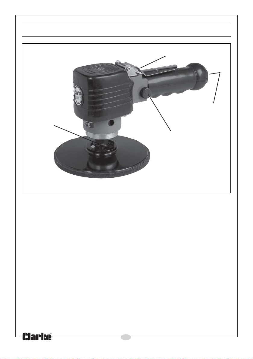
OVERVIEW
THROTTLE
AIR INLET
LOCKING NUT
REGULATOR VALVE
The CAT24B and CAT 93 Sanders are ideal for use in garages and workshops.
Random orbit sanders give a virtually scratch - free finish on various surfaces
prior to painting or varnishing the finished surface.
The only difference between the two sanders is that the external parts on the
CAT93 are highly polished and include rubber grips. Should you require any
component parts, refer to pages 12 and 13 in the manual and contact your
Clarke dealer.
When unpacking the tool, any damage or deficiency should be reported to
your CLARKE dealer immediately. The carton contains:
• Heavy Duty Dual Action Sander
• 6” Sanding Pad
• Operators Manual (this document)
Your dual -acting sander has been designed to give long and trouble free
service. If, however, having followed the instructions in this booklet carefully,
you encounter problems, take the unit to your local CLARKE dealer.
6
Parts & Service: 020 8988 7400/E-mail:[email protected] or [email protected]
Page 7
AIR SUPPLY REQUIREMENTS
WARNING: COMPRESSED AIR CAN BE DANGEROUS. ENSURE THAT YOU
ARE THOROUGHLY FAMILIAR WITH ALL PRECAUTIONS RELATING TO THE
USE OF COMPRESSORS AND COMPRESSED AIR SUPPLY.
• Use only clean, dry, regulated compressed air as a power source.
• Air compressors used with the tool must comply with the appropriate
European Community safety directives.
• A build up of moisture in the air compressor will accelerate wear and
corrosion in the moving parts. Ensure any moisture is drained from the
compressor daily and the inlet filter is kept clean.
• If an unusually long air hose is required, (over 8 metres), line pressure may
need to be increased.
• Never exceed the maximum operating pressure for the tool.
• The air hose must be rated at least 150% of the maximum operating
pressure of the tool.
• A pressure of 90psi with a flow of 6 cfm is required. Too high an air pressure
will shorten the life of the tool due to excessive wear.
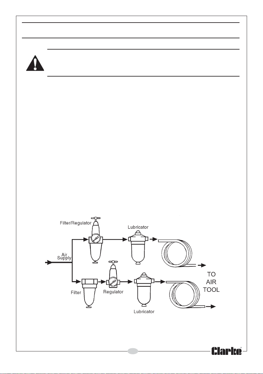
A typical airline layout is shown. If an automatic in-line filter/regulator/
lubricator unit is used it will keep the tool in good condition, but should be
regularly checked and topped up with oil.
7
Parts & Service: 020 8988 7400/E-mail: [email protected] or [email protected]
Page 8
ASSEMBLY
INSTALLING THE DISC
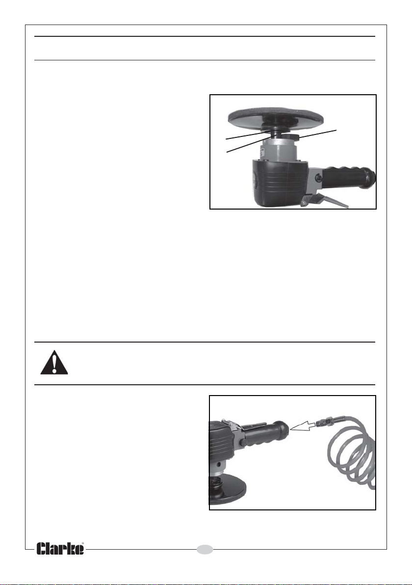
1. To assemble the pad to the tool,
turn the locking nut (A) until the
knurled portion contacts the flat
surface on the output spindle (B).
2. Thread the pad into the spindle
by gripping the orbital hub (C)
with one hand and the pad with
the other. Tighten fully.
3. Turn the locking nut (A) until the
spindle (B) turns freely. Do not
operate the tool with the spindle
in the locked mode as performance would be severely affected and a
hazardous situation could result.
C
B
FITTING THE SANDING SHEET
1. Peel off the back of the self adhesive sanding sheet and stick it to the
backing pad.
IMPORTANT: Only use abrasive sanding pads designed for use with this type of
150mm dia sanding pad.
CONNECTING THE AIR SUPPLY
A
WARNING: COMPRESSED AIR CAN BE DANGEROUS. ENSURE THAT YOU
ARE FAMILIAR WITH ALL PRECAUTIONS RELATING TO THE USE OF
COMPRESSORS AND COMPRESSED AIR SUPPLIES.
Note: Ensure the compressor is
turned off.
1. Remove the plastic blanking plug
from the connection port of the
tool.
2. Pour 2-3 drops of CLARKE airline
oil into the air inlet. This should be
done regardless of whether or not
a lubricated air supply is to be
used.
3. Connect a suitable hose to the tool as shown.
8
Parts & Service: 020 8988 7400/E-mail:[email protected] or [email protected]
Page 9
4. Connect the other end of the hose to the compressor. (A whip hose with a
quick fit coupling is available from your CLARKE dealer).
5. Turn on the air supply and check for air leaks. Rectify any found before
proceeding. The tool is now ready for use
OPERATION
ADJUSTING THE SPEED
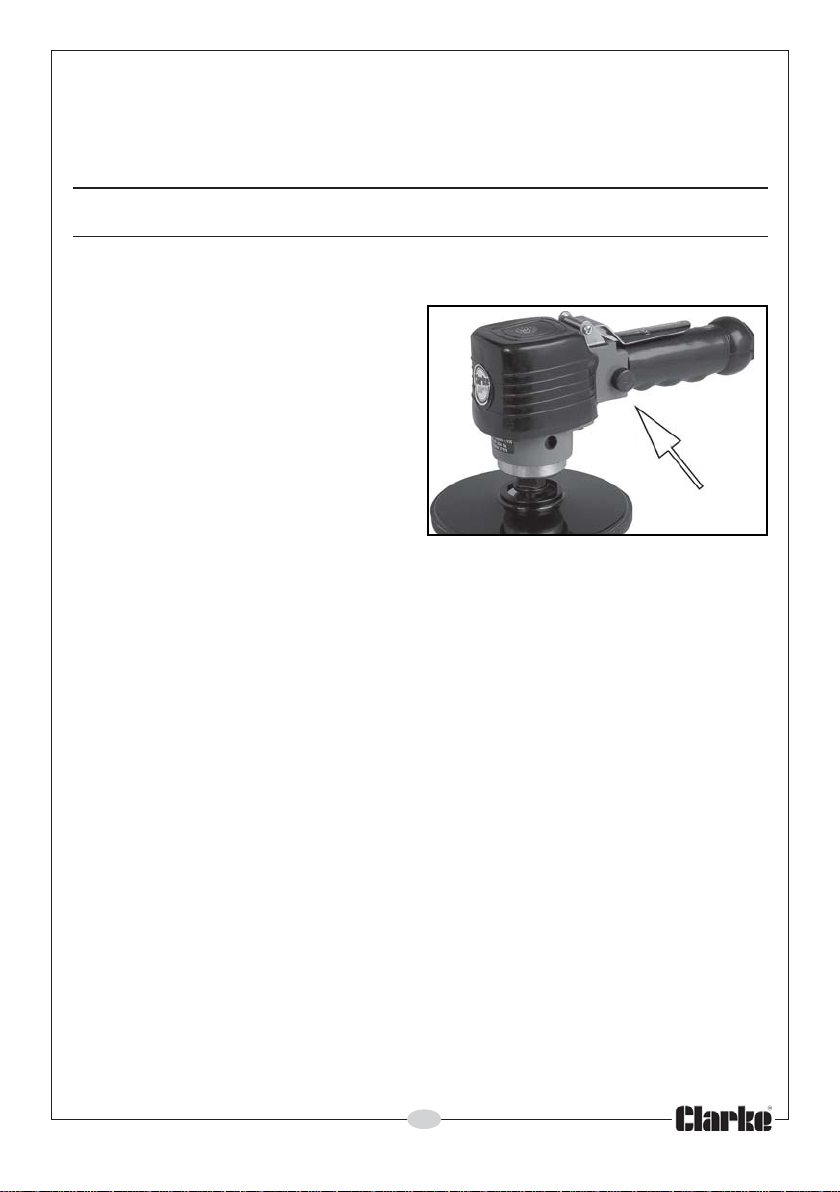
1. Adjust the operating speed if
required, by twisting the speed
control shown.
• Clockwise will increase the
sanding speed.
• Anticlockwise will decrease the
sanding speed.
2. Squeeze the trigger against the
body of the tool to start and
evaluate its speed.
3. Rest the disc pad on the workpiece and start the sander. Let the tool do
the work.
• The actual weight of the machine is normally sufficient for efficient
sanding. Do not put additional pressure on the machine, which would only
slow down the speed of the pad, reducing efficiency and placing an
additional burden on the motor.
4. Pass the sander back and forth in wide, overlapping areas, taking care to
keep the sander moving around at all times. Avoid dwelling in one place
for more than a moment.
5. Release the trigger to stop the tool.
6. Always ensure the tool has stopped before putting it down.
DISCONNECTING THE AIR SUPPLY
1. Do not disconnect the air supply hose until the compressor has been shut
down and the compressed air pressure released.
2. Once the pressure has been released, disconnect the air supply hose from
the tool.
STORAGE
1. Store the tool safely in its box in a dry, secure environment.
2. When storing, ensure the blanking plug is replaced on the airline
connector once the airline has been disconnected.
9
Parts & Service: 020 8988 7400/E-mail: [email protected] or [email protected]
Page 10
3. If the tool is not to be used for longer than 24 hours, run a few drops of
CLARKE airline oil into the air inlet and run the tool for a few seconds to
ensure that the oil has been well distributed throughout the tool.
TROUBLESHOOTING
MOTPMYS MELBORP NOITULOS
snurlooTlamronta
rednudaol.
wolssnurlooT
.tsuahxe
nwodswolstubdeeps
nacirbulfo
riA.yl
morfylthgilswolf
.selcitrap
.nrowstraprotoM.1
gnikcitsronroW.2
kcaloteudmsinahcem
.t
demmajstraprotoM.1
tridro/&mughtiw
luahrevo
.ssenilnaelc
rofrelaedotnruteR.1
.strapgnivom
liognitacirbullootriapirD.2
kaosdnatelniriaotni
rofretlifriatelnienimaxE.1
.no
itisop
riA.nurtonlliwlooT
morfyleerfswolf
.tsuahxe
.ffotuhstonlliwlooTsgnir-OelttorhT.1
ddetaeston
.laretam
desolcnirotalugeR.2
wolfrialareneG.3
.tridybdekcolb
kcutssenavrotoM.1
eud
ngieroffopudliubot
rodegama
..yltcerroc
.3yltneggnisuohrotompaT
tisop
.noi
.noitator
.yllaunam
otgnitarepoyrT.2
.noitator
pirD.4
.strap
nepootrotalugertsujdA.2
trohsnilootetarepO.3
esrever/drawroffostsrub
&ylppusriatcennocsiD.1
ylbmessalootetator
trohsnilo
esrever/drawroffostsrub
.tellamrebburhtiw
riafospordwefa
ehtotniliognitacirbulloot
gnivomkaosottelniria
nruterrognir-OecalpeR.1
.riaperrofrelaedekralCot
10
Parts & Service: 020 8988 7400/E-mail:[email protected] or [email protected]
Page 11
MAINTENANCE
WARNING! MAKE SURE THAT THE TOOL IS DISCONNECTED FROM THE AIR
SUPPLY BEFORE STARTING ANY CLEANING OR MAINTENANCE
PROCEDURES.
DAILY
• Drain water from the compressor
air tank and air-line.
• Pour a few drops of CLARKE air
line oil** into the air inlet. This
should be carried out regardless
of whether or not an air line
lubricator is used. If a lubricator is
not used, this procedure should
be repeated after every two to
three hours of use.
WEEKLY
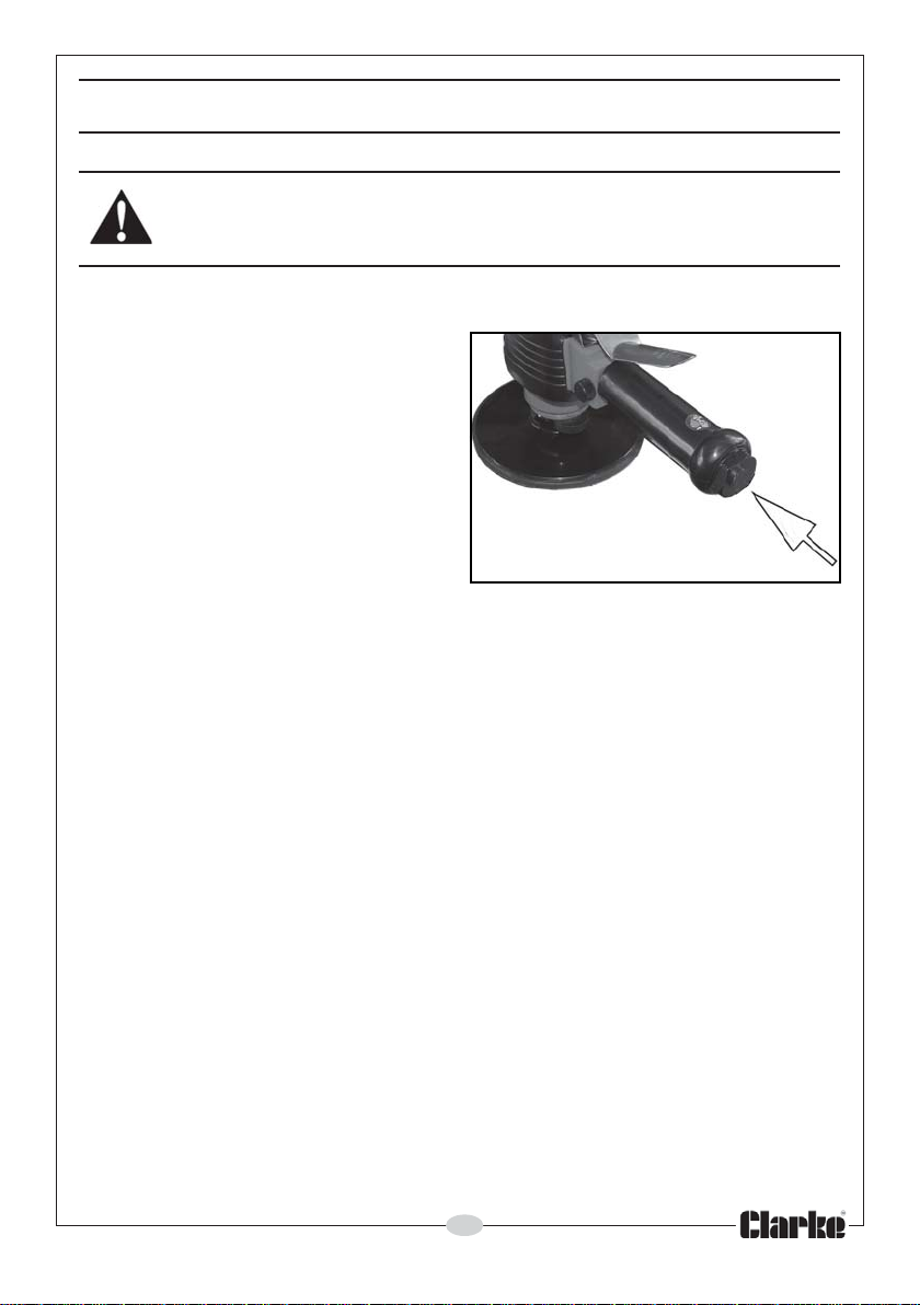
• Check the air inlet screen filter shown in Fig 4 and clean if necessary.
CLEANING
• Keep the body of the tool clean and free from debris. Grit or gum deposits
in the tool may reduce efficiency.
• After extensive use, remove the inlet screen filter and flush out the
mechanism with gum solvent oil or an equal mixture of SAE No10 oil and
paraffin. Allow to dry before use.
Air Inlet Screen
Filter (located
here)
SERVICE AND REPAIR
• Any major servicing and repairs should be carried out by your local
CLARKE dealer or a qualified service technician.
PERFORMANCE
Please note that factors other than the tool may effect its operation and
efficiency such as reduced compressor output, excessive drain on the airline,
moisture, or restrictions in the line, or the use of connectors of improper size or
poor condition which will reduce air supply.
**Clarke Airline Oil is available from your CLARKE dealer: part no 3050825.
11
Parts & Service: 020 8988 7400/E-mail: [email protected] or [email protected]
Page 12
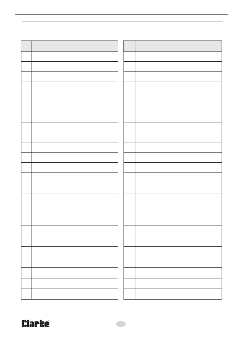
PARTS LIST
oN noitpircseD oN noitpircseD
1gnisuoHrotoM52llaB
2rotpadAesoH62rotoR
3gnirpSevlaVelttorhT72edalBrotoR
4tfahSevlaVelttorhT82tfahSrotoR
5g
6gniR-O03teksaG
7gniR-O13gnisuoHevirD
8ydoBevlaV23wercSpaC
9tuN.xeH33wercSpaC
01tekcarB43wercSpaC
11wercS53buHlatibr
21rehsaWkcoL63tuNxeH
31
41
51
61
71
81
91
02
12g
niR-O92yeK
tuNxeH73recapS
reveLelttorhT83kcoLeldnipS
revoCgnisuoH93rehsaWgnirpS
pilcriC04rehsaWta
gniR-O14)kcoLeldnips(wercSpaC
evlaVrotalugeR24wercSxeH
pilcriC34gniraeBllaB
rehsaWevaW44eldnipSevirD
niraeB54rehsaWgnirpS
O
lF
22
32rednilyC74daPgnidnaS
42gniR-O
Parts & Service: 020 8988 7400/E-mail:[email protected] or [email protected]
etalPdnE64gniRgniniiateR
12
Page 13
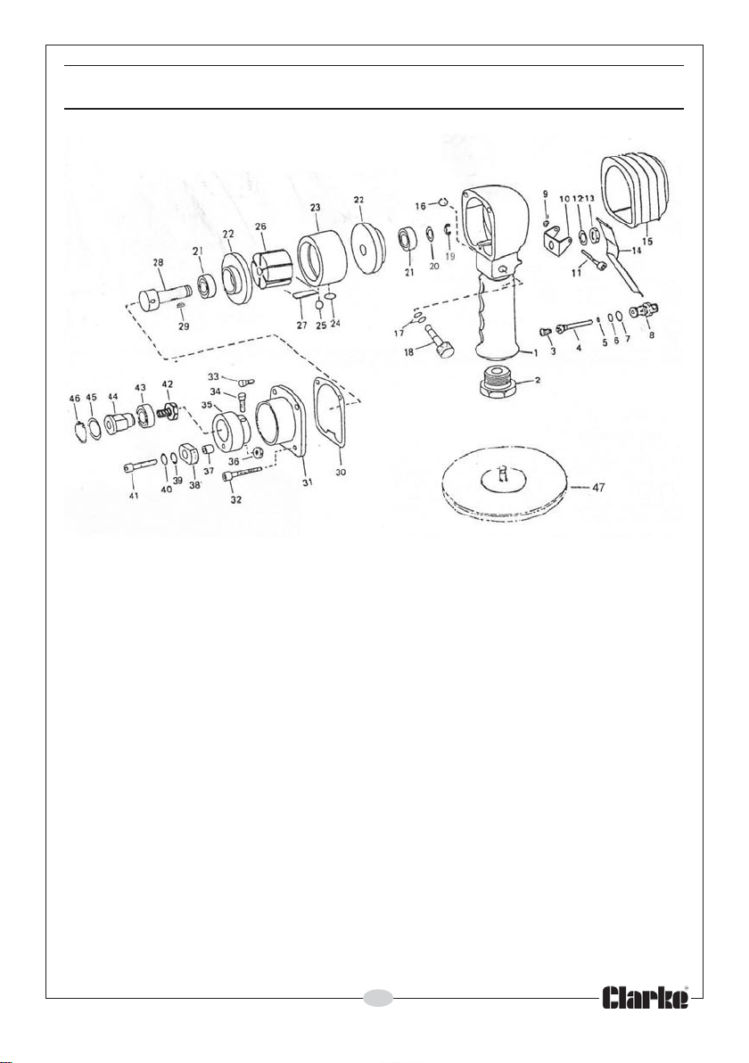
PARTS DIAGRAM
ABRASIVE DISCS
Replacement abrasive discs (self adhesive - 6” (150mm) dia) are available
from your CLARKE dealer:
Fine Part no. 6502097
Medium Part no. 6500809
Coarse Part no. 6502102
ACCESSORIES
A wide range of accessories are available including filter/regulators,
lubricators, high pressure hoses, etc. Contact your CLARKE dealer for further
information, or call CLARKE International on 01992 565333.
13
Parts & Service: 020 8988 7400/E-mail: [email protected] or [email protected]
Page 14
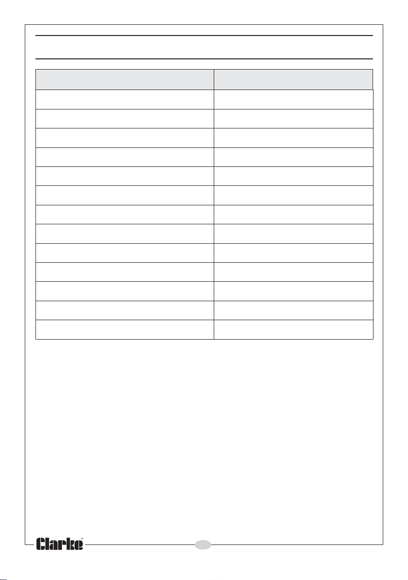
SPECIFICATIONS
erutaeF noitacificepS
noitpmusnoCriAlanimoNmfc6
erusserPriAgnitarepO)rab2.6(isp09
eziStelnIriAPSB"4/1
deepSmumixaMmpr
eziSesoHmuminiM)mm8("61/5
)BdABd09
L(leveLerusserPdnuoS
AP
)ABdawL(leveLrewoPdnuoSABd99
sleveLnoitarbiVces/M5.8
:k-eulavytniatrecnUs/m3.1
)enalpelgnis(gnidaerderusaemtsehgiHs/m80.3
)HxWxL(snoisnemiD )csidcxe(mm011x57x032
thgieWgk9.1
eziSdaPaid)mm051("6
0008
2
2
2
14
Parts & Service: 020 8988 7400/E-mail:[email protected] or [email protected]
Page 15
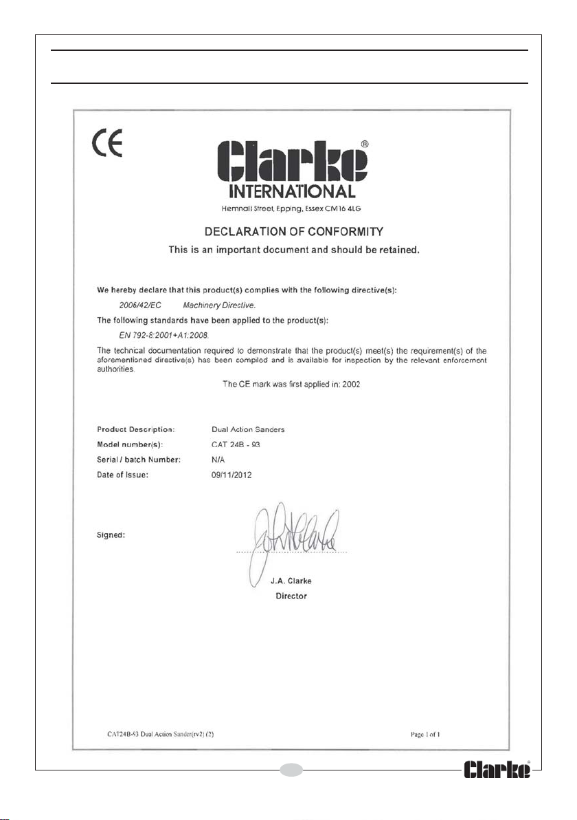
DECLARATION OF CONFORMITY
15
Parts & Service: 020 8988 7400/E-mail: [email protected] or [email protected]
Page 16
 Loading...