

Page 1
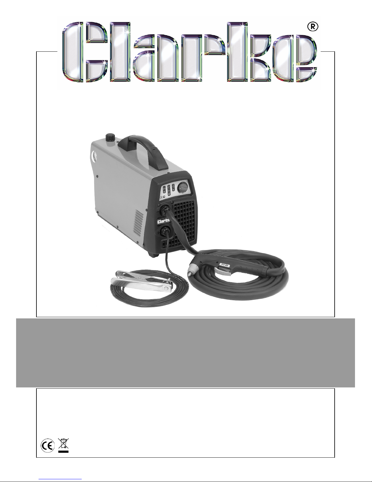
OPERATION & MAINTENANCE
INSTRUCTIONS
LS1208
PLASMA CUTTER
MODEL NO: 30SI
PART NO: 6016010
Page 2

2
Page 3

3
INTRODUCTION
Thank you for purchasing this CLARKE Plasma Cutter.
Before attempting to use this product, please read this manual thoroughly and
follow the instructions carefully. In doing so you will ensure the safety of yourself
and that of others around you, and you can look forward to your purchase
giving you long and satisfactory service.
GUARANTEE
This product is guaranteed against faulty manufacture for a period of 12
months from the date of purchase. Please keep your receipt which will be
required as proof of purchase.
This guarantee is invalid if the product is found to have been abused or
tampered with in any way, or not used for the purpose for which it was
intended.
Faulty goods should be returned to their place of purchase, no product can
be returned to us without prior permission.
This guarantee does not effect your statutory rights.
PARTS AND SERVICING
For Parts & Servicing, please contact your nearest dealer, or
CLARKE International, on one of the following numbers.
PARTS & SERVICE TEL: 020 8988 7400
PARTS & SERVICE FAX: 020 8558 3622
or e-mail as follows:
PARTS: [email protected]
SERVICE: [email protected]
Page 4

4
TABLE OF CONTENTS
INTRODUCTION................................................................ 3
GUARANTEE ..................................................................... 3
PARTS AND SERVICING ................................................... 3
TABLE OF CONTENTS........................................................ 4
SAFETY RULES AND GENERAL WARNINGS...................... 5
EMC.................................................................................. 6
SAFETY DEVICES............................................................... 7
SAFETY EQUIPMENT.......................................................... 8
SYMBOLS.......................................................................... 9
ELECTRICAL CONNECTIONS ........................................... 10
PRINCIPLES OF OPERATION ............................................ 11
PARTS IDENTIFICATION.................................................... 12
COMPRESSED AIR ............................................................ 13
ASSEMBLY ........................................................................ 13
USING THE PLASMA CUTTER ............................................ 14
POTENTIAL PROBLEM DURING USE.................................. 18
MAINTENANCE ................................................................ 19
TROUBLE SHOOTING........................................................ 21
SPECIFICATIONS .............................................................. 22
EXPLODED DIAGRAM & PARTS LISTS............................... 23
TORCH EXPLODED DIAGRAM & PARTS LIST.................... 24
WIRING DIAGRAM........................................................... 25
DECLARATION OF CONFORMITY.................................... 26
NOTES............................................................................... 27
Page 5
5
SAFETY RULES AND GENERAL WARNINGS
INTRODUCTION
Your plasma cutting unit is fitted with sophisticated safeguards which block
functioning and therefore the cutting operations until all the safety conditions
are present. The plasma cutting technique requires dangerously high voltage
for pilot arc starting and during cutting, therefore the following safety rules
must be observed with great care.
ELECTRICITY
1. Make sure that the unit is earthed and that the supply line has an
adequate earth connection.
2. Make sure that the work bench has a satisfactory earth connection.
3. Avoid contact between the metal bars being cut
and bare skin or damp
clothes.
4. Do not lean on the piece being cut or hold it in your hands.
5. Do not use in damp environments or on wet surfaces.
6. Do not use the unit if the tor
ch or cables appear damaged.
7. Always turn the unit off before replacing the electrode, the nozzle or the
spr
eader tip of the torch.
8. Always switch the unit off and remove the power cable from the mains
so
cket before carrying out any maintenance on the unit.
CAUTION: IF DURING THE CUTTING OPERATION A SLIGHT ELECTRIC
SHOCK IS FELT, STOP WORK IMMEDIATELY AND DO NOT USE THE UNIT
UNTIL THE FAULT HAS BEEN DISCOVERED AND RESOLVED.
CUTTING FUMES AND GASES
Harmful fumes and metallic powders are produced during the cutting
operation. Metals which are painted or coated or which contain mercury,
cadmium, zinc, lead and graphite may produce harmful concentrations of
toxic fumes during cutting.
To protect the operator or other persons from exposure to possible toxic fumes,
fume respirators should be worn and work areas should be adequately
ventilated.
Page 6
6
When working in enclosed environments, suction units should be fitted below
the cutting areas.
FIRE HAZARDS
1. Prevent sparks or hot scale from producing flames.
2. Remove inflammable or combustible materials from
the cutting area.
3. Make sure that fire-fighting equipment is located near the work area.
4. Situate the unit in an area where the air can be sucked in and exhausted
from the grilles on t
he pane
CAUTION: DO NOT CUT FUEL OR LUBRICANT CONTAINERS EVEN IF THESE
ARE EMPTY. DO NOT CUT CONTAINERS OR CASINGS WHICH CONTAIN
INFLAMMABLE MATERIAL.NEVER CUT IN ENVIRONMENTS WHICH ARE
POLLUTED BY INFLAMMABLE GAS OR COMBUSTIBLE LIQUID VAPOURS
(SUCH AS PETROL).
l.
EMC
Before installing the plasma cutting unit, carry out an inspection of the
surrounding area, observing the following guidelines:
1. Make sure that there are no other power supply cables, control lines,
tele
phone leads or other equipment near the unit.
2. Make sure that there are no radio receivers or television appliances.
3. Make sure there are no computers or other control systems.
4. Make sure that there is no-one with a pacemaker or hearing aid in the
a
rea around the unit.
5. Check the immunity of any other equipment operating in the same
environment. In certain cases additional protective measures may be
required.
CAUTION: WHEN HALOGENATED SOLVENTS OR DEGREASING AGENTS
ARE PRESENT, THE MATERIAL TO BE CUT SHOULD BE CLEANED PROPERLY
TO PREVENT THE FORMATION OF TOXIC GASES. SOME CHLORINATED
SOLVENTS MAY DECOMPOSE IN THE PRESENCE OF THE RADIATION
GIVEN OUT BY THE ARC AND MAY GENERATE PHOSGENE GAS.
Page 7

7
Interference can be reduced in the following ways:
1. If there is interference in the power supply line, an E.M.C. filter should be
inserted between the mains and the unit.
2. The output cables of the unit should be shortened; these should be kept
close together and stretched along the ground.
3. All the panels of the unit should be correctly closed after carrying out
maintenance.
SAFETY DEVICES
The plasma cutting units are supplied with the following safety devices:
THERMAL PROTECTION DEVICES
These are installed at the points most subject to high temperatures such as the
power transformers and the rectifying units. An amber light on the front panel
lights up when the thermal protection device intervenes.
A PNEUMATIC PROTECTION DEVICE
This prevents damage to the torch caused by having either no air supply or
low air pressure. An amber light on the front panel lights up when the
pneumatic protection device intervenes.
AN ELECTRIC SHOCK PROTECTION DEVICE
This prevents the operator from coming into contact with the live parts of the
torch (such as the electrode, etc.) This consists of a safety device, built into the
body of the torch, which breaks the main power circuit when the end part of
the torch is removed to replace the electrode or the tip.
When the electrical protection device intervenes, the unit is prevented from
operating.
Page 8
8
SAFETY EQUIPMENT
EYE AND BODY PROTECTION
One of the hazards during the welding/cutting process is the emission of
electromagnetic waves due to the electric arc. The length of these waves
ranges from infrared to ultraviolet. If these rays hit the eyes, they can cause
various complaints such as conjunctivitis, burns to the retina, deterioration of
sight, etc. Moreover a high concentration of ultraviolet rays can burn the skin.
It is, therefore, extremely important that the operator uses adequate safety
equipment and clothing, such as:
• Leather gloves
• Leather aprons
•Safety shoes
• Safety mask (or even better helmet) large enough to cover the
whole of the face, equipped with safety lenses able to filter all the
radiation and reduce the intensity of the light absorbed by the eye.
IMPORTANT: safety screens should be installed around the welding area to
protect other people, who may be working in adjacent areas, from the
radiation given out by the arc.
CAUTION: NEVER, UNDER ANY CIRCUMSTANCES, LOOK AT AN ELECTRIC
ARC WITHOUT EYE PROTECTION.
CAUTION: A FURTHER HAZARD FOR EYES IS THE RISK OF SPLINTERS OR
PARTICLES WHICH MAY BE DETACHED DURING THE CUTTING
OPERATIONS OR DURING GRINDING, BRUSHING OR HAMMERING AWAY
OF THE SCALE.ALWAYS WEAR GOGGLES OR PROTECTIVE SHIELDS WITH
TRANSPARENT LENSES DURING THESE OPERATIONS TO PREVENT
SPLINTERS OR OTHER FOREIGN BODIES FROM ENTERING THE EYE.
Page 9
9
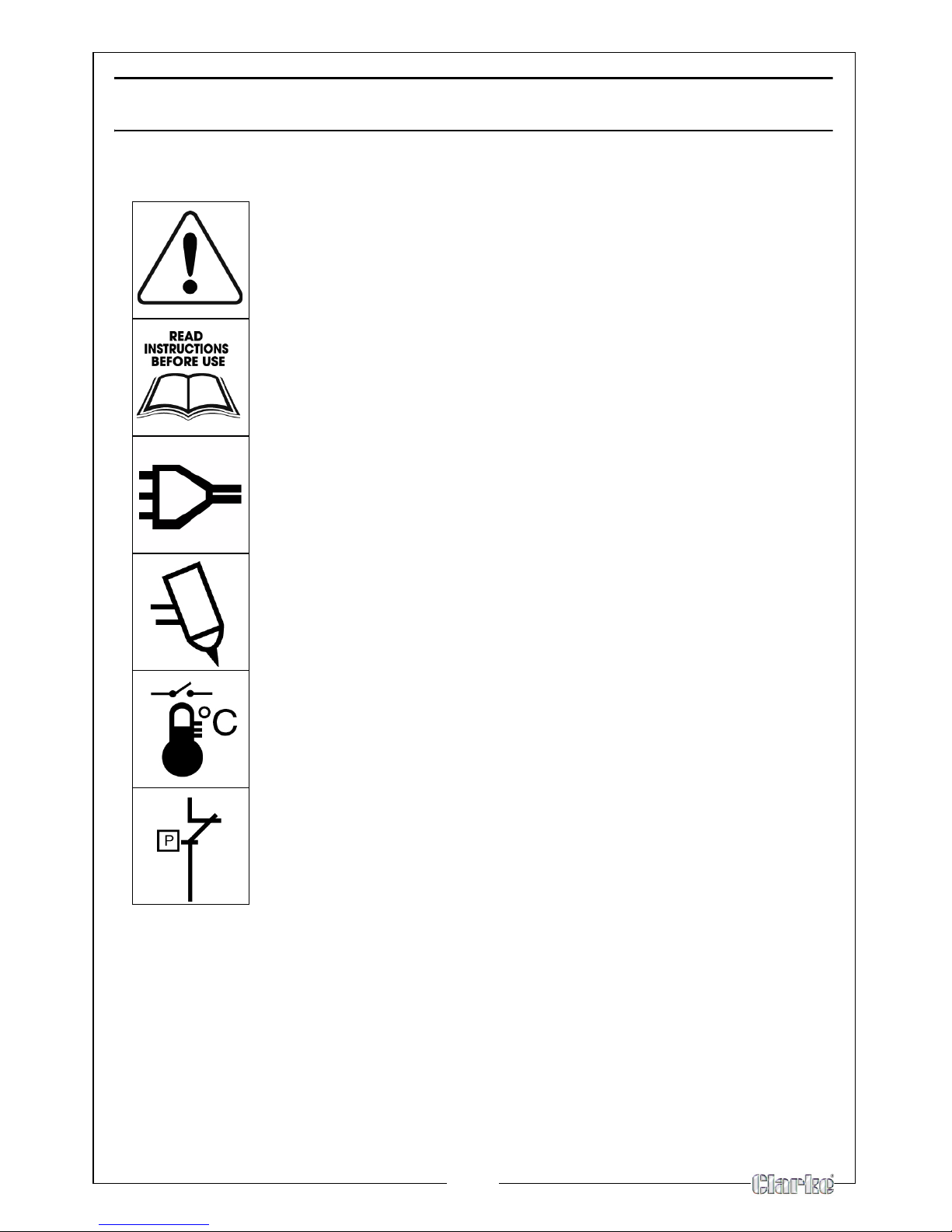
SYMBOLS
The following symbols appear on your Plasma Cutter:
Caution
Read the Instruction Manual
Mains Supply
Plasma Cutting
Thermal Protection Device
Under Pressure Protection Device
Page 10
10
ELECTRICAL CONNECTIONS
Connect the mains lead, through a suitably fused isolator switch, to a 230 Volt
(50Hz) electrical supply, with a fuse rating in accordance with the
specifications. A standard 13 Amp plug MUST NOT be used with these welders.
IMPORTANT: The wires in the mains lead are coloured in accordance with the
following code:
Green & Yellow - Earth
Blue - Neutral
Brown - Live
• Connect GREEN & YELLOW cord to terminal marked with a letter “E” or
Earth symbol “ ” or coloured GREEN or GREEN & YELLOW.
• Connect BROWN cord to terminal marked with a letter “L” or coloured
RED.
• Connect BLUE cord to terminal marked with a letter “N” or coloured
BLACK.
We recommend that this machine is connected to the mains supply via a
Residual Current Device (RCD)
If in any doubt, DO NOT attempt any connections or repairs yourself. Consult
a qualified electrician, your local Clarke dealer or Clarke International on:
020 8988 7400 or e-mail [email protected]
CABLE EXTENSION
Always use an approved extension cable suitable for the power rating of this
tool (see specifications), the conductor size should also be at least the same
size as that on the machine, or larger. When using cable reel, always unwind
the cable completely
.
WARNING: THIS APPLIANCE MUST BE EARTHED
IMPORTANT
If a cable extension is needed, it is essential to comply with the following data.
Voltage Extension length Cable section
230V up to 20 Meters
2.5mm
2
230V 20 - 50 Meters
4mm
2
Page 11

11
PRINCIPLES OF OPERATION
WHAT IS PLASMA CUTTING
Plasma Cutting is a fast, clean and distortion free, means of cutting through all
types of metal from mild and stainless steels to aluminium brass and copper.
• An inert gas (compressed air) is blown at high speed out of the
nozzle; whilst at the same time an electrical arc travels through the
gas heating it to an extremely high temperature, this ionizes the gas.
• The column of heated ionized gas is called “Plasma” and is a good
conductor of electricity.
• The cutting procedure utilises the plasma to transfer the electric arc
to the metal workpiece, which is melted by the heat and then
blown out of the way using the compressed air supply.
HOW THE PLASMA CUTTER WORKS
• The start of the cycle is determined by an arc, called the pilot arc,
which is struck between the electrode (negative polarity) and the
torch nozzle (positive polarity) due to the short circuit between these
two elements.
NOTE: The duration of the pilot arc is set in the factory at 3 seconds; if
the transfer has not been made within this time, the cycle is
automatically stops.
• When the torch is brought into direct contact with the workpiece
(connected to the positive polarity of the power source) the pilot arc is
transferred between the electrode and the workpiece itself thus
striking a plasma arc, also called cutting arc.
Page 12
12
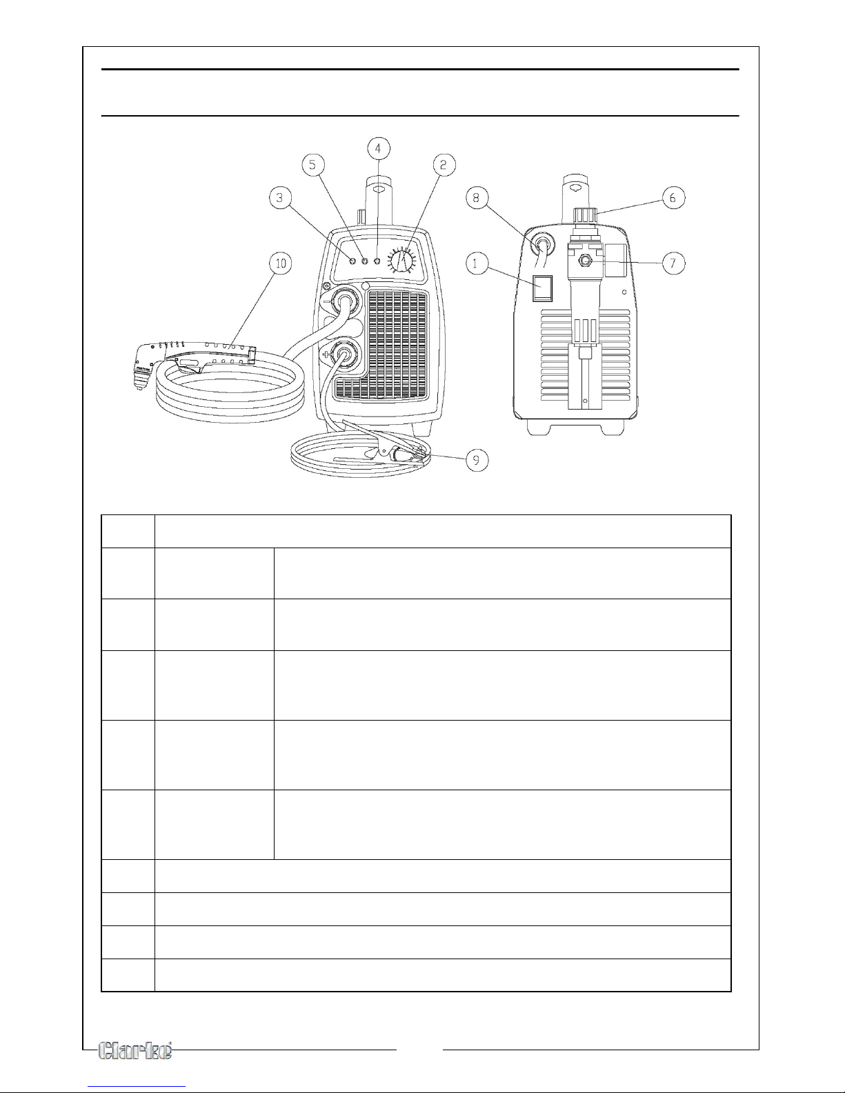
PARTS IDENTIFICATION
1 ON/OFF Switch
2 Output
current kno
b
Adjusts the cutting current supplied by the machine
according to the thickness of material/speed.
3 Green LED Turns ON when input voltage is applied
blinks slowly when voltage goes above 260V, or below 180V.
4 Red LED Turns ON when torch is triggered. Blinks qu
ickly during 3 second
safety pre-flow prior to pilot arc ignition. Blinks slowly if
cutting arcs not initiated after 3 second pilot arc ignition.
5 Yell ow L ED ON when the thermal protection is activated.
Blinks slowly when the under pressure protection is working
(the
pressure is less than 3,8 Bar).
6 Air regulator Adjusts the input air pressure - pull upward to unlock -
no
minal air pressure setting is 4,5 Bar.
Note: the regulator should never be set above 6 Bar.
7 Compressed air connection
8 Input cord
9 Work cable with clamp
10 Torch (with a trigger security cap)
Page 13
13
COMPRESSED AIR
A source of clean, dry air or nitrogen must be supplied to your plasma cutting
unit. The supply pressure must be:
• Between 72.5 and 150 psi (5 and10.3 bar).
• The supply must also have a flow rate of approximately 3.5 cu.ft./
min. (100L/min.).
• The unit will not operate if the input air pressure is below 55 PSI, 3.8
Bar
Failure to observe these precautions could result in excessive operating
temperatures or damage to the plasma cutter.
REGULATOR
An air regulator is included with the unit with an optimum pressure setting of 65
PSI, 4.5 Bar.
NOTE: The regulator should never be set above 6 bar.
NOTE: The drain knob (bottom of air regulator) should be closed during
cutting operations.
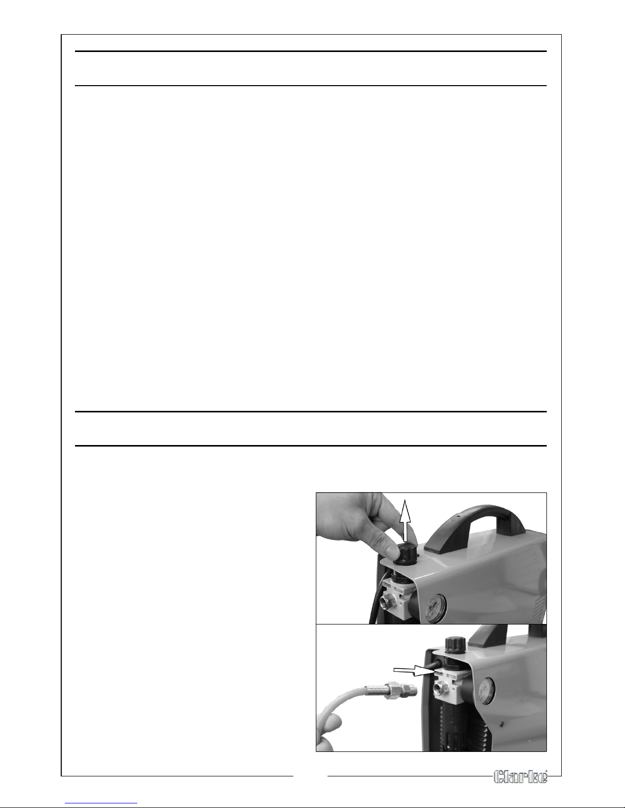
ASSEMBLY
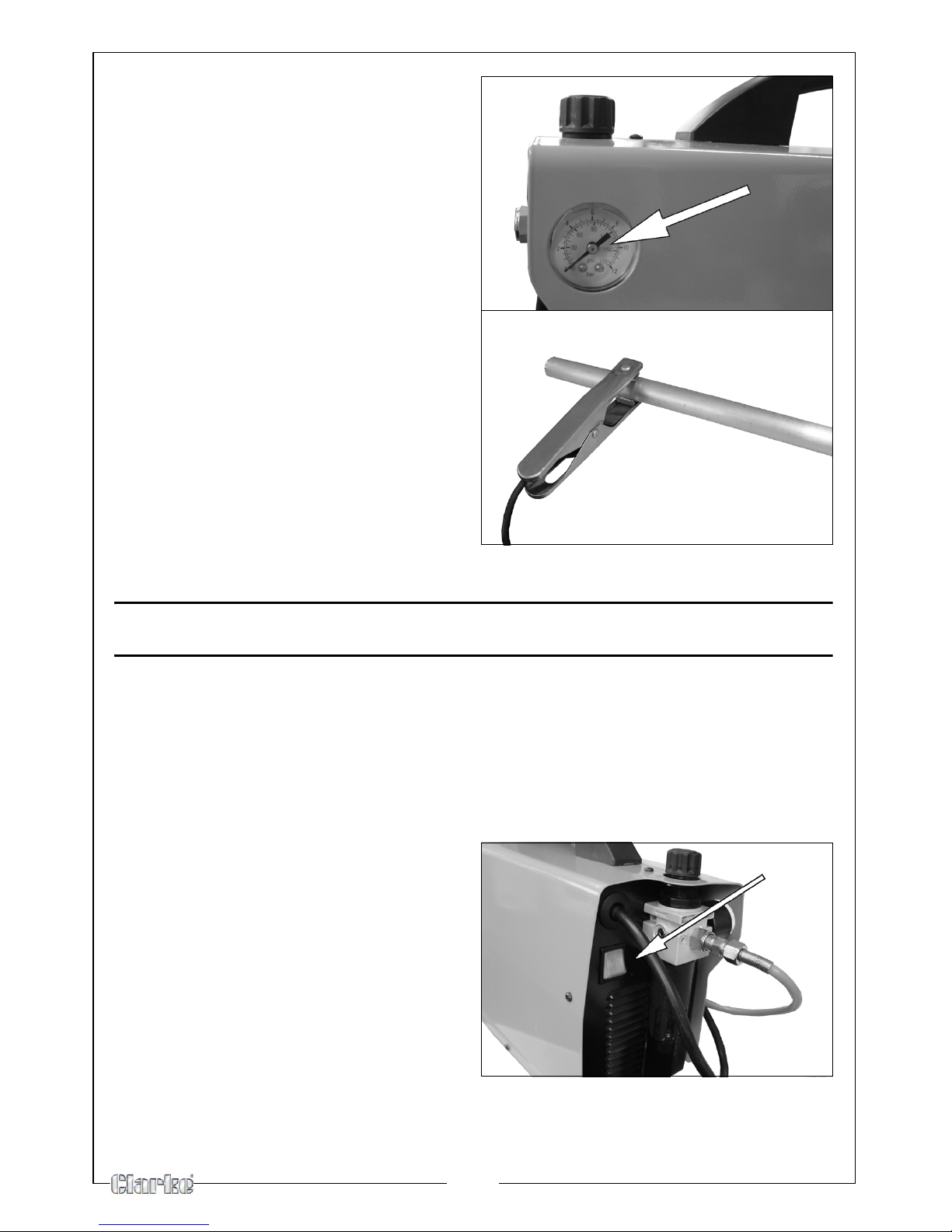
1. Connect the power supply cable to a mains socket.
2.
Pull out the regulator knob, and
turn it fully clockwise.
• This ensures the air regulator is
set to minimum
.
3. Connect the compressed air
supply as shown.
4. Turn the compressed air
su
pply ‘ON’
Page 14
14
5. Turn the air regulator (on the
plasma cutter) anticlockwise
to
a pressure of 4.5 bar.
6. When the pressure is set, lock the
knob in p
osition, by pushing it in.
7. Fasten the earth clamp to the
workpiece. If a metal bench is
being used, make sure it has also
been connected to earth.
• If the surface of the piece to be
cut is painted, rusty or covered
with insulating material, clean
the surface so that satisfactory
contact between the
workpiece and the earth
clamp can be obtained.
USING THE PLASMA CUTTER
• The torch can be comfortably held in one hand or steadied with two
hands. Choose the technique that feels most comfortable and
allows good control and movement. Position the index finger or
thumb to press the control switch on the torch handle.
SWITCHING ON/OFF
1. Switch the plasma cutter ON using
the ON/OFF switch.
• The Green LED will light up on
the control panel.
Page 15
15
CUTTING
1. With the torch in starting position, activate the torch trigger button.
• The unit will initiate gas purge (pre-flow)
to remove any
condensation that has accumulated in the torch
• When the gas purge is complete, pilot arc will come on and stay on
until the main cutting arc starts.
• If cutting arc has not started after 2-3 seconds. The pilot arc will go
out. The trigger should be released and pressed again to relight the
pilot arc.
2. Once on, the main cutting arc remains on as long as
the trigger is held
down, unless the torch is withdrawn from the work or torch motion is too
slow. Keep moving while cutting.
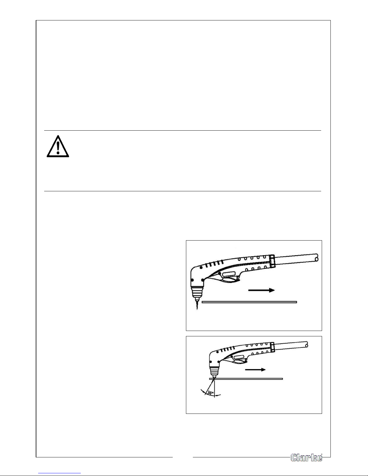
FOR EDGE STARTS
Hold the torch perpendicular to the
workpiece with the front of the tip on
the edge of the workpiece at the
point where the cut is to start.
FOR DRAG CUTS
Keep the torch in contact with the
w
orkpiece. For standoff cutting hold
the torch 2-3 mm from the work.
3.
Cut at a steady speed without
pausing. Maintain the cutting
sp
eed so that the arc lag is about
30° behind the travel direction.
4. If the cutting arc is interrupted,
and the tor
ch trigger remains
pressed, the pilot arc comes back
on automatically for 3 seconds.
CAUTION: AVOID UNNECESSARY LIGHTING OF THE PILOT ARC, TO
PREVENT EXCESSIVE CONSUMPTION OF THE ELECTRODE AND NOZZLE.
CAUTION: BECAUSE THESE MODELS ARE FITTED WITH A PILOT ARC,
CUTTING CAN COMMENCE EVEN ON METAL WHICH IS PAINTED OR
COATED. HOWEVER, DO BE AWARE THAT FUMES MAY BE GIVEN OFF BY
BURNING PAINT OR COATED SURFACES.
Page 16
16
PIERCING WITH A HAND TORCH
NOTE: Recommended maximum piercing capacity is 2mm. If you need
to make a cut on a metal sheet which has a sickness of more than
2mm without an edge start, make a hole ø 6mm using an electric
drill before you start cutting.
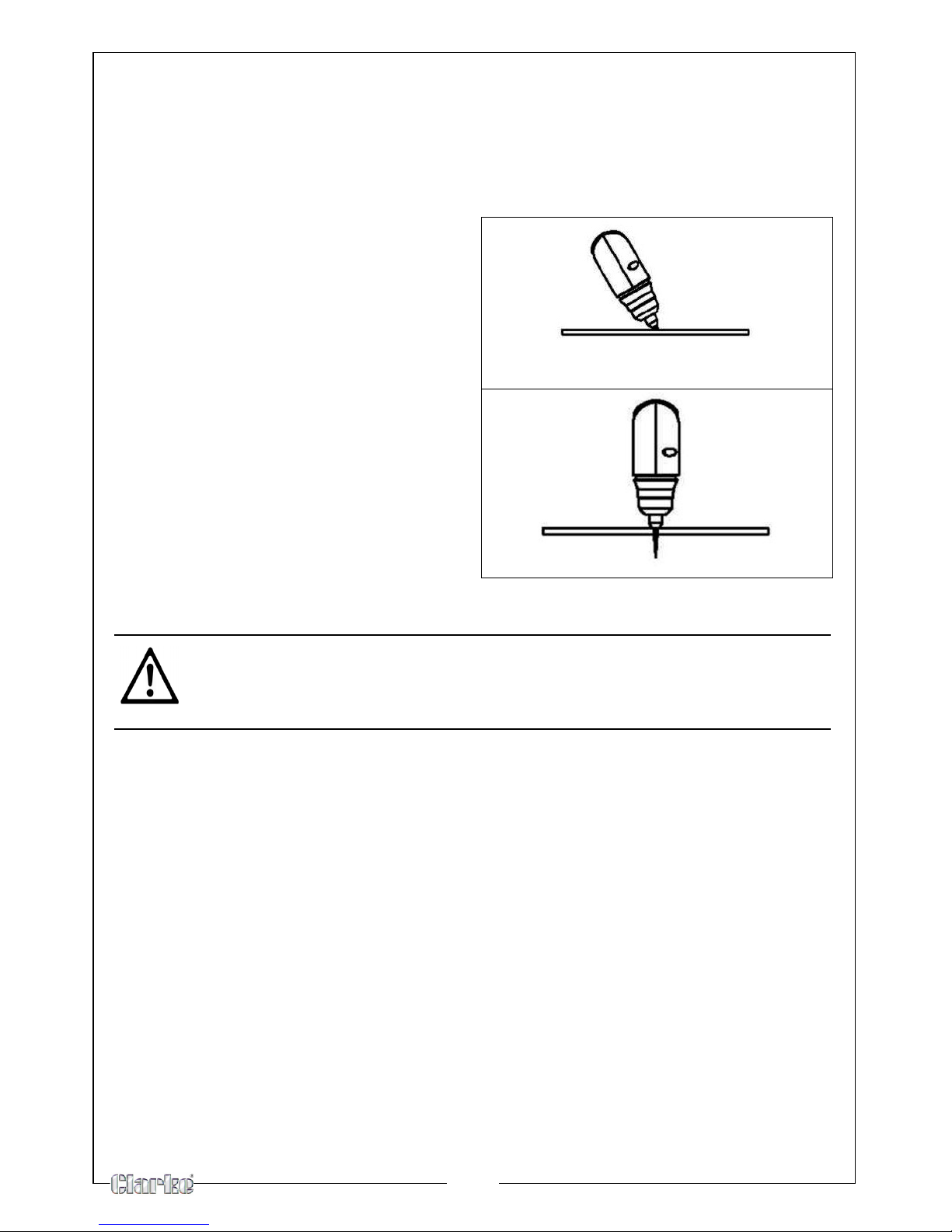
1. When piercing, tilt the torch
slightly so that blowback particles
blow away from the operator and
torch.
2. Complete the piercing off the
cutting line and then continue the
cut
onto the line. Hold the torch
perpendicular to the workpiece
after the cut is complete.
3. Clean spatter and scale from the
shield cup and the tip as soon as
possible. Spraying or dipping the
shield cup in anti-spatter
compound will minimize the amount of scale which adheres to it
CAUTION: SPARKS FROM THE CUTTING PROCESS CAN CAUSE DAMAGE
TO COATED, PAINTED, AND OTHER SURFACES SUCH AS GLASS, PLASTIC
AND METAL
NOTE: Handle torch leads with care and protect them from damage.
Page 17
17
SHUTTING OFF THE PLASMA CUTTER
• To stop cutting remove the torch from the workpiece. To extinguish
the pilot arc release the trigger.
NOTE: When the trigger is released, compressed air will continue to flow
for a short period of time, in order to cool the torch. Do not switch
off the machine until the air has stopped flowing or damage may
occur to the torch.
WARNING: WHEN YOU LIFT THE TORCH AWAY FROM THE WORKPIECE THE
CUTTING ARC WILL BE LOST BUT THE PILOT ARC WILL REMAIN IGNITED IN
THE NOZZLE UNTIL THE TORCH TRIGGER IS RELEASED.
WARNING: NEVER TOUCH THE NOZZLE WHILST THE PILOT ARC IS IGNITED
AS THIS MAY RESULT IN SERIOUS INJURY.
Page 18

18
POTENTIAL PROBLEM DURING USE
Insufficient
penetration
1. Cutting speed too high.
2. Torch is tilted.
3. Workpiece is too thick.
4. Cutting current is too low.
5. Torch parts are worn out.
Interruption of the
c
utting arc
1. Cutting speed too slow;
2. Excessive distance between torch and workpiece;
3. AC line too low - reduce output current;
4. Torch parts are worn out;
5. Non-genuine manufacturer's parts;
6. Work cable is disconnected;
Excessive scoria
settlement
1. Too low cutting speed (bottom dross);
2. Too high cutting speed (top dross);
3. Excessive distance between torch and workpiece;
4. Cutting current too low;
5. Torch parts are worn out;
6. Non-genuine manufacturer's parts;
Tilted cutting 1. Torch position not correct;
2. Asymmetric wear of nozzle hol
e and/or wrong assemblage
of the torch parts;
Excessive wear of
t
he nozzle and
electrodes
1. Air pressure too low;
2. Exceeding system capability (material too thick);
3. Contaminated air (hum
idity-oil);
4. Excessive pilot arc ignitions in the air;
5. Improperly assembled torch;
6. Torch tip contacting workpiece;
7. Damaged or loose torch head components;
8. Non-genuine manufacturer's parts.
Page 19
19
MAINTENANCE
CAUTION: BEFORE PERFORMING ANY MAINTENANCE ON THE PLASMA
CUTTER LET IT COOL.
TORCH
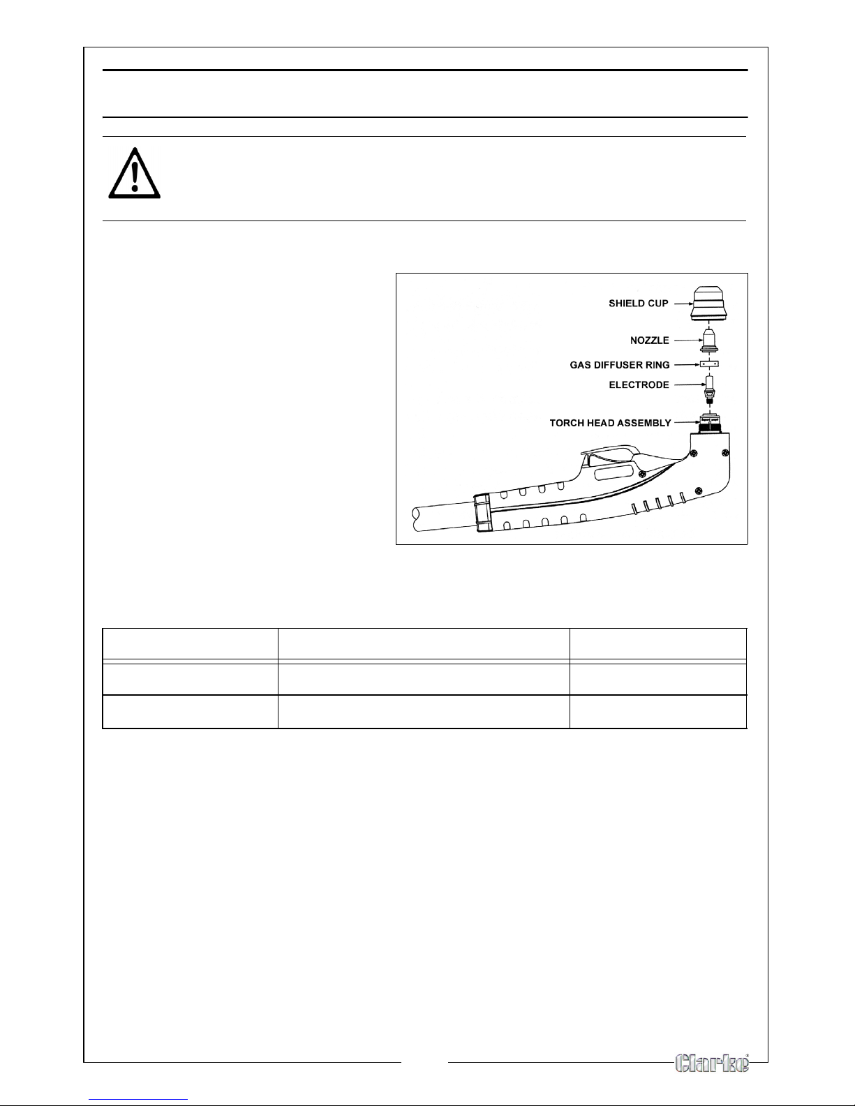
To replace the consumables in
the torch:
1. Unscrew the shield cup from
the tor
ch head assembly.
• Clean the shield cup
thor
oughly and replace if it
is damaged (burns,
distortions or cracks).
2. Remove the nozzle, gas
diffuser ring and electrode.
• Always replace the nozzle,
gas diffuser ring and
electrode at the same time
3. Fit a new nozzle, gas diffuser ring and electrode.
NOZZLE DIAMETER THICKNESS OF MATERIAL BEING CUT OUTPUT CURRENT
0.80 mm > 5mm 20-30 Amps
0.65 mm < 5mm 10-20 Amps
4. Replace the shield cup and ensure that it is secure.
IMPORTANT: Make sure that you do not cross tread the shield cup when you
reassemble the torch.
UNIT
• Keep the area around the machine clean and free of combustible
materials.
• Do not allow debris to collect, this could obstruct air flow to the
machine.
• Inspect the unit every 3-4 months (depending on how often the unit
is used) and use compressed air to remove any dust deposits.
Page 20
20
TORCH BODY, HANDLE AND CABLE
These parts need no particular maintenance with the exception of a periodic
inspection and cleaning
To keep the torch and the cable in good working order it is necessary to follow
these precautions:
• DO NOT use solvents or strong detergents when cleaning the plasma
cutter.
• If there is damage to the insulation such as breaks, cracks and burns
or even a loosening of electric conductors, the torch must not be
used.
• DO NOT touch torch and cable with warm or hot parts.
• DO NOT strain the cable.
• DO NOT move the cable on sharp edges or abrasive surfaces.
• DO NOT step on the cable.
• All repairs must be carried out buy a qualified service engineer.
COMPRESSED AIR FILTER
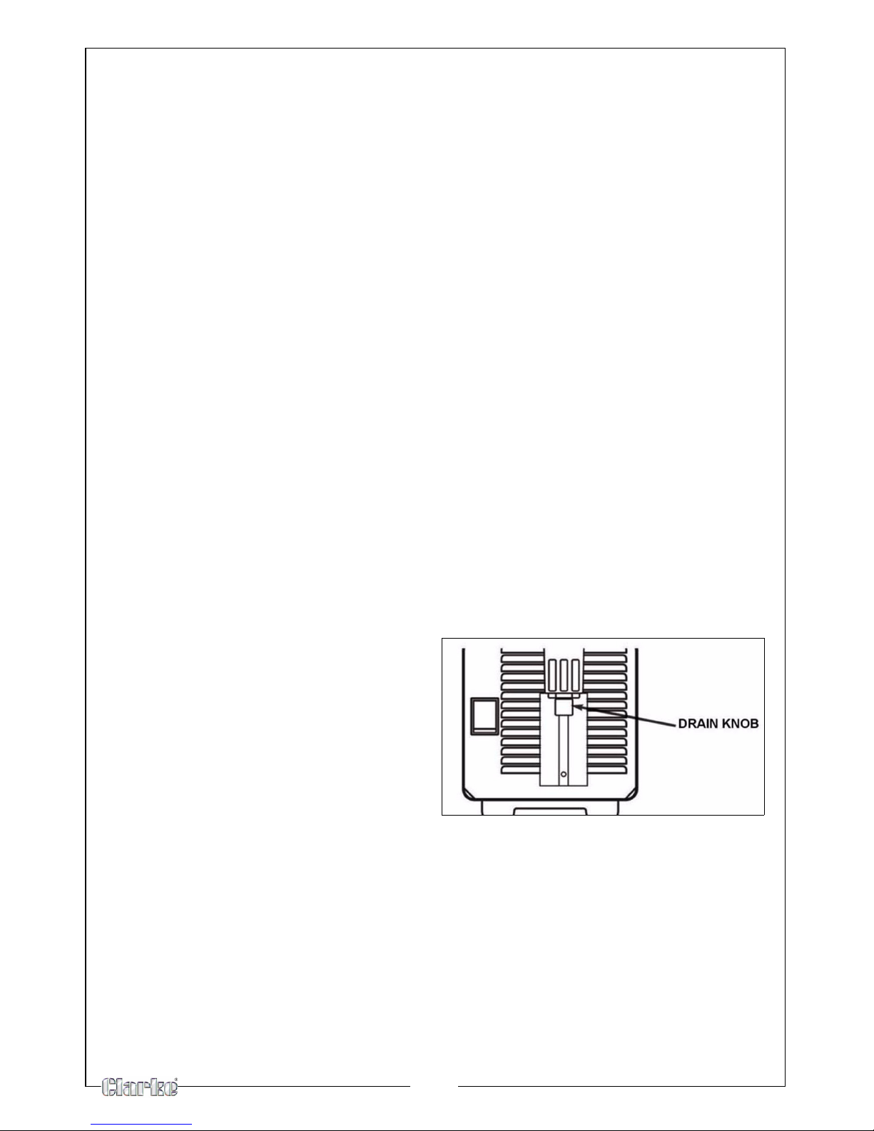
The unit is equipped with a filter for the compressed air. This filter is fitted with a
knob for the manual drain of the condensation. Purge periodically to remove
the water/oil in the filter by following the instructions below.
MANUAL PURGE
• Oil in the air is a severe problem
and must be avoided.
• The unit is equipped with an air
filter which captures water and
oil vapor.
• The vapor collected can be
drained out by turning the drain
knob located on the bottom of
the air filter.
The drain knob has 3 positions: -
Open, Automatic (Open when no air pressure, closed when air pressure.) or
closed
The drain knob should be closed during cutting operations (position 2 or 3).
REPLACING THE AIR FILTER
The air filter and air filter cartridge can only be replaced by a qualified service
engineer, contact your nearest Clarke service department See page 3.
Page 21

21
TROUBLE SHOOTING
GREEN LED OFF
Fan not operating.
No Input Power.
1. Plug unit into 230V outlet.
2. Reset breaker.
GREEN LED ON
YELLOW LED ON
Unit is overheating.
1. Make sure the unit has not been
op
erated beyond duty cycle limits.
2. Air flow obstructed.
GREEN LED ON
YELLOW LED FLASHES
No air flow in purge or pre-flow.
1. Air not connected or pressure too
low. Check
source for at least 5 Bar
(72.5 PSI) during purge or pre-flow,
adjust air pressure to 4,5 Bar (65 PSI).
2. Air filter or air line blocked, torch
blocked. Co
ntact your clarke
service department to replace the
filter cartridge. Check that air line
and torch leads are free of twists
and kinks.
GREEN LED ON,
YELLOW LED OFF,
No air flow when torch switch pressed.
1. Shield cup not properly installed
o
n torch. Check that shield cup is
fully seated against torch.
2. Faulty Torch Switch.
3. Faulty Main PC Board Repair /
Repl
ace Power Supply.
GREEN LED ON,
YELLOW LED OFF.
Air flows, Pilot arc does not start.
1. Faulty torch parts. Inspect torch
p
arts and replace if necessary.
2. Gas pressure too high. Set pressure
to
65 psi (4.5 BAR).
3. Faulty main PC Board. Repair /
replace.
Torch has pilot arc but does not cut. 1. Work lead not connected. Make
su
re work lead is connected
securely to bare metal.
2. AC input power too low. Use
shorte
st distance to breaker panel
possible.
3. Faulty Main PC Board. Repair/
Repl
ace.
Page 22
22
SPECIFICATIONS
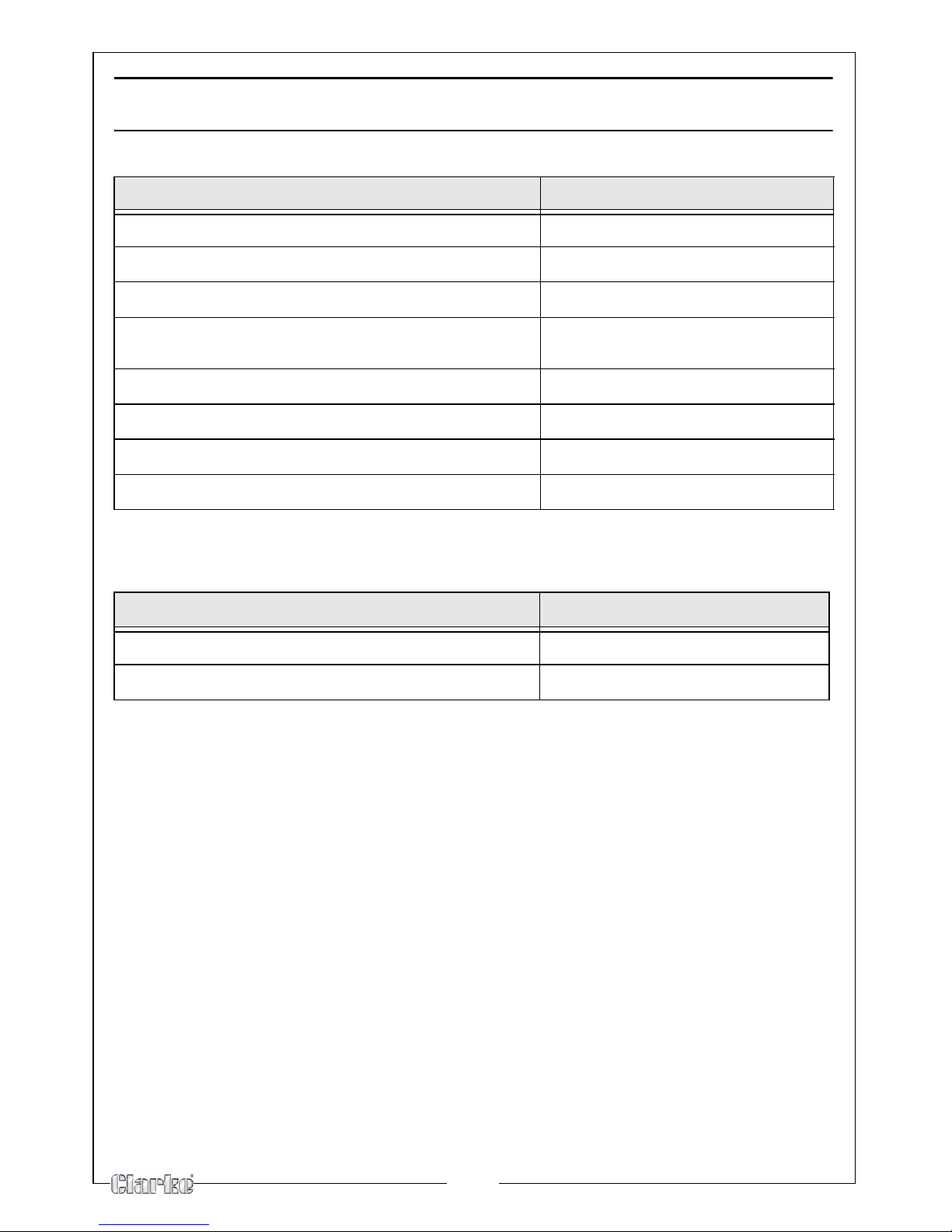
Power supply 230V 50Hz 1Ph
Input Current (MAX) 21 A
Output current (MIN-MAX) 12A - 28A
Maximum cutting depth Steel - 10 mm
Aluminium - 10 mm
Protection Class IP22
Weight 9.6 kg
Dimensions L x W x H 430 x 155 x 315 mm
Part No.
6016010
Please note that the details and specifications contained within, are correct
at the time of going to print. However, CLARKE International reserve the right
to change specifications at any time without prior notice.
Duty Cycle
Current
30% 28 Amps
100% 12 Amps
Page 23
23
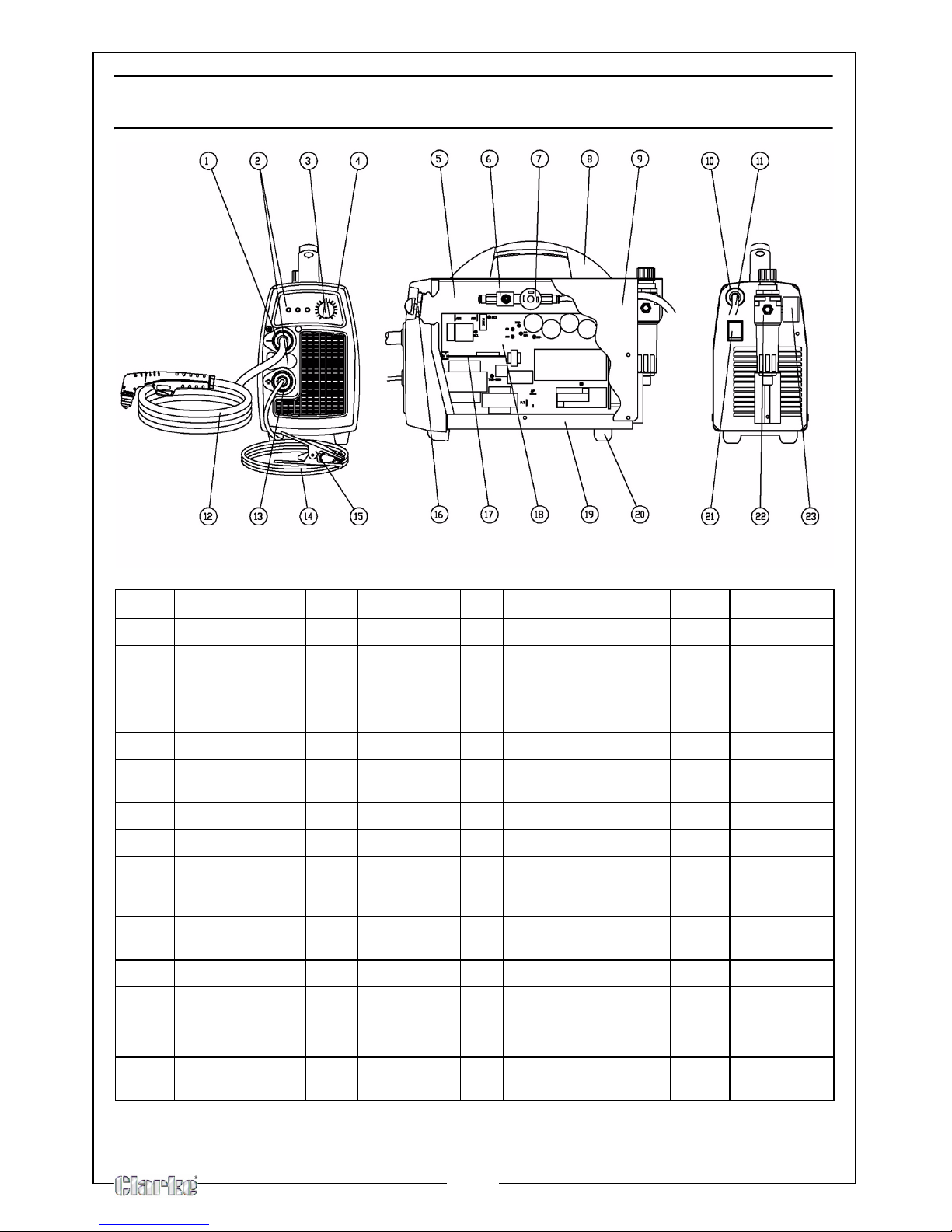
EXPLODED DIAGRAM & PARTS LIST
NO DESCRIPTION QTY PAR T N O NO DESCRIPTION QTY PAR T N O
1 CABLE CLAMP 1 EM21605040 12 PLASMA TORCH 1 EM23010070
1 NUT FOR CABLE
CLAMP
1 EM21605041 13 CABLE CLAMP + NUT 1 EM21605039
2 REGULATION
PLA
TE
1 EM77650146 14 EARTH CABLE 1 EM43210150
2 ADHESIVE LABEL 1 EM77650147 15 EARTH CLAMP 1 EM22110007
3 POTENTIOMETER
KNOB
1 EM21690308 16 PCB FRONT PANEL 1 EM22735213
4 UPPER PANEL 1 EM21690523 17 PCB 1 EM42735123
5 DIVIDING PANEL 1 EM33620166 18 PCB 1 EM42735119
6 ELET.5313 230V
BRK 1
/8" 3V DN
2,5 VITON
1 EM22900012 19 REAR PANEL 1 EM33700270
7 PRESSURE
SWITCH
1 EM22900016 20 LITTLE FEET 1 EM21610019
8 PLASTIC HANDLE 1 EM21600030 21 DOUBLE POLE SWITCH 1 EM22200043
9 COVER PANEL 1 EM33705505 22 FILTER 1 EM22905079
10 CABLE CLAMP +
SCREW
1 EM04600234 23 FILTER GUAGE 1 EM22905080
11 PVC INPUT
CABLE
1 EM20220020
S
Page 24
24
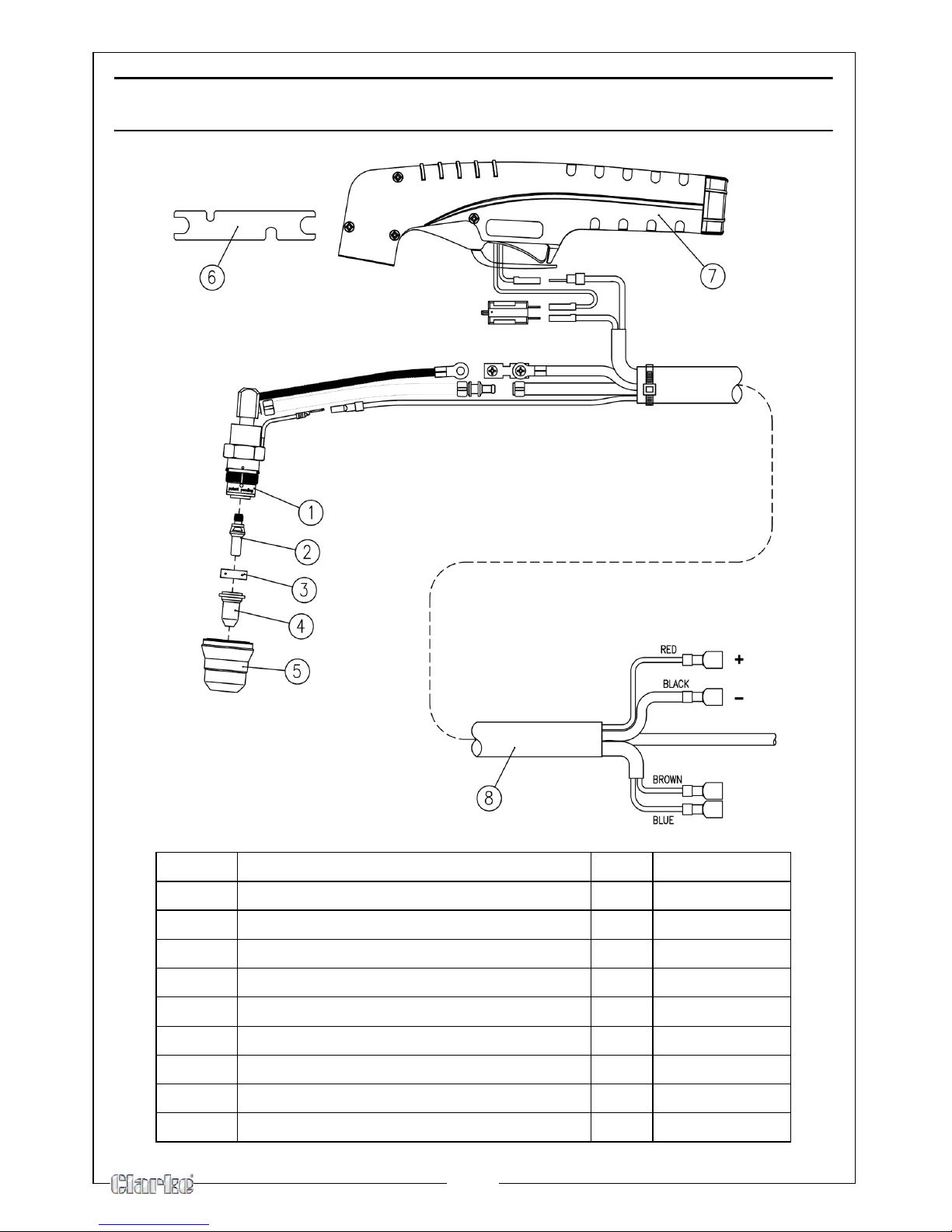
TORCH EXPLODED DIAGRAM & PARTS LIST
NO DESCRIPTION QTY PAR T N O
1
TORCH HEAD PLASMA PT-40
1 EM23015190
2
ELECTRODE FOR PT-25C-40-60 52582
1 EM23015187
3
AIR DIFFUSER
1 EM23015179
4
TIP D.0,8 (20-30A)FOR PT-40
1 EM23015186
4
TIP D.0,65 (10-20A)FOR PT-40
1 EM23015189
5
OUTSIDE PROTECTION NOZZLE (6 HOLES)
1 EM23015188
6
WRENCH FOR ELECTRODE
1 EM23015193
7
HANDLE + MICROSWITCH
1 EM23015184
8
CABLE ASSEMBLY
1 EM23015202
Page 25
25
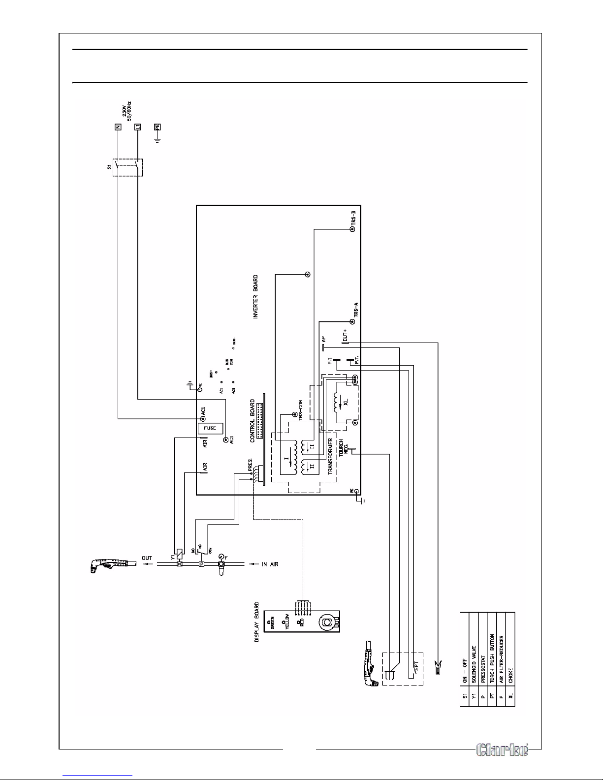
WIRING DIAGRAM
Page 26

26
DECLARATION OF CONFORMITY
Page 27

27
NOTES
Page 28

 Loading...