

Page 1
use &
maintenance
MANUAL
GB
RotarRotar
Rotar
RotarRotar
Cube SDCube SD
Cube SD
Cube SDCube SD
Rotar Cube SD 5-7-10 - Cod.197CC5200 Ed.1 - 07/2009
Page 2

Page 3

GENERAL INFORMATION
GENERAL INFORMATION ............................................................................. 3
SAFETY INDICATIONS ................................................................................. 4
INSTALLATION.............................................................................................. 6
TECHNICAL FEATURES ............................................................................... 7
CONTROLS AND SETTINGS ........................................................................ 8
ALARMS ..................................................................................................... 10
START-UP .................................................................................................... 11
OPERATION ............................................................................................... 12
MAINTENANCE .......................................................................................... 13
TROUBLE SHOOTING ................................................................................ 16
WIRING DIAGRAM ..................................................................................... 17
GB
OUTFIT
The following accessories are supplied with the compressor:
• user’s guide
• anti-vibration elements
• electric box key
• oil/condensate exhaust tube
Check that the above accessories are available. Once the goods have been delivered and accepted, no complaints are
accepted.
CONDITION OF THE MACHINE WHEN SUPPLIED
Every compressor is shop tested and delivered ready to be installed and to be set at work.
Oil used is: ROTENERGY PLUS.
Rotar Cube SD 5-7-10 - Cod.197CC5200 Ed.1 - 07/2009
33
3
33
Page 4
GB
SAFETY INDICATIONS
GENERAL
• Rotary compressors are intended for heavy continuous industrial use. They are especially suitable for industrial
applications requiring high air consumption for a long time.
• The compressor should be run and operated only in compliance with the indications given in this manual. Safely keep
this manual in a known and easily reachable place for the whole working life of the compressor.
• A supervisor shall be appointed in the company, in which the compressor is installed. He/she shall be responsible for
compressor inspections, adjustments and maintenance. Should a substitute be appointed for the supervisor, he/she shall
carefully read the user’s guide and all possible comment on service and maintenance carried out so far.
SYMBOLS USED IN THE MANUAL
Some symbols are used to highlight danger situations, give recommendations or information. These symbols are usually
positioned next to the text, a figure or at the top of a page (in this case they refer to all subjects dealt with in that page).
Carefully read symbol meaning below.
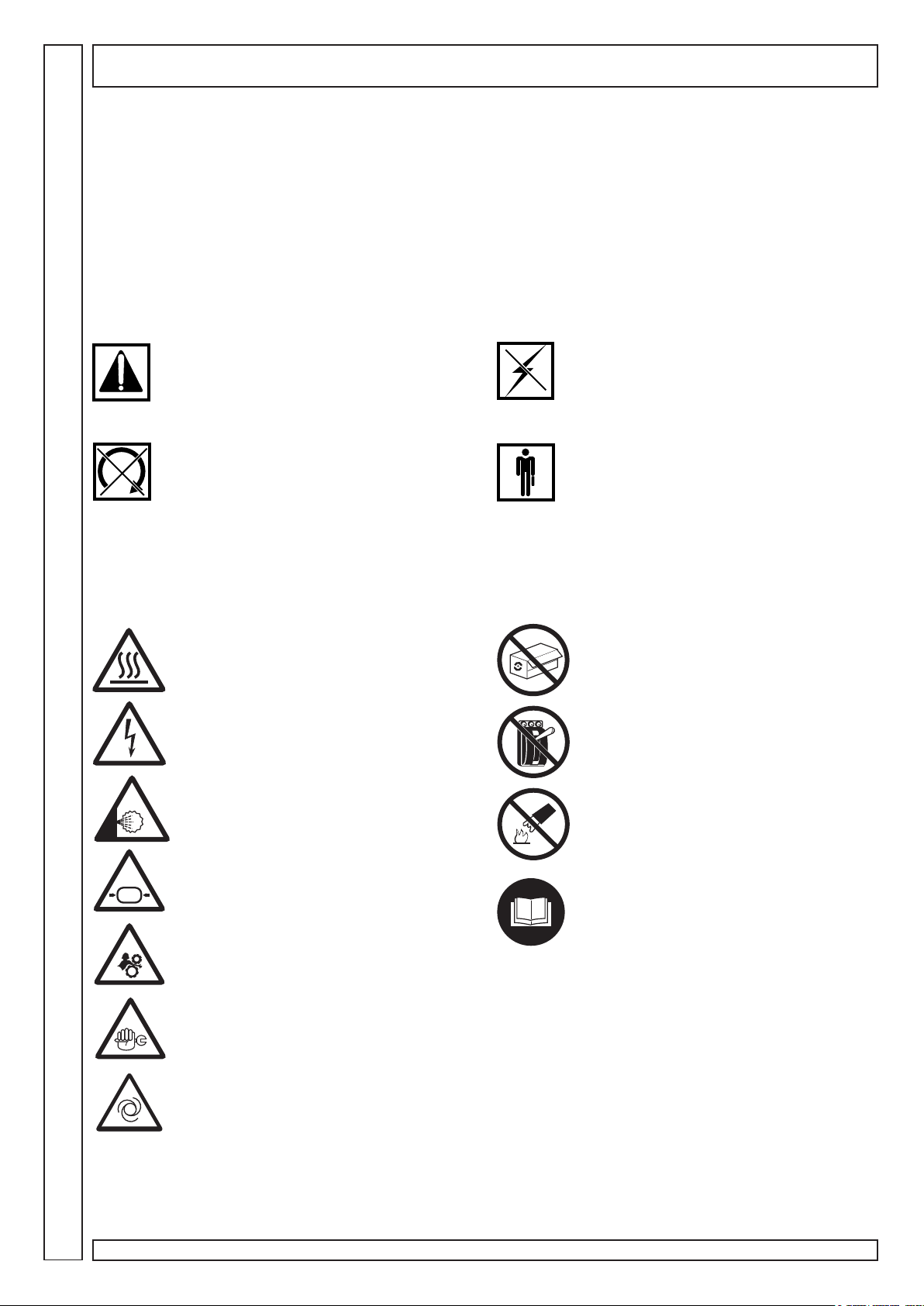
CAUTION!
Important description on service, dangerous
situation, safety, accident prevention
recommendations and/or very important
information.
STOP MACHINE!
All operations to be strictly carried out only after
stopping the machine.
POWER OFF!
All operations to be strictly carried out only after
powering off the machine.
SPECIALIZED PERSONNEL!
All operations to be strictly carried out only by
specialized technician.
SYMBOLS ON THE COMPRESSOR
The compressor has several labels to highlight possible danger and give recommendations on what to do during machine
operation or in special situations.
Please comply with these indications.
Danger! Hot!
Danger! Electric shock!
Prohibited! Do not open doors during
compressor operation
Prohibited! Press emergency button for
compressor immediate stop. Do not use line
knife switch.
Danger! Hot gas or harmful gas within
working area
Danger! Pressurized container
Danger! Mechanical moving parts
Caution! Maintenance works in progress
Prohibited! Do not use water on electric
equipment to extinguish fire.
Compulsory! Read instructions for use
carefully.
Read this page carefully before performing any operation on the compressor
Machine with automatic start-up
44
4
44
Rotar Cube SD 5-7-10 - Cod.197CC5200 Ed.1 - 07/2009
Page 5
SAFETY INDICATIONS
WHAT TO DO:
Make sure that mains voltage corresponds to the voltage indicated on CE plate and that cable of suitable cross-section are
used for electric connections.
Always check oil level before starting the compressor.
Be familiar with emergency stop control and all other controls.
Unplug the connector before any maintenance work, so to avoid accidental start.
Ensure that all parts have been correctly reassembled after any maintenance work.
Keep children and animals off the working area to avoid injuries caused by devices connected to the compressor.
Ensure that temperature of the working environment ranges between +5 and + 50 ºC.
The compressor should be installed and operated in a non-explosive environment.
Allow at least 80 cm between the compressor and the wall so to allow free air flow to the fan.
Press the emergency button on the control panel only in case of actual need so as to avoid possible damages to people or
the very compressor.
When calling for technical assistance and/or advice, always mention model and serial number indicated on CE plate.
Always follow the maintenance schedule specified in the user’s guide.
WHAT NOT TO DO:
Do not touch inner parts and pipes as they are very hot during compressor operation and stay hot for a certain time after
compressor stops.
Do not position inflammable or nylon objects or cloths close to and onto the compressor.
Do not move the compressor when the tank is under pressure.
Do not operate the compressor if the power cable is damaged or defective or if connection is unstable.
Do not operate the compressor in wet or dusty environments.
Never aim the air jet at people or animals.
Do not allow unauthorized people to operate the compressor and give them all required instructions.
Do not hit fans with blunt objects as they might break during compressor operation.
Never operate the compressor without air filter.
Do not tamper with safety and adjusting devices.
Never operate the compressor when doors/panels are open or removed.
GB
PRODUCT IDENTIFICATION
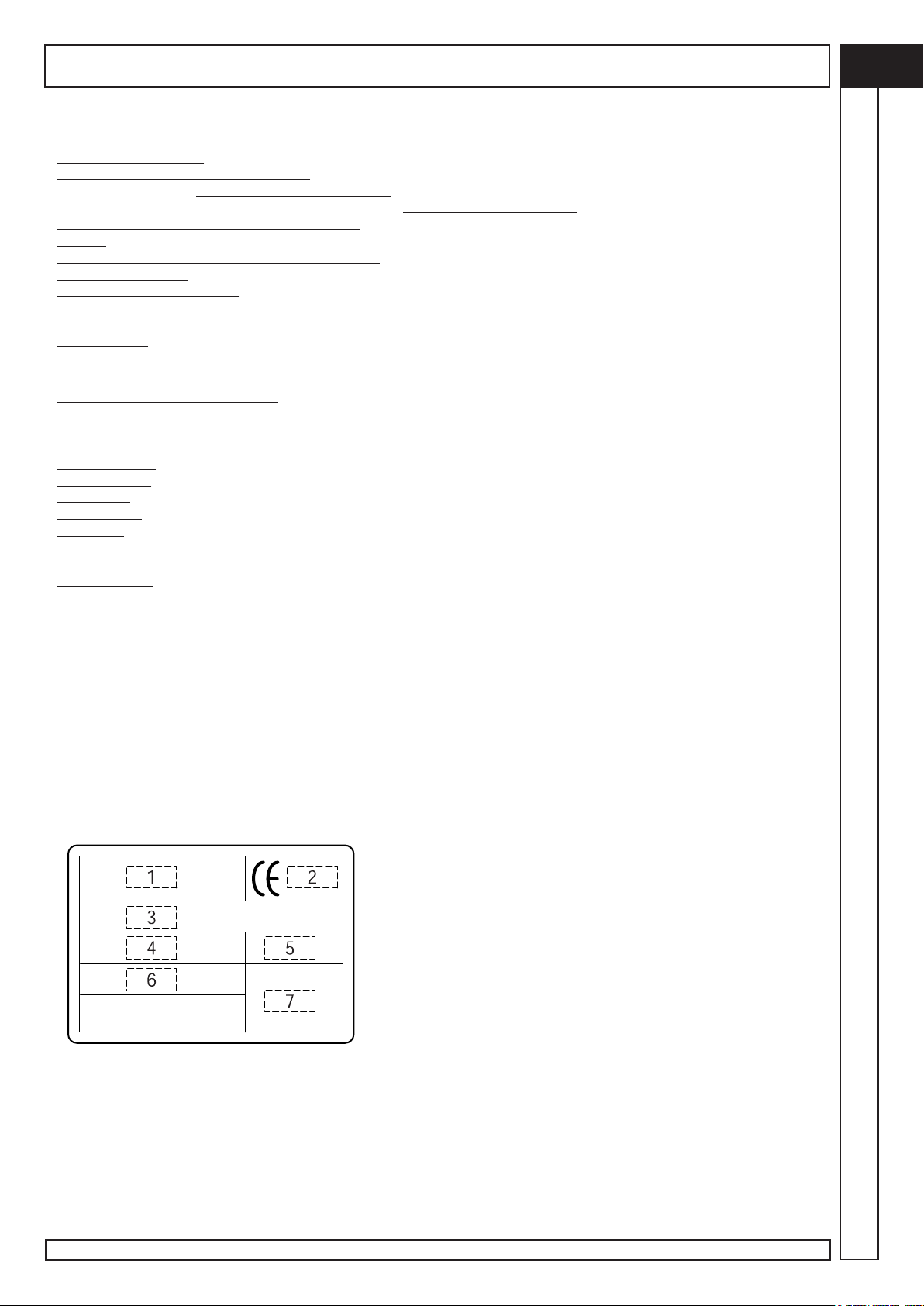
The compressor Your have purchased has its own CE plate showing the following data:
1) Manufacturer’s data
2) CE mark – year of manufacture
3) TYPE = name of the compressor
CODE = compressor code
SERIAL NO. = serial number of the compressor You have purchased (to be always mentioned when calling for technical
assistance)
4) air delivered by the compressor expressed in (l/min) and (cfm)
5) max. operating pressure (bar and PSI) – compressor noise level in dB(A)
6) electric data: voltage (V/ph), frequency (Hz), absorption (A) - power (HP and kW), rotations per minute (Rpm).
7) other approvals
Read this page carefully before performing any operation on the compressor
Rotar Cube SD 5-7-10 - Cod.197CC5200 Ed.1 - 07/2009
55
5
55
Page 6
GB
7A
INSTALLATION
1
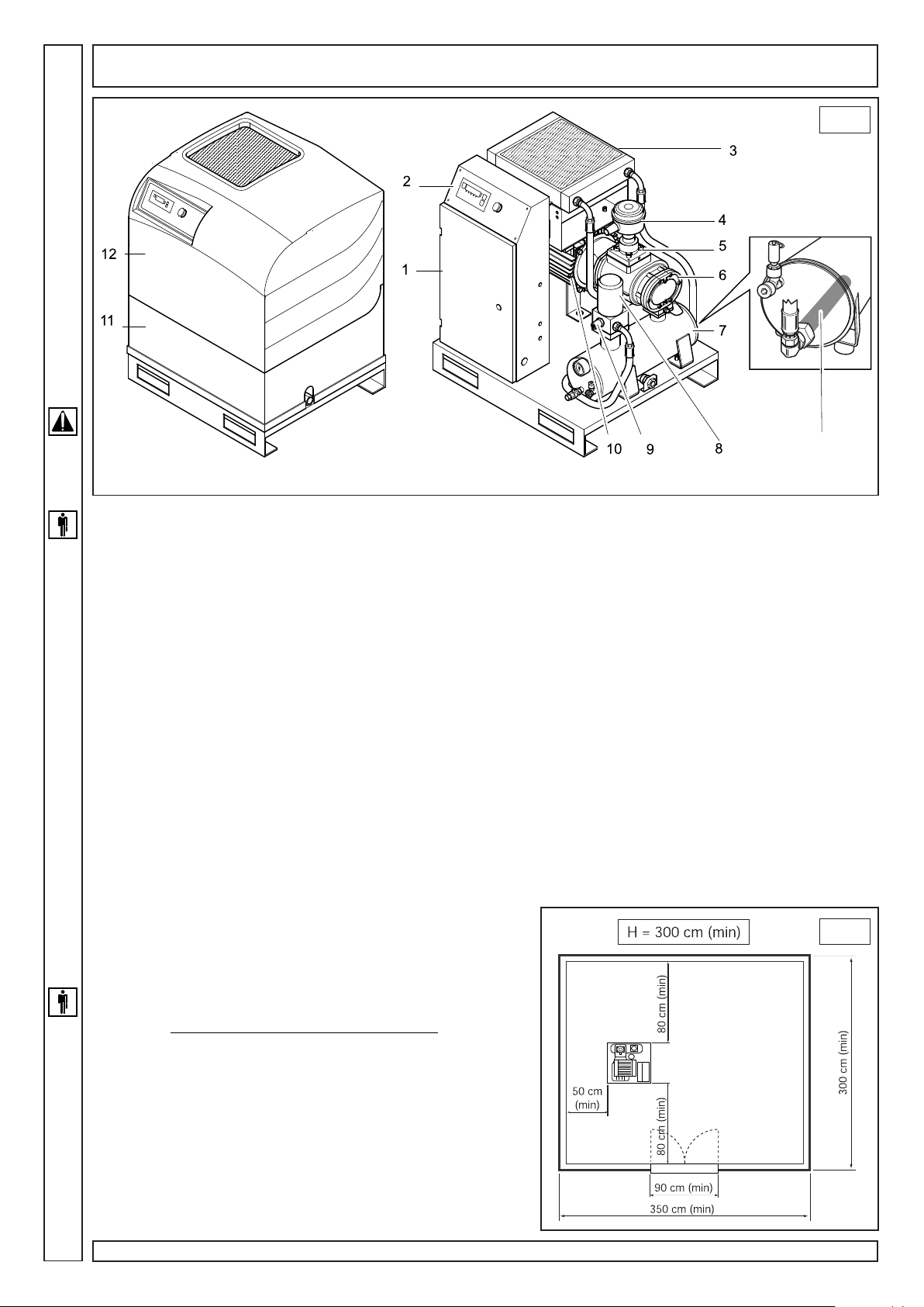
MACHINE DESCRIPTION (fig.1)
The compressor essentially consists of the following:
1. Electrical equipment
2. Control panel
3. Oil radiator
4. Air filter
5. Suction regulator
6. Screw compressor
7. Oil separator tank
7A. Oil filter
8. Oil separator filter
9. Minimum pressure valve
10. Electric motor
11. Lower fairing
12. Upper fairing
UNPACKING AND HANDLING THE MACHINE
When delivered, compressor top is protected by cardboard packing.
Wear suitable protective gloves and then cut outer straps and then remove cardboard from the top. Check the (outer) good
condition of the machine before moving the compressor. Visually check that no parts are damaged. Also ensure that all
accessories are available.
Lift the machine using a fork lift truck. Fit the anti-vibration elements into their proper seat and move the machine to the room
chosen for its location with maximum care.
Keep all packing materials at least for the warranty period for possible moving. In case of need, it will be safer for delivery
to the technical assistance dept.
Then, dispose of packing materials in compliance with current laws.
LOCATION (fig. 2)
The room chosen for the installation of the compressor should meet
the following requirements and comply with what is specified in the
current safety and accident prevention regulations:
•low percentage of fine dust,
• proper room ventilation and size that allow room temperature
under 50°C. In the event of inadequate hot air discharge, fit the exhaust
fans as high as possible.
Exhaust flow rate “2000 m3 /hr” part no. 020041000
Exhaust flow rate “4000 m3/hr” part no. 020042000
Condensate should be collected either into a pit or a tank.
The dimensions of the spaces are indicative only but it is advisable
to follow them as closely as possible.
2
66
6
66
Rotar Cube SD 5-7-10 - Cod.197CC5200 Ed.1 - 07/2009
Page 7
INSTALLATION
GB
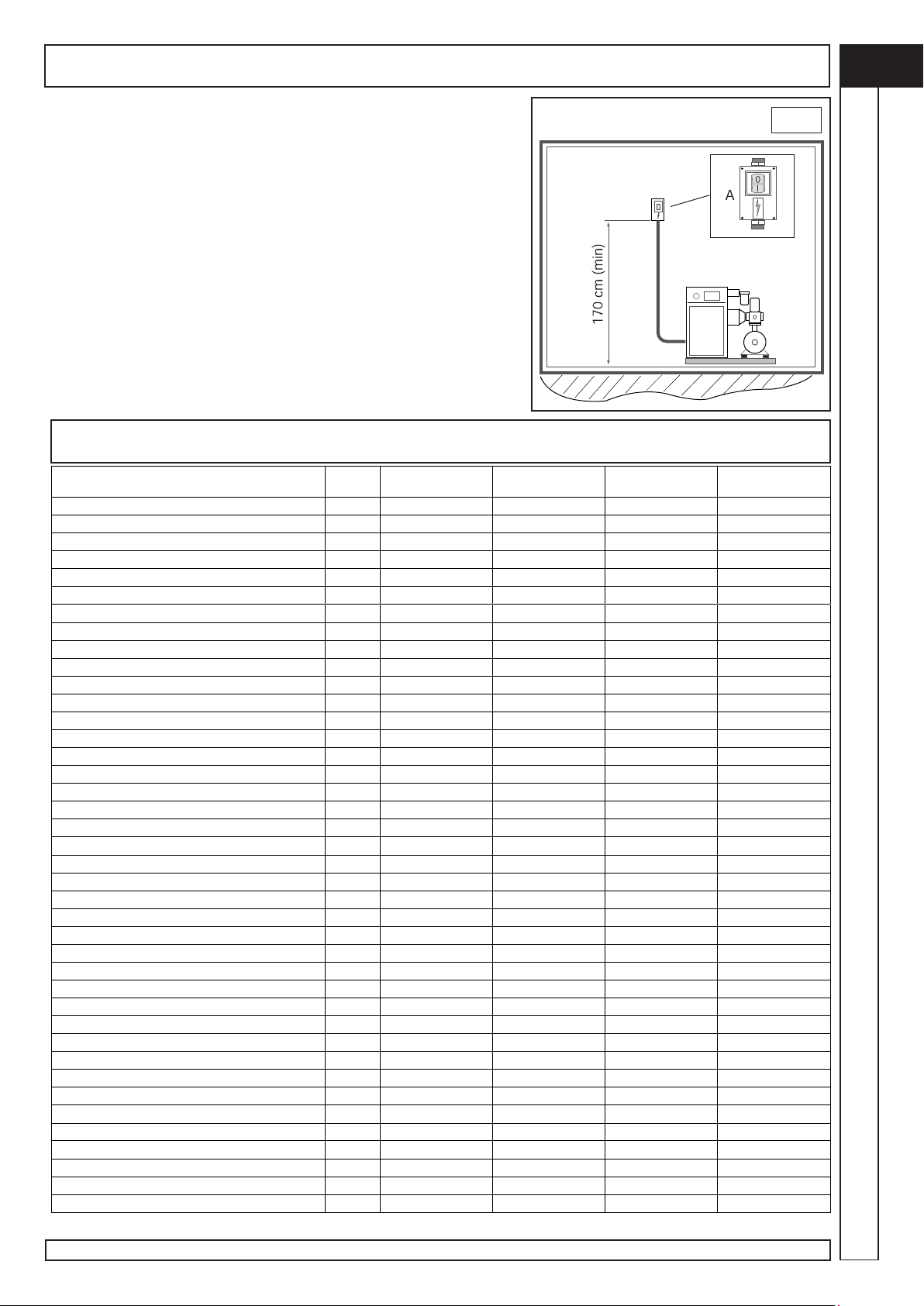
ELECTRICAL HOOK-UP (fig. 3)
• The mains cable should have a cross-section suitable for the
machine power and should include no. 3 phase wires, no. 1 neutral cable
and no. 1 earth wire.
• Between the mains cable and the compressor control panel a fused
switch near the point where the cables go into the machine is absolutely
necessary. The switch should be at least at 1.7 m from the ground.
• The switch (A) should be easily reached by the operator. The cables
should be of the approved type and installed with the following grade of
protection: minimum IP44
N.B. Follow the instructions in the table to select proper cable section.
TECHNICAL FEATURES
Technical features
Pressure
Compressor type
Com pressor rotation speed
Air volume supplied
Oil quantity
Oil quantity for topping-up
Max. final over temperature
Removed heat
Fan flow rate
Oil residues in the air
Electric motor
Motor power
Max. power absorbed
Electrical box protection class
Max. Start-up per hour
Ambient limit temperature
Noise leve l
Electrical data
Voltage
Auxiliary voltage
Start-up Absorbed current
Max. Absorbed current
Max. Absorbed current (vacuum)
Electrical motor protection class
Motor ins u lation class
Service factor
Protection devices
Max oil temperature
Pre-alarm Oil temperature
Motor thermal relay setting
Safety valve setting
Dimensions and weight
Length
Width
Height
Weight
Air fitting
bar 10 10 10 10
type FS26TFC FS26TFC FS26TFM FS26TFC
rpm 1400 1400 2900 2900
l/min 460 460 705 1050
l 3,5 3,5 3,5 3,5
l 0,5 0,5 0,5 0,5
°C 20 20 20 20
kJ/h 13680 13680 18800 25600
m3/h 670 670 670 1060
mg/m3
type 112 MC/4 112 MC/4 112 MC/2 112 MC/2
kW 4 4 5.5 7,5
kW 4,7 4,7 7,1 8,6
IP 54 54 54 54
n° 10 10 10 10
°C +2/+45 +2/+45 +2/+45 +2/+45
dB(A) 63 63 68 67
V/Hz 400/50-60 400/50-60 400/50-60 400/50-60
V/Hz 24/50-60 24/50-60 24/50-60 24/50-60
Amp 52 24 30 34
Amp 9,8 9,8 11,8 14,6
kW 1,82 1,82 2,74 3,16
IP 55 55 55 55
F F F H
1,1 1,1 1,1 1,1
°C 110 110 110 110
°C 105 105 105 105
Amp 10,5 6,4 6,8 10,5
bar 14 14 14 14
mm 570 570 570 570
mm 630 630 630 630
mm 800 800 800 800
kg 96 96 96 96
Rp ½" ½" ½" ½"
Cube SD5
(Direct start) Cube SD5 Cube SD7 Cube SD10
4 4 4 4
Rotar Cube SD 5-7-10 - Cod.197CC5200 Ed.1 - 07/2009
3
77
7
77
Page 8
GB
CONTROLS AND SETTINGS
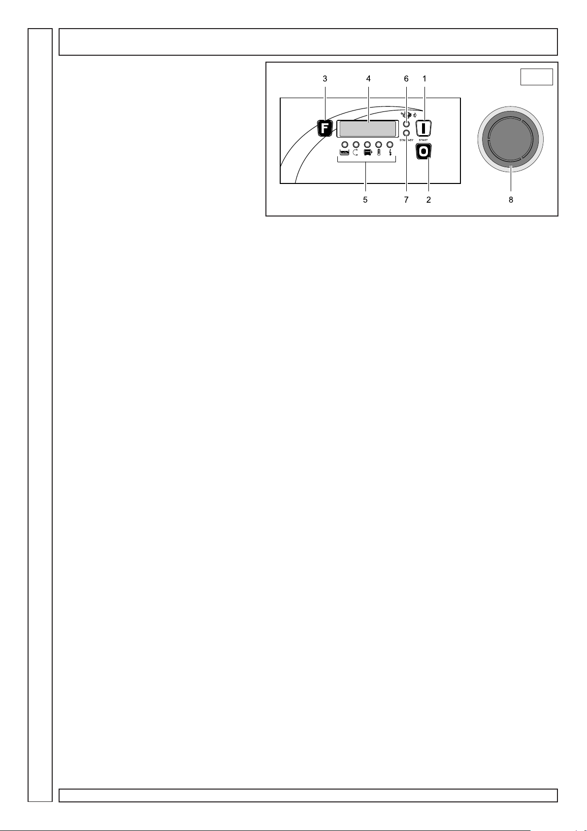
CONTROL PANEL
• All compressor power-on-and-off
procedures are controlled by the machine power
unit. Furthermore, it signals possible machine
problems and gives information on the operation
times and the maintenance operation times
4
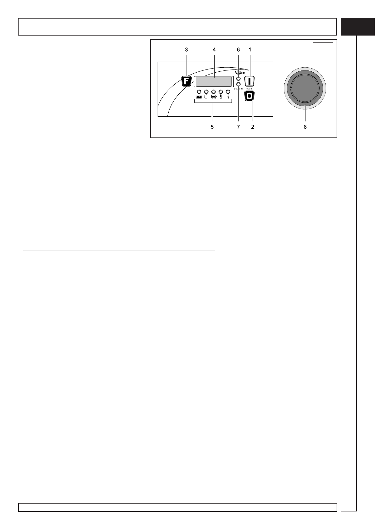
Figure 4:
1. START key:
controls start up of the compressor.
2. RESET key:
controls turning off of the compressor.
3. “Function” key:
allows movement from one display to the other.
4. Display:
shows the information.
5. Alarm warning lights:
turn on in case of alarm.
6. Screw warning light:
turning on means that the compressor is loading.
7. Stand-by warning light:
turning on indicates the compressor is waiting.
8. Emergency shutdown button:
pressing this button causes immediate stoppage of the compressor. To be used only and exclusively in the event of real
need.
RESET
WORKING TIMES
Automatic mode
• The compressor operation is controlled by the pressure switch, which stops the machine when the max. pressure
value is reached and starts it again after the pressure has decreased to the min. set value.
• Stoppage of the compressor is delayed; by pressing RESET (2) the compressor begins to operate loadless and stops
after 60 seconds. The Standard setting is 60 seconds, but it is recommended to check that number of start-ups per hour does
NOT exceed max number of 10. Should it be a higher value, it is recommended to set longer loadless operation time and
avoid useless turning on and off cycles.
PRESSURE REGULATOR
The User should install a pressure regulator downstream of the compressor to set the power line according to his/her
needs.
88
8
88
Rotar Cube SD 5-7-10 - Cod.197CC5200 Ed.1 - 07/2009
Page 9
CONTROLS AND SETTINGS
MODIFIABLE PARAMETERS
These settings apply exclusively to the models fitted with Easytronic II Micro power unit.
User menu
With the compressor off, keep the “Function” key pressed for at least 5 seconds.
N° Parameter U.M Min. value Default value Max value
U0 Set loadless pressure (*) Bar 0.5 10.0 15.0
U1 Set loading pressure (**) Bar 0 8.5 (Set P loadless) – 0.5
U2 Unit of measure (***) Bar/Psi 0 1 1
• to select the parameter desired use START (forward) and RESET (back) keys,
• then press the FUNCTION key to show the value of the chosen parameter,
• to change the value use START (to increase) and RESET keys (to decrease),
• confirm the value set by pressing the FUNCTION key.
• The power unit returns to the main menu, and after 5 seconds without pressing any key it returns to the standard
display.
(*) Set loadless pressure: indicates the value of pressure at which the compressor starts the loadless operating cycle.
(**) Set loading pressure: indicates the value of pressure at which the compressor starts compressing air again.
(***) 1=bar, 0=psi
Assistance menu
The settings below must be performed only by authorised technicians.
GB
With the compressor off or in alarm status, keep the “FUNCTION” and “RESET” buttons pressed for at least 5 seconds, then
a password will be requested.
N° Parameter U.M Min. value Default value Max value
A0 Temperature to power fan °C 0 80 150
A1 Time loadless sec. 30 75 900
A2 Delay time in stoppage phase sec 30 60 900
A3 Enable pressure sensor (*) 0 1 1
A4 Enable temperature sensor (*) 0 1 1
A5 Enable automatic start (*) 0 0 1
A6 Enable phase sequence (*) 0 1 1
A7 Expiry oil hours hours 0 2000 65536
A8 Expiry oil filter hours hours 0 2000 65536
A9 Expiry air filter hours hours 0 2000 65536
A10 Expiry oil separator hours hours 0 4000 65536
A11 Total hours (**) hours 0 — 65536
A12 Loading hours (**) hours 0 — 65536
A13 Reset parameters (***) 0 0 2
(*) 1=enabled, 0=disabled
(**) it is the real value of use of the compressor
(***) adapts the default parameters to the models of compressors on which the power unit is installed
• to select the parameter desired use START(forward) and RESET keys (back),
• then press the FUNCTION key to show the value of the chosen parameter,
• to change the value use START (to increase) and RESET keys ( to decrease),
• confirm the value set by pressing the FUNCTION key.
• The power unit returns to the main menu, and after 5 seconds without pressing any key it returns to the standard
display.
Rotar Cube SD 5-7-10 - Cod.197CC5200 Ed.1 - 07/2009
99
9
99
Page 10
GB
ALARMS
During normal operation of the compressor the following signals can occur:
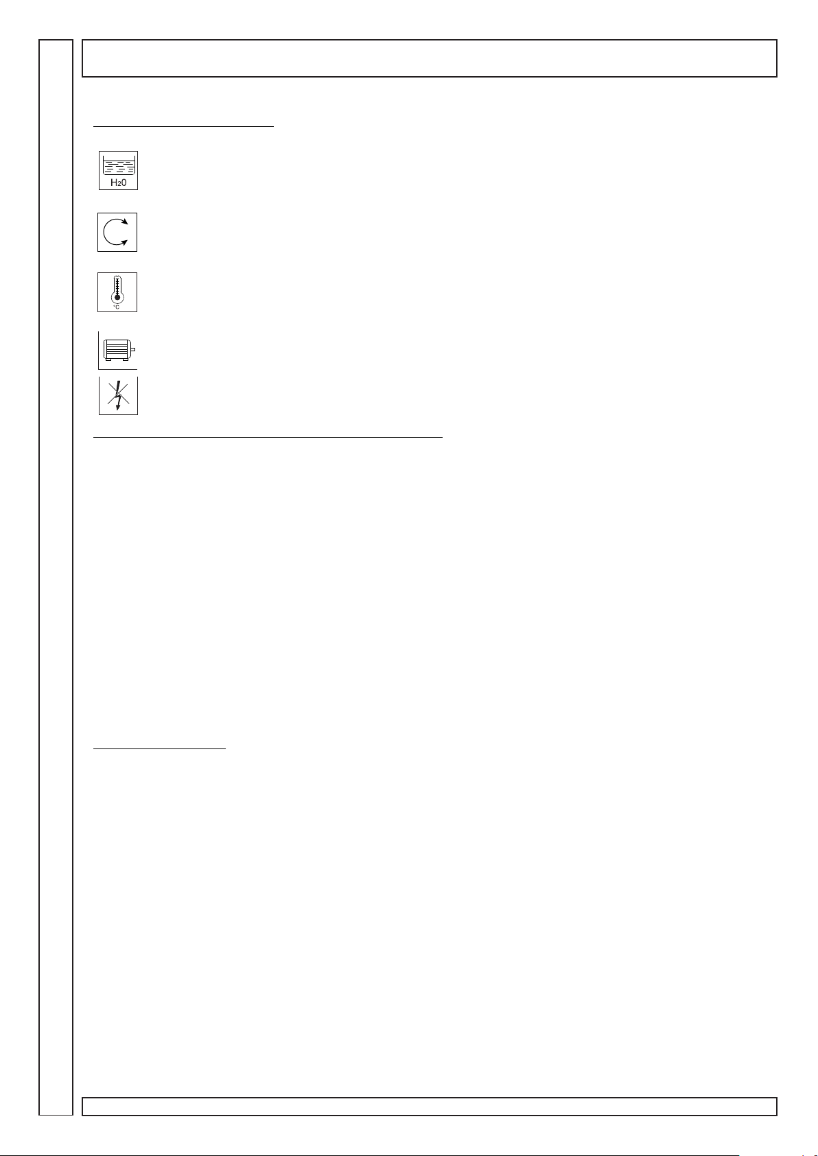
Alarm warning lights (rif.5, fig.5)
Water in the oil separator tank.
Blinking warning light = signal without compressor block
Fixed warning light = compressor block
Drain the condensate from the oil separator tanks (see chapter “Maintenance”).
The warning light turns on to indicate a wrong electrical connection. The compressor blocks.
Check connection to the mains cable and to the terminals of the electrical panel of the compressor.
Oil temperature.
Blinking warning light = pre-alarm without compressor block
Fixed warning light = alarm with compressor block
Let the compressor cool down and check the oil level.
The maximum temperature of the motor has been exceeded. The compressor blocks.
Let the motor cool down and check setting of thermal relay.
Indicates there has been a blackout. The compressor blocks.
With compressor stopped, press RESET to disable the alarm before restarting.
Alarm messages, the following alarms are shown on screen:
AL1 Faulty or broken temperature sensor with blockage of compressor.
Replace sensor.
AL2 Faulty or broken pressure sensor with blockage of compressor.
Replace sensor.
AL3 No phase or phase sequence transformer not operational with blockage of compressor.
Check presence of phase and if necessary replace transformer.
AL4 Maximum alarm pressure with blockage of compressor.
Contact an assistance centre to remove the cause of the problem.
AL5 Fast rise in temperature with blockage of compressor.
Contact an assistance centre to remove the cause of the problem.
AL6 The emergency button has been pressed.
Reset the button to correct position.
All alarms cause the compressor to block, which can be restarted only when the problem which has caused the blockage
is resolved.
The alarm signal remains even after the problem has been solved, to disable it press the RESET button before restarting
the compressor.
Maintenance signalling
The power unit also signals periodic maintenance operations, the internal counters decrease at each hour of loading of the
compressor until zero is reached, at this point the maintenance signal will appear on the display:
CH1 Expiry of oil hours.
Replace oil.
CH2 Expiry of oil filter hours.
Replace oil filter
CH3 Expiry air filter hours
Replace air filter.
CH4 Expiry of oil separator hours
Replace oil separator filter.
1010
10
1010
If more signals are verified at the same time they are displayed in sequence.
Once the maintenance has been performed the internal counters must be reprogrammed.
Rotar Cube SD 5-7-10 - Cod.197CC5200 Ed.1 - 07/2009
Page 11
START-UP
GB
Before starting the machine for the first time,
check that:
• the mains voltage is the same as the
voltage on the CE plate;
• the electric connections have been made
using cables of proper cross-section,
• the (wall) main power switch has suitable
fuses;
• the oil level is over the minimum level -
top up with the same type of oil if necessary;
CONNECT THE TANK WITH A HOSE.
Only specialised technicians can start the compressor for the first time.
The turning on procedure starts by pressing the START key (1).
The stand-by led (7) blinks and after a few seconds the presence of the phases and their correct sequence is checked,
if the compressor blocks and the warning light turns on the phase sequence device has intervened, press the RESET key
(2) and bring the wall switch to OFF position. Open the electric compartment and invert the position of two phases in the
power terminal box. Close the electrical compartment and restart.
The start up procedure is repeated: the Screw led (6) blinks and after a few seconds it becomes fixed, the load phase
starts until the “set loadless pressure” value is reached.
The Screw led (6) blinks again and the loadless operation phase begins.
If at the end of the loadless operation (default 75 sec.) the pressure has not fallen below the “set load pressure” value the
compressor stops and the stand-by led turns on (7); otherwise upon reaching the “set load pressure” value the compressor
restarts the loading phase and the Screw led turns on in fixed mode (6).
RESET
4
During routine operation the following information is displayed on screen:
pressure,
temperature,
total hours of operation (with compressor on),
hours of operation loaded (with compressor in load phase).
By pressing the RESET key (2) the turn off procedure starts, the Screw led (6) blinks and the compressor enters the
loadless operation mode for the time set by the parameter “delayed stop time” (default 60 sec.). At the end of the cycle the
compressor stops.
Rotar Cube SD 5-7-10 - Cod.197CC5200 Ed.1 - 07/2009
1111
11
1111
Page 12
GB
OPERATION
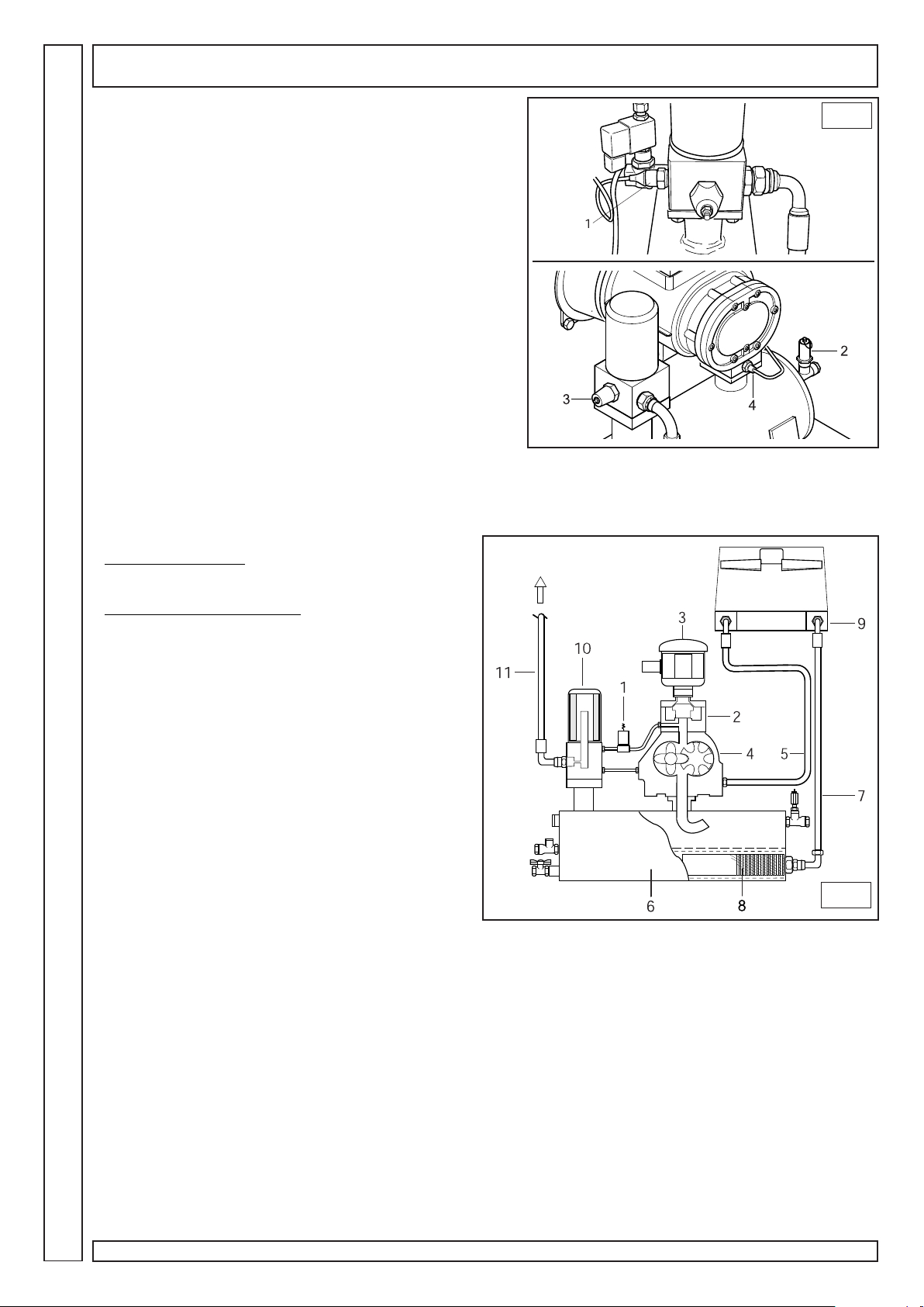
SAFETY AND CONTROL DEVICES (fig.5)
1) Pressure switch :
regulates STOP and START pressure
2) Safety valve:
opens the air drainage to the safety valve.
3) Minimum pressure valve:
prevents leakage of compressed air if the pressure is below the
calibration value of the valve
4) Maximum temperature probe:
shuts down motor when 110° is exceeded
OPERATING CYCLE
Cube 5 Direct starting
1) in the first start up the motor starts directly; it reaches
standard speed after 5-7 seconds.
Cube 5- 7-10 Remote starting
1) At first start up the motor starts in the “star”
configuration. In this phase the compressor starts slowly,
the solenoid (1) is open, and the suction regulator (2) is
closed.
The compressor remains in this condition for about 5÷7
seconds, after this time the motor is powered by the “delta”
configured circuit.
5
2) The solenoid valve (1) receives current and closes
allowing the opening of the suction regulator (2), which
intakes atmospheric air through the filter (3).
3) At this stage, the compressor runs at full speed and
begins to compress the air in the tank (6).
4) The compressed air cannot come out from the
minimum pressure valve set at 3÷4 bar.
5) The compressed air compresses the oil in the tank
(6) and forces it to flow through the filter (8) and pipe (7) to
the radiator (9).
6) If the oil temperature is below 80 °C the solenoid valve
stays still.
7) If the oil temperature exceeds 80°C the solenoid valve starts operating and cooled oil returns to the compressor
through tubes (5).
8) The oil reaches the compressor (4) mixing with the intake air creating an air/oil mixture which ensures the seal and the
lubrication of the moving parts of the compressor.
9) The air/oil mixture returns to the tank (6) where the air is pre-separated and later a final separation of the oil takes
place, through the oil separator filter (10), and finally it is conveyed to the distribution network.
6
1212
12
1212
Rotar Cube SD 5-7-10 - Cod.197CC5200 Ed.1 - 07/2009
Page 13
MAINTENANCE
• Correct maintenance is crucial to achieve maximum efficiency of your compressor, and to lengthen its operating life.
• It is also important to comply with the maintenance intervals recommended, but it must be remembered that such
intervals are suggested by the manufacturer in the event that the environmental conditions of use of the compressor are
optimal (see “Installation” chapter).
• The maintenance intervals can therefore be reduced depending on the environmental conditions in which the
compressor operates.
• The oil used is RotEnergy Plus, the use of a different oil does not guarantee perfect efficiency and compliance with the
maintenance intervals.
• The following pages describe the routine maintenance operations which can be performed by the person in charge of
the compressor, the non-routine maintenance operations must instead be performed by an authorised technical assistance
centre.
Maintenance table
MAINTENANCE OPERATION MAINTENANCE INTERVAL
working hours o at least
ROUTINE MAINTENANCE
Condensate drain - 1 time a month
Check oil and possible top up 500 -
Clean air filter 1000 -
Check blockage and clean radiator 1000 - -
Replace air filter 2000 1 time a year
Replace oil filter 2000 1 time a year
Replace oil separator filter 4000 1 time a year
Replace oil 2000 1 time a year
NON-ROUTINE MAINTENANCE
Replace one-way drain valve 4000 1 time a year
Review suction valve 12000 -
Review thermostat valve 12000 -
Review minimum pressure valve 12000 -
Replace solenoid valve 12000 -
Replace bearings electric motor 12000 -
Replace hoses 12000 - -
Review screw 24000 -
GB
If the hourly limit is not reached, the maintenance operations highlighted in bold must be performed at least 1 time a year.
• To verify correct machine operation, perform the followng checks after the first 100 hours of work:
1) Check the oil level: top up with the same type of oil if necessary.
2) Check for proper screw tightening: in particular the power electric connection screws.
3) Visually check that all fittings seal properly.
4) Check room temperature.
BEFORE MAINTAINING THE MACHINE ALWAYS PERFORM THE FOLLOWING:
¹ Press the machine automatic stop button (do not use the emergency button).
¹ Power the machine off by means of the wall outer switch.
¹ Close the line cock.
¹ Make sure that no compressed air is inside the oil separator tank.
¹ Remove fairing and/ or panels.
Rotar Cube SD 5-7-10 - Cod.197CC5200 Ed.1 - 07/2009
1313
13
1313
Page 14
GB
MAINTENANCE
7
H
B
G
F
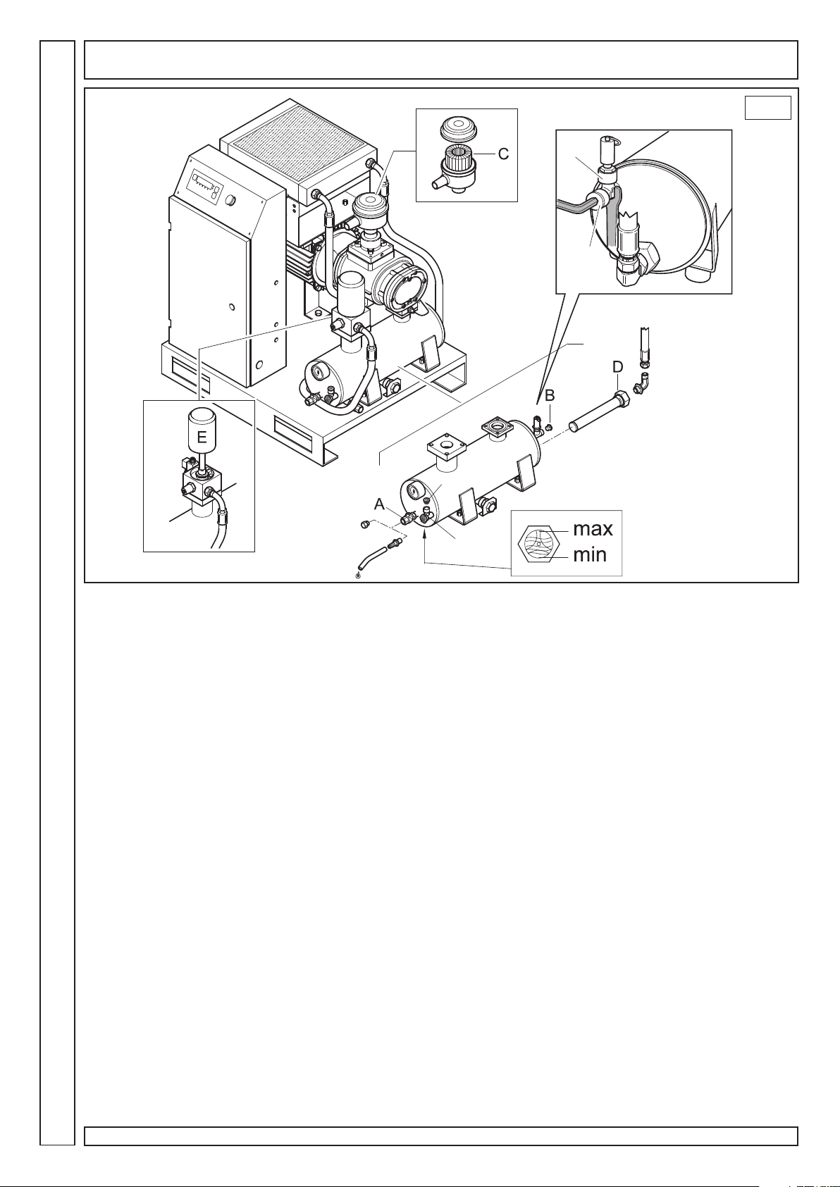
DRAIN CONDENSATE
The oil/air mixture cooling is set at a higher temperature with respect to the dew point of the air (under standard operating
conditions of the compressor). However, the condensate in the oil cannot be fully removed.
Blow off compressed air through cock A and then close it as soon as oil begins to flow out instead of water. Check the oil
level and top up if necessary
CONDENSATE IS A POLLUTING MIXTURE! It must not be let into the sewage.
OIL CHECK AND TOP UP IF NECESSARY
Check oil level through the warning light on the left side of the oil separator tank, if the level is below the maximum, top up
through union F; before topping up keep fitting H in a vertical position with a key and unscrew plug B to allow the air to exit
during the top up.
The quantity of oil required to top up from the minimum to the maximum level is about 0.5 litres.
CLEAN / REPLACE AIR FILTER
Clean the air filter C from the inside towards the outside using compressed air.
Check against the light for possible cuts: replace the filter if any.
The filter cartridge and the cover should be assembled with care, so that no dust goes into the compression unit.
CLEAN RADIATOR
Clean the radiator in case of excessive over temperature and at least once a year.
Proceed as follows:
• Remove the radiator unit and spray (with spray gun + solvent) from the outside towards the inside;
• check for proper air flow through the radiator.
CHANGE OIL
When the compressor temperature is over 70°C change the oil.
• Insert the hose supplied onto cock A.
• Keep the fitting H in a vertical position with a spanner and unscrew the plug B to allow the air to flow out
• Open cock A and allow oil to flow into a collection tray, until complete drainage. Close the cock and remove the hose.
• Remove plug G and pour new oil from union F (quantity to fill up completely: 3.5 litres).
• Close plug B and plug G.
• Power the machine on.
1414
14
1414
Rotar Cube SD 5-7-10 - Cod.197CC5200 Ed.1 - 07/2009
Page 15

MAINTENANCE
• Start the machine and wait 5 minutes, then stop the machine.
• Blow the air off.
• Wait 5 minutes and check the oil level; top up if necessary.
The oil used is: RotEnergy Plus
THE EXHAUSTED OIL IS HIGHLY POLLUTANT! For its disposal comply with the current laws on environmental protection.
CHANGE OIL FILTER
Change oil filter D: this must occur when the tank is not under pressure and without oil.
Always apply some oil on the O ring seal of the filter, before refitting it manually.
CHANGE OIL SEPARATOR FILTER
The oil separator filter E cannot be cleaned, but must be replaced.
• Unscrew filter manually (or if necessary use an appropriate filter tool) turning it anticlockwise.
• After having slightly greased the oil separator filter seal and O-ring, fit the new filter by turning clockwise.
GB
Rotar Cube SD 5-7-10 - Cod.197CC5200 Ed.1 - 07/2009
1515
15
1515
Page 16
GB
TROUBLESHOOTING
Problem
Motor stopped (thermal relay
operation signal)
Oil consumption high
Intake filter leaks oil
Safety valve opening
Sensor for compressor
temperature triggered
Cause
Voltage too low
Overtemperature
Fan motor overtemperature
Drainage faulty
Oil level too high
Oil separator filter broken
Oil separator filter seal leaking
Intake regulator stays open
Pressure too high
Intake regulator does not close
at the end of the cycle
Oil separator filter clogged
Room temperature too high
Radiator clogged
Remedy
Check voltage, press Reset and then restart.
Check motor absorption and relay setting. In case of
regular absorption press Reset and restart.
Check fan motor and clixon condition
Check oil drain hose and check valve
Check oil level and drain some, if necessary
Replace oil separator filter
Replace oil separator nipple seals
Check regulator and solenoid valve
Check service pressure switch setting
Check regulator and solenoid valve
Replace oil separator filter
Improve ventilation
Clean radiator with solvent
Compressor performance low
Compressor does not
compress air while running
Compressor compresses air
over max. pressure value
Compressor does not start
Compressor hardly starts
Oil level too low
Cooling fan does not start
Air filter dirty or clogged
Regulator closed. It cannot
open because dirty.
Regulator closed. It cannot
open because no command is
received.
Regulator open. It cannot open
because dirty.
Regulator open. It cannot open
because no command is
received.
Oil separator filter clogged
Min. pressure valve does not
close perfectly
Voltage too low
Top up oil
Check fan motor and clixon condition
Clean or replace filter
Remove intake filter and check for proper manual
opening. Remove and clean, if necessary.
Check for signal on solenoid valve. Replace
damaged part, if any.
Remove and clean regulator
Check for signal availability between pressure switch
and solenoid valve. Replace damaged part, if any.
Replace oil separator filter
Remove the valve, clean and replace seal, if
necessary
Check mains voltage
1616
16
1616
Tube leaking
Rotar Cube SD 5-7-10 - Cod.197CC5200 Ed.1 - 07/2009
Tighten fittings
Page 17
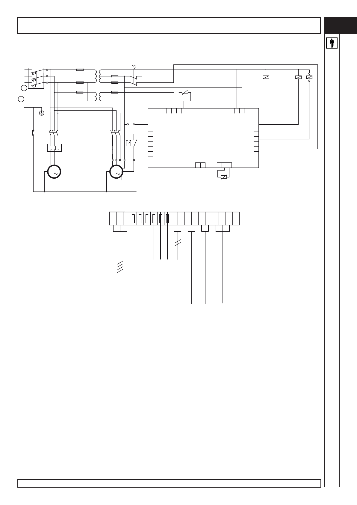
WIRING DIAGRAM - ROTAR CUBE 5 230-400V / 50-60Hz
GB
PE
10
3
YV
1
10
3
23
CN2
3
8
KM1
58
4
KM4
9
ST
CN4
321
-+
12
CN5
CN6
1
9
2
3
4
8
5
5
6
10
4
D
CN3
21
BP
(**)
13
4
4
14
V3U3 W3
4
1210
06
0
4
4
W3
PROT.TERMICA
MOTORE
E.VENTOLA
RADIATORE
SB
8
13
13
7
6
15
5
CN1
4
3
FR
2
2
14
1
14
R
S
TT
L1
L2
L3
A
FU1
FU2
FU5
= Inom x 1,5A
XB
KM1
TC1
L11
3
(0)
FU3
012
(12)
FU4
(24)
L31
24
FU6
TC2
L22
(6)
060
L31
(0)
KM4
FR
V1
U1
W1
MC
3
MOTORE
COMPRESSORE
U3
MV
3
MOTORE
E.VENTOLA
RADIATORE
V3
L1 L2 L3
(FU3)
(FU2)
(FU4)
(FU5)
(FU6)
(YV)
BRIDGE TO REMOTE
CHECK PRESSURE
THERMAL PROTECTION
MOTOR ELECTRIC FAN RADIATOR
MOTOR ELECTRIC FAN RADIATOR
(FU1)
LINE
230V 400V (*) = 400V AC3
TC1 Transformer 63VA Pr.0/230/400 Sec.0/12/24
TC2 Transformer Pr.0/230/400 Sec.0/6
SB Emergency button + 2NC 230V 10A
FU1/FU2/FU4
Ceramic fuses 6.3x32 GF 4A 500V
FU3 / FU5 Ceramic fuses 6.3x32 GF 1A 500V
FU6 Ceramic fuses 6.3x32 GF 500mA 500V
KM1 Contactor mot. compressor bobbin24V/50-60Hz 11 kW(*) 5.5 kW(*)
KM4 Contactor fan radiator bobbin24V/50-60Hz 3 kW(*) 3 kW(*)
FR Thermal relay / Reset man/aut - 1L+1R (14-20) (9-12)
YV Solenoid valve 24 VAC 50/60 Hz 8VA
BP Pressure switch 0.-16 bar 4-20 mA
D Easytronic electronic controller II 24V/AC
ST Thermal probe
MV Motor electric fan radiator 230/400V 50/60Hz 68/W 68/W
Sec. Cable motor (mm²) 4G4 4G1.5
Rotar Cube SD 5-7-10 - Cod.197CC5200 Ed.1 - 07/2009
1717
17
1717
Page 18
GB
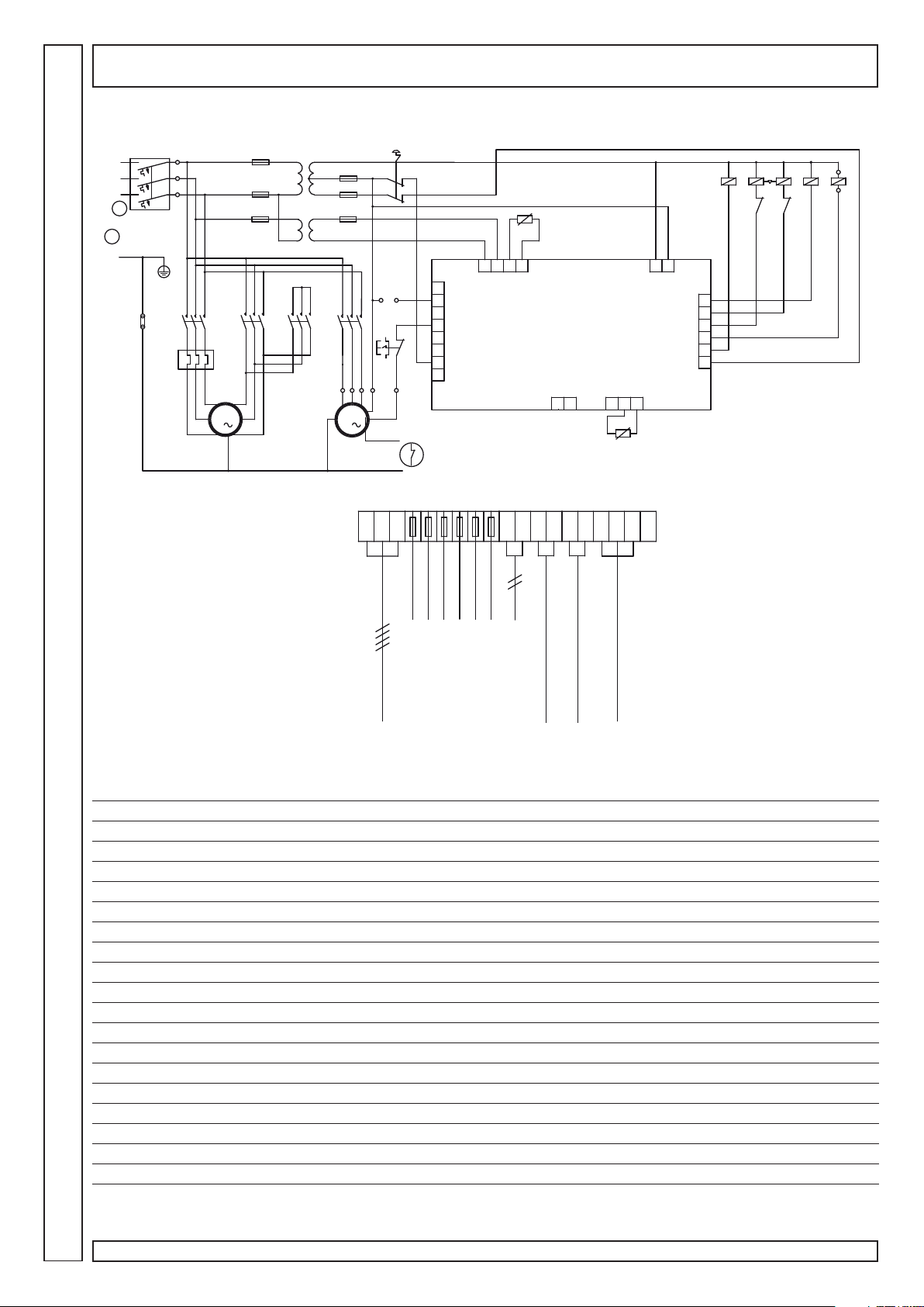
WIRING DIAGRAM - ROTAR CUBE 5-7-10 TA - 230-400V / 50-60Hz
PE
10
3
YV
1
10
3
23
CN2
3
ST1
4
8
13
D
CN3
21
4
KM4
KM3
KM2
567 8
9
KM3 KM2
CN4
321
-+
12
CN5
KM1
4
1
9
2
12
3
11
CN6
4
8
5
5
6
10
BP
(**)
4
V3U3 W3
14
4
1210
06
0
4
4
w3
PROT.TERMICA
MOTORE
E.VENTOLA
RADIATORE
SB
8
13
13
7
6
15
5
CN1
4
3
FR
2
2
14
1
14
ST2
Q
FU1
FU2
FU5
TC1
L11
3
(0)
FU3
012
(12)
FU4
(24)
L31
24
FU6
TC2
L22
(6)
060
L31
(0)
KM4
R
S
TT
L1
L2
L3
A
= Inom x 1,5A
XB
KM1 KM2 KM3
FR
v3
w1
v1
u1
MOTORE
COMPRESSORE
3
MC
w2
u2
v2
u3
MV
3
MOTORE
E.VENTOLA
RADIATORE
L1 L2 L3
(FU3)
(FU2)
(FU4)
(FU5)
(YV)
(FU6)
BRIDGE TO REMOTE
CHECK PRESSURE
THERMAL PROTECTION
MOTOR ELECTRIC FAN RADIATOR
MOTOR ELECTRIC FAN RADIATOR
(FU1)
LINE
Cube 5 Cube 7 Cube 10
230V 400V 230V 400V 230V 400V
TC1 Transformer Pr.0/230/400 Sec.0/12/
TC2 Transformer Pr.0/230/400 Sec.0/6
SB Emergency button + 2NC 230V 10A
FU1/ FU2/ FU4Ceramic fuses 6.3x32 GF 4A 500V
FU3 / FU5 Ceramic fuses 6.3x32 GF 1A 500V
FU6 Ceramic fuses 6.3x32 GF 500mA 500V
KM1 Contactor line bobbin 24V/50-60Hz 5.5kW(*) 4kW(*) 7.5kW(*) 4kW(*) 11kW(*) 5,5kW(*)
KM2 Contactor triangle bobbin 24V/50-60Hz 5.5kW(*) 4kW(*) 7.5kW(*) 4kW(*) 11kW(*) 5,5kW(*)
KM3 Contactor star bobbin 24V/50-60Hz 4kW(*) 4kW(*) 5.5kW(*) 4kW(*) 7.5kW(*) 4kW(*)
KM4 Contactor fan radiator bobbin 24V/50-60Hz 3kW(*) 3kW(*) 3kW(*) 3kW(*) 3kW(*) 3kW(*)
FR Thermal relay / Reset man/aut - 1L+1R (9-12) (5.5-8) (9-12.5) (7-10) (14-20) (3-12)
Y V Solenoid valve 24 VAC 50/60 Hz 8VA
BP Pressure switch 0.-16 bar 4-20 mA
D Easytronic electronic controller II 24V/AC
ST1 Thermal probe for controller
MV Motor electric fan radiator 230/400V 50/60Hz
Sec. cable motor (mm²) 7G1.5 7G1.5 7G2.5 7G1.5 7x4 7G2.5
(*) = 400V AC3
1818
18
1818
Rotar Cube SD 5-7-10 - Cod.197CC5200 Ed.1 - 07/2009
 Loading...