

Page 1
AIR OPERATED CLUTCH &
BRAKE BLEEDING KIT
MODEL NO: CHT637
Part No: 1801637
OPERATING & MAINTENANCE
INSTRUCTIONS
GC01/12
Page 2
INTRODUCTION
Thank you for purchasing this CLARKE Clutch & Brake Bleeding Kit.
Before attempting to operate the product, it is essential that you read this
manual thoroughly and carefully follow all instructions given. In doing so you
will ensure the safety of yourself and that of others around you, and you can
also look forward to the product giving you long and satisfactory service.
GUARANTEE
This CLARKE product is guaranteed against faulty manufacture for a period of
12 months from the date of purchase. Please keep your receipt as proof of
purchase.
This guarantee is invalid if the product is found to have been abused or
tampered with in any way, or not used for the purpose for which it was
intended.
Faulty goods should be returned to their place of purchase, no product can
be returned to us without prior permission.
This guarantee does not effect your statutory rights.
2
Parts & Service: 020 8988 7400/E-mail:[email protected] or [email protected]
Page 3
CONTENTS
Introduction ............................................................................................ 2
Guarantee .............................................................................................. 2
Parts & Service ....................................................................................... 2
Table of Contents ................................................................................... 3
Technical Specification......................................................................... 3
General Safety Precautions .................................................................. 4
Equipment Components ....................................................................... 6
Principle of Operation ........................................................................... 7
Operation ............................................................................................... 7
Troubleshooting.................................................................................... 11
Maintenance ........................................................................................ 11
Parts Lists and Diagrams ..................................................................... 12
TECHNICAL SPECIFICATION
erutaeF noitacificepS
yticapaCdiulFrotcartxEsertiL2
noitpmusnoCriAlacipyT )esoh"8/3htiw(isp001@mfc8
kroWisp071-07
Please note that the details and specifications contained herein, are correct at the
time of going to print. However, CLARKE International reserve the right to change
specifications at any time without prior notice.
Parts & Service: 020 8988 7400/E-mail:[email protected] or [email protected]
erusserPriAgni
ezistelnIriA"4/1
yticapaCelttoBllifeRertiL1
mm)HxWxL(snoisnemiD )riovreser(572x021x051,)rotcar
thgieW)tinugnillifer(gk5.0,)rotcartxe(gk6.1
txe(553x052x052
3
Page 4
GENERAL SAFETY PRECAUTIONS
Warning: As with all equipment, there are certain hazards involved
with its operation and use. Exercising caution will reduce the risk
of personal injury .
WORK AREA
1. Keep the work area clean and well lit. Floors should always be kept clear.
Cluttered or dark areas invite accidents.
2. Keep children and bystanders away while operating machines and using
tools. Distractions can cause loss of control.
PERSONAL SAFETY
1. ALWAYS stay alert, watch what you are doing and use common sense
when operating this product. Do not use the product while you are tired or
under the influence of medication, drugs or alcohol. A moment of
inattention can result in personal injury.
2. Do not over-reach. Keep your proper footing and balance at all times
when positioning the product.
3. Brake fluid is highly corrosive. It is advisable to always wear gloves and
approved safety glasses at all times and always prevent contact with
painted surfaces.
4. ALWAYS store this product out of reach of children and do not allow
persons unfamiliar with these instructions to operate it.
5. ALWAYS thoroughly familiarise yourself with this product & its operation,
and always read and understand the instructions and warnings in this
manual before using the equipment.
GENERAL EQUIPMENT USE AND CARE
1. ALWAYS maintain the product with care and keep it clean for best / safest
performance.
2. NEVER use this product if any part is damaged. Have it inspected and
repaired by your local Clarke dealer.
3. NEVER modify or tamper with this product in any way. Use it only for the
purpose for which it is designed.
4. NEVER use the unit to extract or store flammable liquids, toxic or corrosive
chemicals or hold any fluids at very high temperatures
5. ALWAYS consult and follow the vehicle manufacturers recommended
procedures when working on any hydraulic system.
4
Parts & Service: 020 8988 7400/E-mail:[email protected] or [email protected]
Page 5

6. ALWAYS drain, wash and clean the unit immediately after each use.
7. ALWAYS ensure the extractor is in a level position.
8. NEVER drop, throw or mishandle this unit.
9. NEVER attempt to pressurise this unit. It is designed for vacuum use only.
10. ALWAYS make sure that the bleeding kit is in perfect condition before use
with no cracks which would result in oil leaks.
11. If fluid is spilt, the area must be cleaned completely and sand or sawdust
scattered on the area to absorb the fluid and then cleaned up. You
should also alert people in the vicinity to the possible danger of slipping.
12. ALWAYS comply with all local authority regulations when disposing of any
type of used oil.
13. ALWAYS have the unit repaired by your local CLARKE dealer, using only
identical replacement parts. This will ensure the safety of the unit is
maintained. The use of non standard parts could be hazardous.
Your CLARKE Bleeding Kit has been designed to give long and trouble free
service. If, however, having followed the instructions in this booklet carefully,
you encounter problems, take the unit to your local CLARKE dealer.
5
Parts & Service: 020 8988 7400/E-mail:[email protected] or [email protected]
Page 6
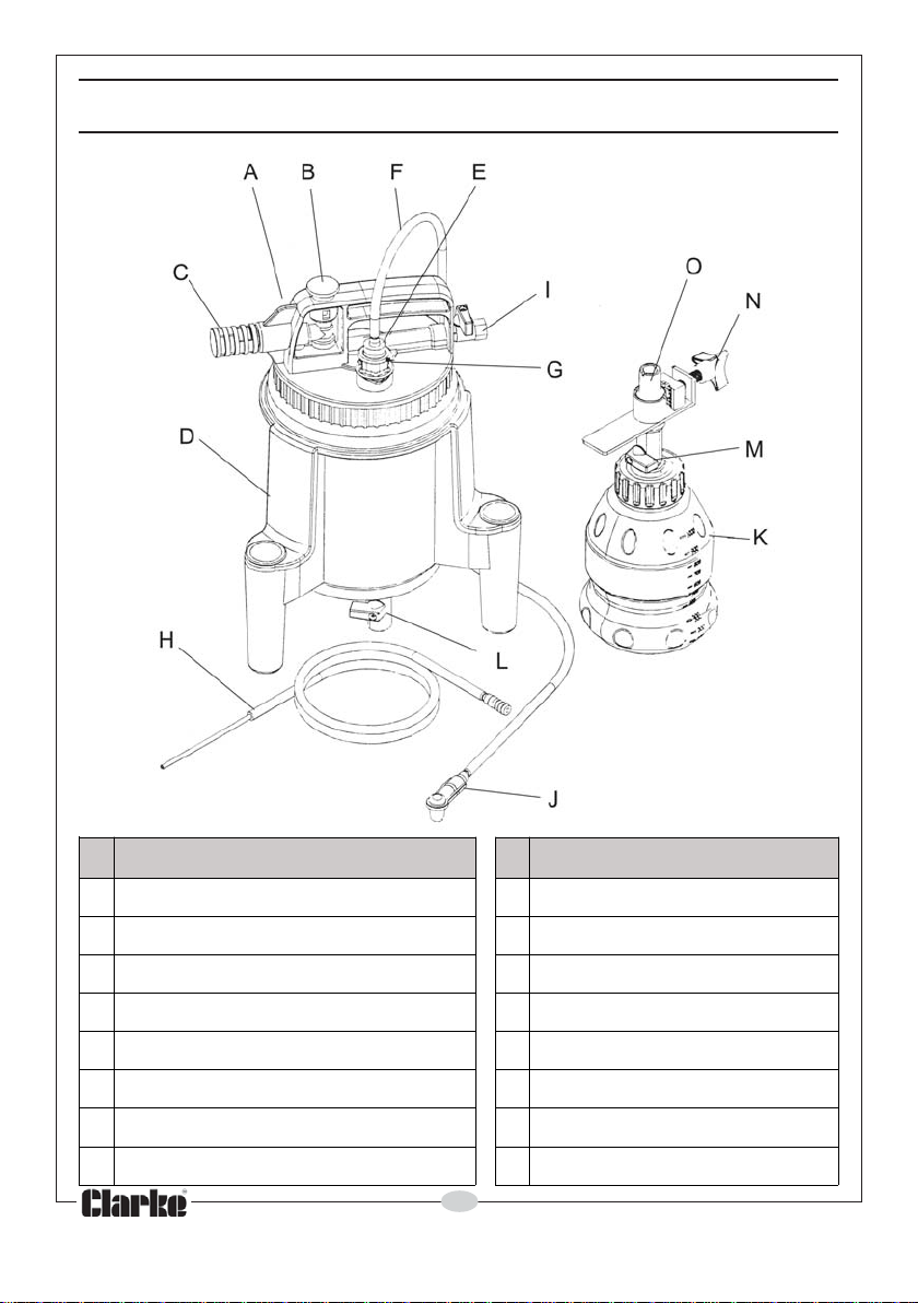
EQUIPMENT COMPONENTS
oN noitpircseD oN noitpircseD
AGNISUOHREVOCIEVLAVTELNIRIA
BNOTTUBHSUPJROTCENNOCDEELB
CRELFFUMKELTTOBGNILLIFERCITAMOTUA
DKNATLEVLAVNIARD
EEBUTTCARTXEROFRETPADAMEVLAVLLIFER
FEBUTDEELBNPMALCGNIRUCES
GGULPTELNIDIULFOELZZONLLIFER
HEBUTTCARTXEDIULF
6
Parts & Service: 020 8988 7400/E-mail:[email protected] or [email protected]
Page 7
PRINCIPAL OF OPERATION
The Clarke clutch & brake bleeding kit is designed for one-man operation. It is
used to drain brake fluid from a hydraulic system such as the clutch or brake
systems on an vehicle. It can also be used to extract a variety of fluids from
reservoirs including the master cylinders or those for power steering fluid.
It uses a normal workshop compressed air supply between 70 to 170 psi (4.8-
11.6 bar), to create a vacuum in the tank. The vacuum can be connected
by attaching the adapter to the fluid inlet plug located on the top of the unit.
The automatic refill bottle is designed for use with a standard bottle of brake
fluid, to maintain an adequate fluid level in the master cylinder while the
hydraulic system is bled. The bleeder air inlet will shut off automatically when
the hydraulic fluid reaches the maximum level.
OPERATING INSTRUCTIONS
IMPORTANT:
In addition to this manual, always follow the manufacturers recommended
procedures when servicing each vehicle.
REMOVING OLD HYDRAULIC FLUID FROM THE MASTER CYLINDER
1. Park the vehicle securely on level
ground with the engine off.
2. Clean the outside of the master
cylinder and master cylinder cap
to prevent dirt entering the
master cylinder when the cap is
removed.
3. Remove the cap from the master
cylinder reservoir.
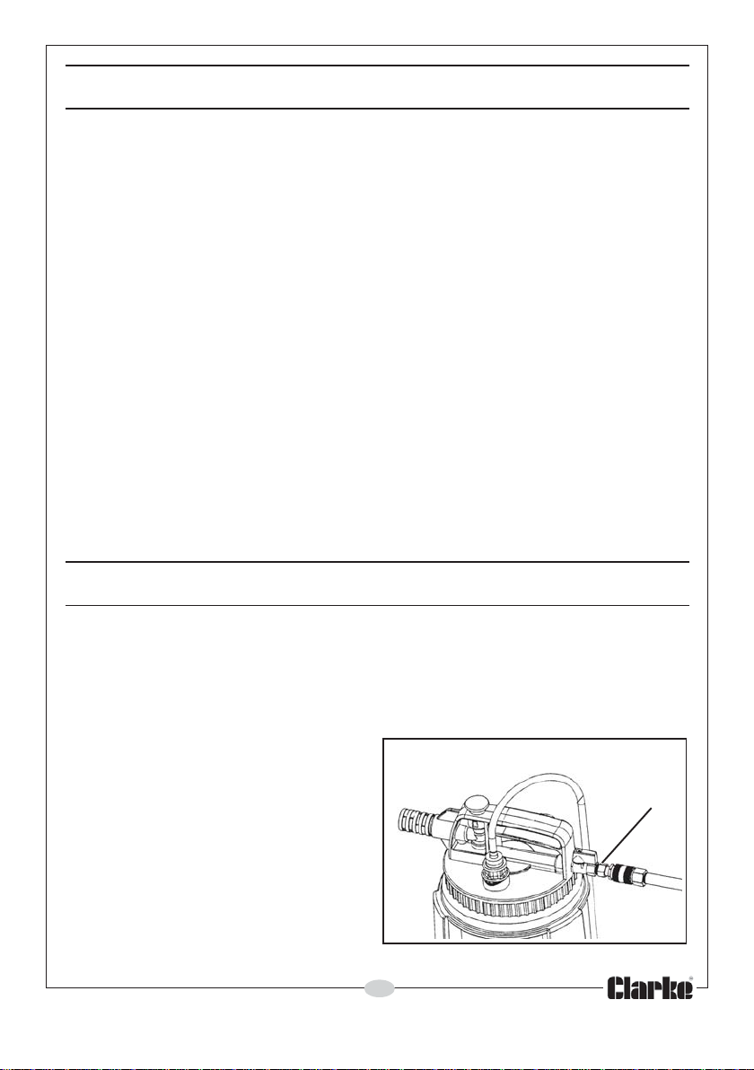
4. Connect compressed air supply
to the Air Inlet Valve (I).
7
Parts & Service: 020 8988 7400/E-mail:[email protected] or [email protected]
I
Page 8
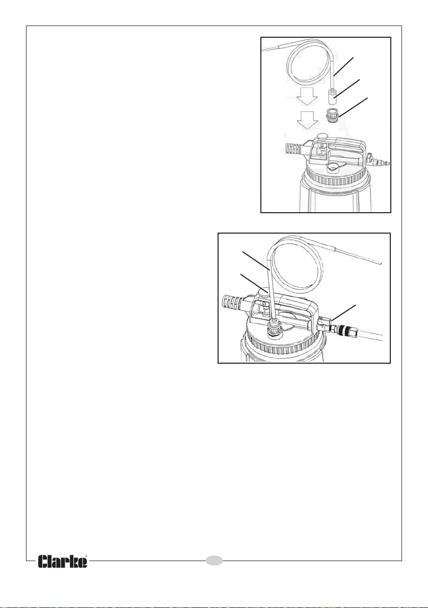
5. Connect the Extract Tube (H) to the Fluid
Inlet Plug (G) using the adaptor (E) .
H
E
G
6. Insert the free end of the Extract
Tube (H) into the master cylinder
on the vehicle.
7. Turn the air valve (I) on, if no air
flows through the unit then press
the Push Button (B) to create
the vacuum.
(Allow a few seconds for
vacuum to build in the bleeder
tank before suction occurs).
8. While extracting the old fluid,
agitate the fluid to dislodge and
remove any sludge that has
accumulated on the bottom
and walls of the master cylinder.
9. When all fluid has been removed, turn off the bleeder and refill the master
cylinder with the vehicle manufacturers recommended replacement
hydraulic fluid.
H
B
I
VACUUM BLEEDING HYDRAULIC LINES AND SLAVE CYLINDERS
Prior to bleeding, ensure that the master cylinder is full of the vehicle
manufacturers recommended replacement hydraulic fluid. The automatic
refill unit should be used to maintain the level of new fluid in the master
cylinder during the bleeding process. This will prevent air from being sucked
into the master cylinder, hydraulic lines and slave cylinders.
1. Park the vehicle securely on level ground with the engine off, for safe
access to the brake bleed screws located on each wheel brake cylinder
or to the clutch slave cylinder as required.
8
Parts & Service: 020 8988 7400/E-mail:[email protected] or [email protected]
Page 9
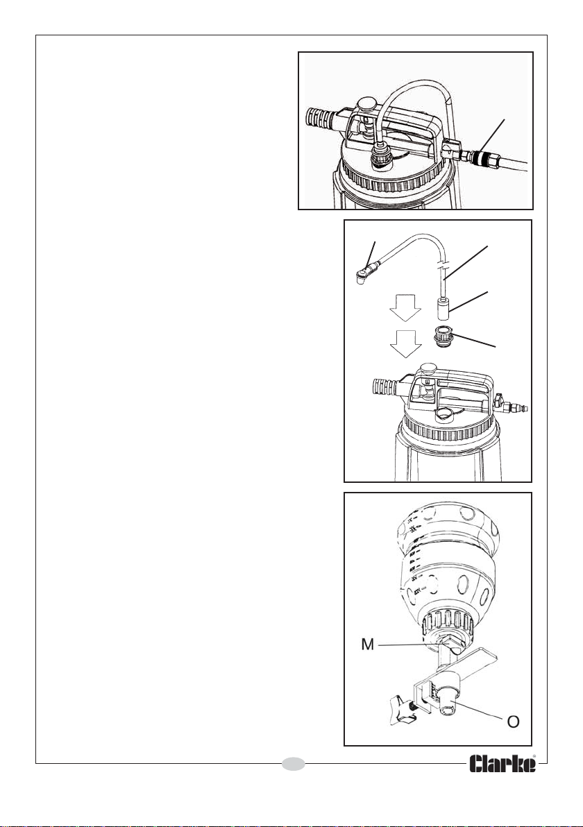
2. Make sure all the bleed screws
are clean.
3. Connect compressed air supply
to the Air Valve (I).
I
4. Connect the adaptor (E) of the Bleed
Tube (F) to the Fluid Inlet Plug (G).
Note: Consult the vehicle manufacturers
guidelines for the vacuum
bleeding procedure and any
specific wheel bleeding sequence.
5. Slip the Bleed Connector (J) located on
the opposite end of the Bleed Tube (F),
over the bleed screw nipple on the
vehicle.
6. Fill the refill unit with fresh hydraulic fluid
and secure it to the master cylinder with
the nozzle (O) immersed below the level
of the old fluid. Open the refill valve (M).
J
F
E
G
9
Parts & Service: 020 8988 7400/E-mail:[email protected] or [email protected]
Page 10
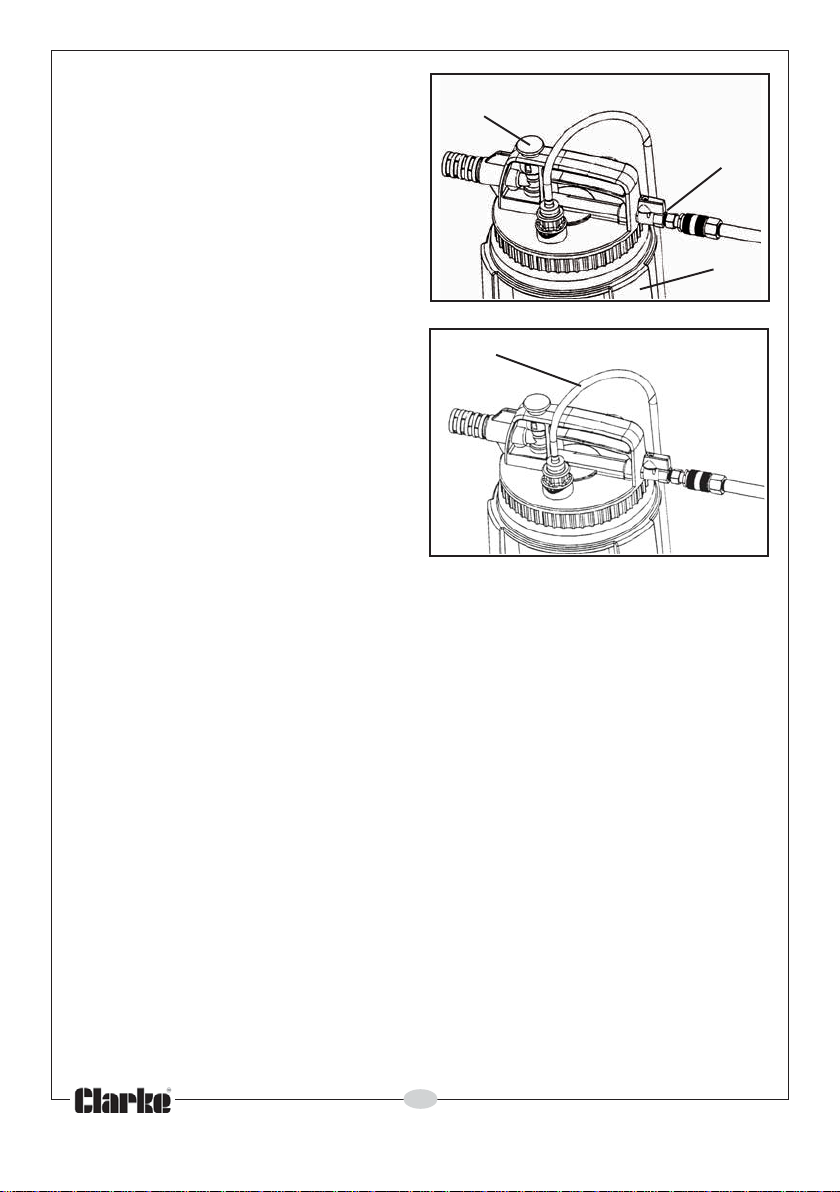
7. Turn the air valve (I) on, if no air
flows through the unit then press
the Push Button (B) to create the
vacuum.
Allow a few seconds for vacuum
to build in the bleeder tank
before suction occurs.
8. Using a wrench, loosen/open
the bleed screw slightly, until you
can see fluid draining through
the Bleed Tube and into the Tank
(D).
Note: During the bleeding process,
as hydraulic fluid is being drawn
through the bleed screw, air may
also be sucked into the bleed tube
from around the bleed screw
threads. This can give the
impression that air is bleeding from
the lines, however it is normal and
does not affect operation. To
prevent or reduce this kind of air
leak, coat the bleed screw threads
with silicon grease before bleeding.
9. Keep the bleed screw open until new fluid is visibly flowing through the
Bleed Tube (F) (typically 20 to 30 seconds).
10. Close the bleed screw firmly, without over tightening, prior to removing
the Bleed Tube from the vehicle and shutting off the unit.
11.Close the refill valve and remove the refill unit.
Note: It is important to ensure that the Bleed Tube connector remains
connected to the bleed screw, and the unit is still holding a vacuum while the
bleed screw is closed. This prevents air from being sucked back into the
brake or clutch slave cylinder from around the bleed screw threads before
the bleed screw is tightened and sealed.
Note: If the automatic refilling bottle is not used, be sure to periodically check
the level and top up the fluid in the master cylinder.
B
I
D
F
10
Parts & Service: 020 8988 7400/E-mail:[email protected] or [email protected]
Page 11
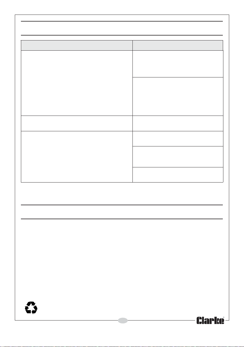
TROUBLESHOOTING
MELBORP NOITULOS
ottubeulbehtsserP
evlaVriAehtnehwtratstonlliwtinurotcartxE
ehtdnanoitisopNEPOehtotdenrutsi
.nwoddehsupsinottub
nehwyllacitamotuaffotuhsotsliafrotcartxE
el"lluf"ehtsehcaerknatehtnidiulfeht
lev
bgnitarepositinurotcartxeehT
.diulferomynaevomer
tonlliwtu
If you are still having difficulties with this product, contact your CLARKE
International Service Department on 020-8988-7400.
.tluaf
ylmrifsiebutehttahtkcehC
snidiulfehttahtkcehC
.noitisoplevel
.devomer
revocehtnon
,draehsidnuoskcilcehtfI.gnisuoh
asierehttonfitubdnuossitinueht
edispuydobtinuehtgnidnatsyrT
.diulfehtotdetcennoctonfinwod
taydobehtnael,diulfgniniatnocfI
sserP.semitlarevesekahs,ged54
idnuos"kcilc"ehtfidnanottubeht
s
.lamronsignihtyrevenehtdraeh
,gnideelbpotsotevlavriaehtesolC
.diulfdesuehtfoesopsidneht
.tuodeppilstondnadetacol
ehtedi
"lluF"ehtdehcaersahrotcartxe
neebsahdiulfehtllatahtmrifnoC
MAINTENANCE
No maintenance is required but always drain, wash and clean the unit after
each use. Never clean the unit with aggressive detergents or chemicals.
Always store both the main unit and connecting tubes in a dry place which is
not exposed to direct sunlight or extremes of temperature.
ENVIRONMENTAL PROTECTION
One of the most damaging sources of environmental pollution is oil products.
Never throw away used hydraulic oil with domestic refuse or flush it down a
sink or drain. Collect all the hydraulic oil in a leak proof container and take it
to your local waste disposal site.
Do not dispose of this product with general household waste. All tools,
accessories and packaging should be sorted, taken to a recycling
centre and disposed of appropriately.
11
Parts & Service: 020 8988 7400/E-mail:[email protected] or [email protected]
Page 12
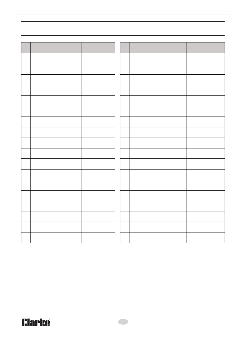
PARTS LIST - EXTRACTION UNIT
oN noitpircseD oNtraP oN noitpircseD oNtraP
1
2NOTTUBHSUP20736THCTH02MRA02736THCTH
3
4
5
6
7
8
9
01
11GNIR-O11736THCTH92GNISUOHTELNIDIULF92736
21
31
41
51
61
71
GNIRPS30736THCTH12GNISUOHEVL
GNIR-O50736THCTH32EVLAVTELTUODIULF32736THCTH
GNIR-O60
RELFFUM90736THCTH72TUNKCOL72736THCTH
GNIR-O01736THCTH82GNIR-O82736THCTH
TFAHS21736THCTH03GNIR-O03736THCTH
GNIR-O31736THCTH13REVOCTELNIDIULF13736THCTH
GNIRPS41736THCTH23ROTPADA2
GNIR-O51736THCTH33EVLAVRIA33736THCTH
NIP61736THCTH43GNITTIF&EBUTEKARB43736THCTH
TAOLF71736THCTH53EB
GNISUOHREVOC100736THCTH91GNIR-O91736THCTH
AVYTEFAS12736THCTH
EVLAVMUUCAV40736THCTH22WERCS22736THCTH
736THCTH42PACGEL42736THCTH
YDOBMUUCAV70736THCTH52KNAT52736THCTH
TRESNIRELFFUM80736THCTH62GNIKCAP62736THCTH
LLEHS
UTTCARTXE53736THCTH
THCTH
3736THCTH
81
PUCYTEFAS81736THCTH63GNIR-O63736THCTH
IMPORTANT: The use of parts other than genuine CLARKE replacement parts
may result in safety hazards, decreased performance, and will invalidate your
warranty.
12
Parts & Service: 020 8988 7400/E-mail:[email protected] or [email protected]
Page 13
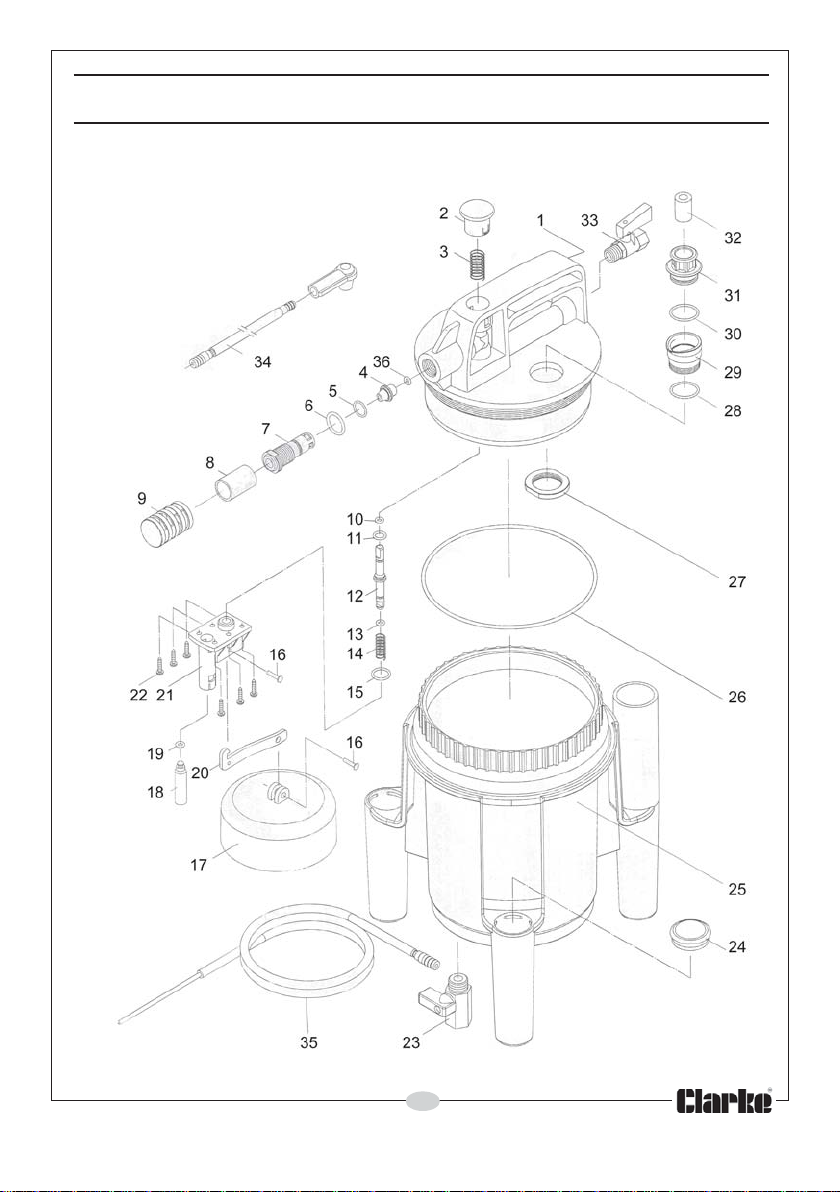
PARTS DIAGRAM - EXTRACTION UNIT
13
Parts & Service: 020 8988 7400/E-mail:[email protected] or [email protected]
Page 14
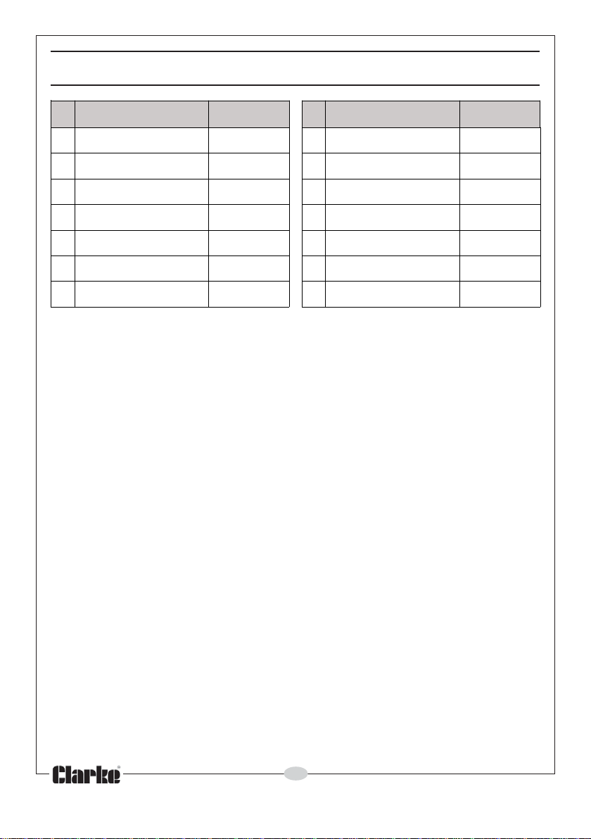
PARTS LIST- REFILLING BOTTLE
oN noitpircseD oNtraP oN noitpircseD oNtraP
1
2DIL83736THCTH
3
4
5
6
7
ELTTOB73736THCTH
GNIKCAP93736THCTH
LAV04736THCTH11WERCS74736THCTH
EV
TUNKCOL14736THCTH
TEKCARB24736THCTH
TEKCOSLEVIWS34736THCTH
8
9
01
21
31
ELZZON44736THCTH
BONK54736THCTH
REHSAW64736THCTH
ETALP84736THCTH
KCOLBGNITNUOM94736THCTH
14
Parts & Service: 020 8988 7400/E-mail:[email protected] or [email protected]
Page 15
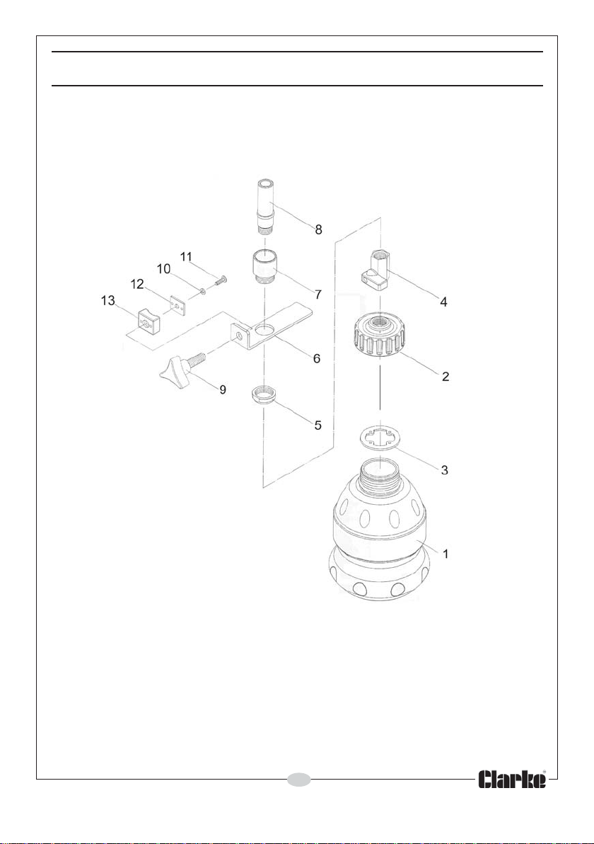
PARTS DIAGRAM - REFILLING BOTTLE
15
Parts & Service: 020 8988 7400/E-mail:[email protected] or [email protected]
Page 16
 Loading...