

Page 1
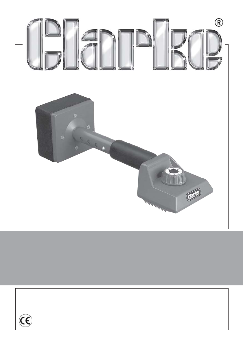
CARPET KNEE KICKER
Model:CHT403
Part No: 1801403
OPERATING & MAINTENANCE
INSTRUCTIONS
GC02/12
Page 2

Page 3
Please read these instructions carefully before using the tool
Thank you for purchasing this CLARKE Carpet Knee Kicker
Before using the device, please read this manual thoroughly and carefully
follow all instructions given. This is for your own safety and that of others
around you, and is also to help you achieve long and trouble free service
from your new tool.
GUARANTEE
This CLARKE product is guaranteed against faulty manufacture for a period of
12 months from the date of purchase. Please keep your receipt as proof of
purchase.
This guarantee is invalid if the product is found to have been abused or
tampered with in any way, or not used for the purpose for which it was
intended.
Faulty goods should be returned to their place of purchase, no product can
be returned to us without prior permission.
This guarantee does not affect your statutory rights.
SPECIFICATIONS
Model: CHT403
Part No: 1801403
Overall Length: 470 - 545mm
FEATURES
• Teeth Depth Adjustment
• Overall length Adjustment
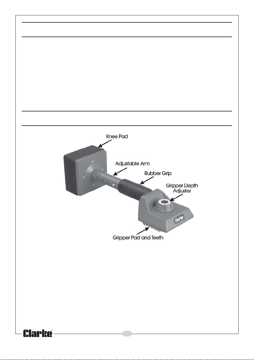
This Carpet Kicker allows you to manoeuvre the carpet into its final position
and ‘knee-kick’ the edge onto the gripper rail with ease and precision.
It is suitable for use with carpets that are intended to be fitted by means of a
gripper rail. You should check to ensure that your carpet may be fitted using
a carpet kicker.
3
Parts & Service: 020 8988 7400/E-mail:[email protected] or [email protected]
Page 4
SAFETY PRECAUTIONS
SAFETY PRECAUTIONS
Important;- Failure to follow these precautions could result in personal injury,
and/or damage to property.
Failure to follow these precautions could result in personal injury, and/or damage to
1. Take care handling the kicker. The head has sharp blades and teeth.
2. Never leave the kicker with the gripper pad and teeth facing upwards
when the safety cover is not fitted.
3. ALWAYS concentrate on the job in hand, no matter how trivial it may
seem. Be aware that accidents are caused by carelessness due to
familiarity.
IMPORTANT
property.
PREPARATION FOR USE
The Carpet Kicker is used for the final fitting of a carpet, and the following
conditions are therefore assumed to be in effect.
1. The gripper rail has been correctly positioned around the edges of the
room and properly secured to the floor.
2. The underlay has been laid and secured to the floor in the area bounded
by the gripper rail.
3. The carpet has been cut oversize according to the required room shape.
4. The carpet has been correctly orientated and placed approximately in
position in the room where it is to be laid.
5. The carpet has been spread out in the room so that it is flat to the
underlay.
4
Parts & Service: 020 8988 7400/E-mail:[email protected] or [email protected]
Page 5
The length of the kicker can be adjusted to best suit the user’s preference
and working space.
The teeth can be set to protrude to a depth to best suit the thickness of the
carpet to be fitted.
The protection cover should always be fitted when the kicker is not in use and
should be left in place whilst adjusting the kickers’ length. The teeth must be
retracted (setting 0) for the cover to be fitted. Keep the cover handy for reuse during the job.
To remove the cover, grip it and pull it away from the kicker head.
LENGTH ADJUSTMENT
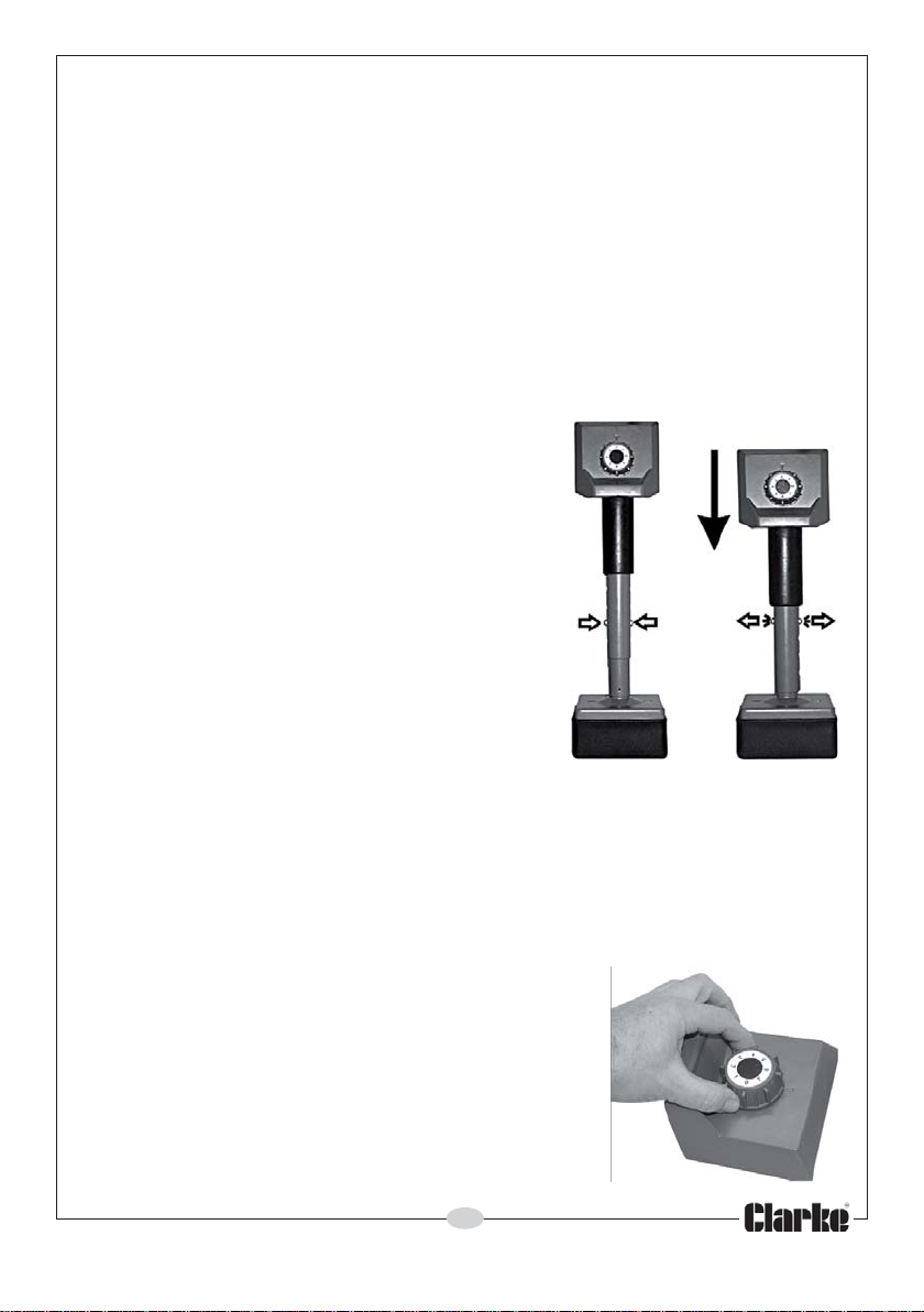
The telescopic steel tube is locked by means of
spring pins. The captive pins lock the tubes in
position through holes in the tubes. There are
two locking pins. These allow the kicker to be
adjusted in length from 470 mm to 545 mm (18½
to 21½ inches).
To adjust the length:
1. Press the two pins inwards and hold them in
this position whilst rotating one tube so the
pins are out of alignment so they remain
depressed.
2. Adjust to the required length by moving the
ends of the kicker closer together or further
apart, as required, then rotate the tubes
until the holes and pins are realigned. The
pins will spring out and lock the tubes in position.
TEETH DEPTH ADJUSTMENT
The teeth depth may be adjusted by means of the rotary depth control knob.
There are eight settings, 0 to 7. The lowest setting is ‘0’ for thin pile carpets. The
maximum setting is ‘7’ for deep pile carpets.
Determine the teeth depth required for the carpet
to be laid.
To do this, test on an off-cut of carpet to ensure
teeth depth selection is correct.
The teeth should be adjusted to grip the base
material of the carpet and not to pierce it, as this
could damage the underlay.
Rotate the adjuster knob to raise or lower the
teeth.
Parts & Service: 020 8988 7400/E-mail:[email protected] or [email protected]
5
Page 6
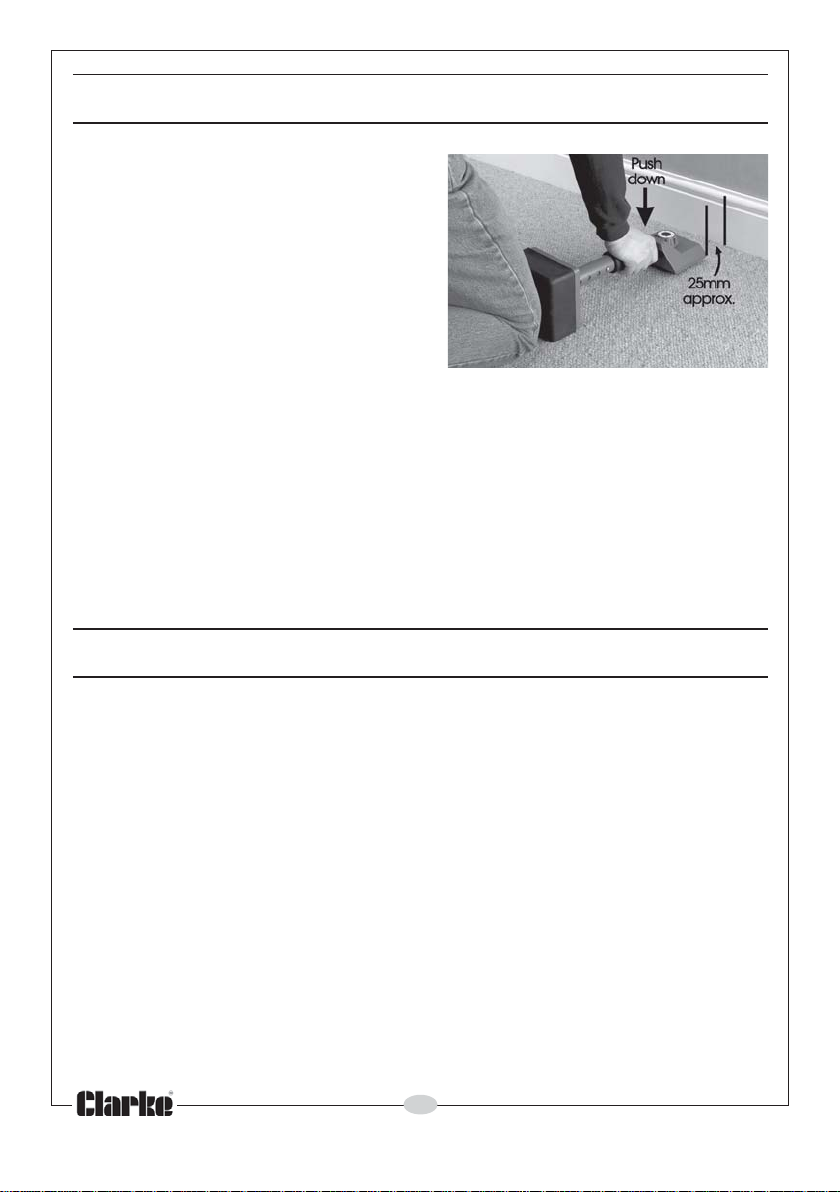
METHOD OF USE
1. Set the teeth to a depth to suit the
carpet thickness, as described
previously.
2. Kneel close to one corner of the
longest edge of the carpet and
place the kicker about 25 mm from
the edge of the gripper rail and
facing the skirting board.
3. Sink the teeth into the carpet and
apply reasonable downward
pressure on the handle-grip.
4. Use your knee to ‘kick’ the padded end of the kicker so as to jog the
carpet forward, whilst pushing down on the edge of the carpet so that it is
held by the carpet gripper
5. Work your way along this edge repeating the operation, then cut and
tuck the carpet edge between the gripper rail and skirting board.
6. Repeat along the opposite edge of the carpet other edges as required.
7. If in doubt about the fitting procedure please contact an experienced
fitter.
MAINTENANCE
The only maintenance required is to ensure that after use, any carpet pile
that may have attached itself to the gripper pad is completely removed, and
the Kicker is stored with the grippers teeth protection cover in place.
Gripper teeth and Gripper Blade pad assemblies are available from your
CLARKE dealer - please see ‘SPARE PARTS’ for details.
RENEWING A GRIPPER PAD ASSEMBLY
Two gripper blade pad assemblies are each secured in place with two
screws.
Firstly, remove each Gripper Blade Pad assembly as follows:
1. Turn the teeth setting knob fully clockwise so that the teeth are fully
retracted.
2. Undo the two screws using a cross-head screwdriver.
3. Lift off the assembly.
6
Parts & Service: 020 8988 7400/E-mail:[email protected] or [email protected]
Page 7
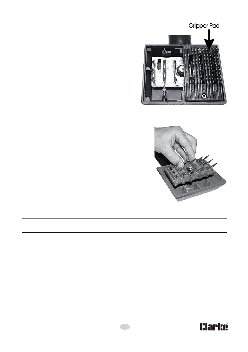
Replace the pads, ensuring the blade
points face away from the padded end
and is fully and properly seated in the
recess.
Refit the screws and tighten using a crosshead screwdriver.
REMOVING THE TEETH BLOCK
To remove the Teeth Block, firstly remove the
gripper pads as described previously, then,
using a protective glove or similar to hold the
teeth block, rotate the teeth setting adjuster
knob anticlockwise until it becomes fully
disengaged from the adjuster assembly, then
lift it free.
Replace in reverse order, screwing the adjuster
knob clockwise fully, until the ‘0’ on the knob
dial aligns with the marker on the body.
Finally, refit the gripper pads as described
above.
SPARE PARTS
The following parts are available:
• Teeth Assembly Part No: CHT40101
• Gripper Blade Pad Assembly Part No: CHT40102
• Gripper Blade fixing screws (x2) Part No: CHT40103
7
Parts & Service: 020 8988 7400/E-mail:[email protected] or [email protected]
Page 8
 Loading...