

Page 1

Electronic Service
Manuals
This electronic document is provided as a service to our customers.
We do not create the contents of the information contained in this document. Should you have detailed questions pertaining to the information
contained in this document, you may contact Michco, or the manufacturer which provided the original information in this electronic deliverable. Michco’s only part in this electronic deliverable was the electronic
assembly process. By providing this manual on line we are not guaranteeing parts availability.
You may contact Michco through the following methods:
Phone (517) 484-9312 or (800) 331-3339
2011 N. High St. -- Lansing, Michigan -- 48906
Fax: (517) 484-9836
Email: [email protected]
Web site: www.Michco.Com
Parts Web site: www.FloorMachineParts.Com
Order Parts on Line at:
www.FloorMachineParts.Com
Directly to Parts & Service:
By Email: [email protected]
By Fax: (517) 702-2041
By Voice: Use numbers above.
Serving the Cleaning Industry Since 1922
Notice: All copyrighted material remains property of original owners, all trademarks are property of respective owners.
Manuals are subject to Manufacturer’s reproduction limitations. Originals or reproductions were provided by manufacturers
through a request. We make no warranty as to the correctness of information provided in this document and you assume
all risk. By placing these manuals on line we are not declaring our corporation to be an manufacturer authorized dealer or
provider, please check our web site for authorized manufacturers we represent.
Page 2
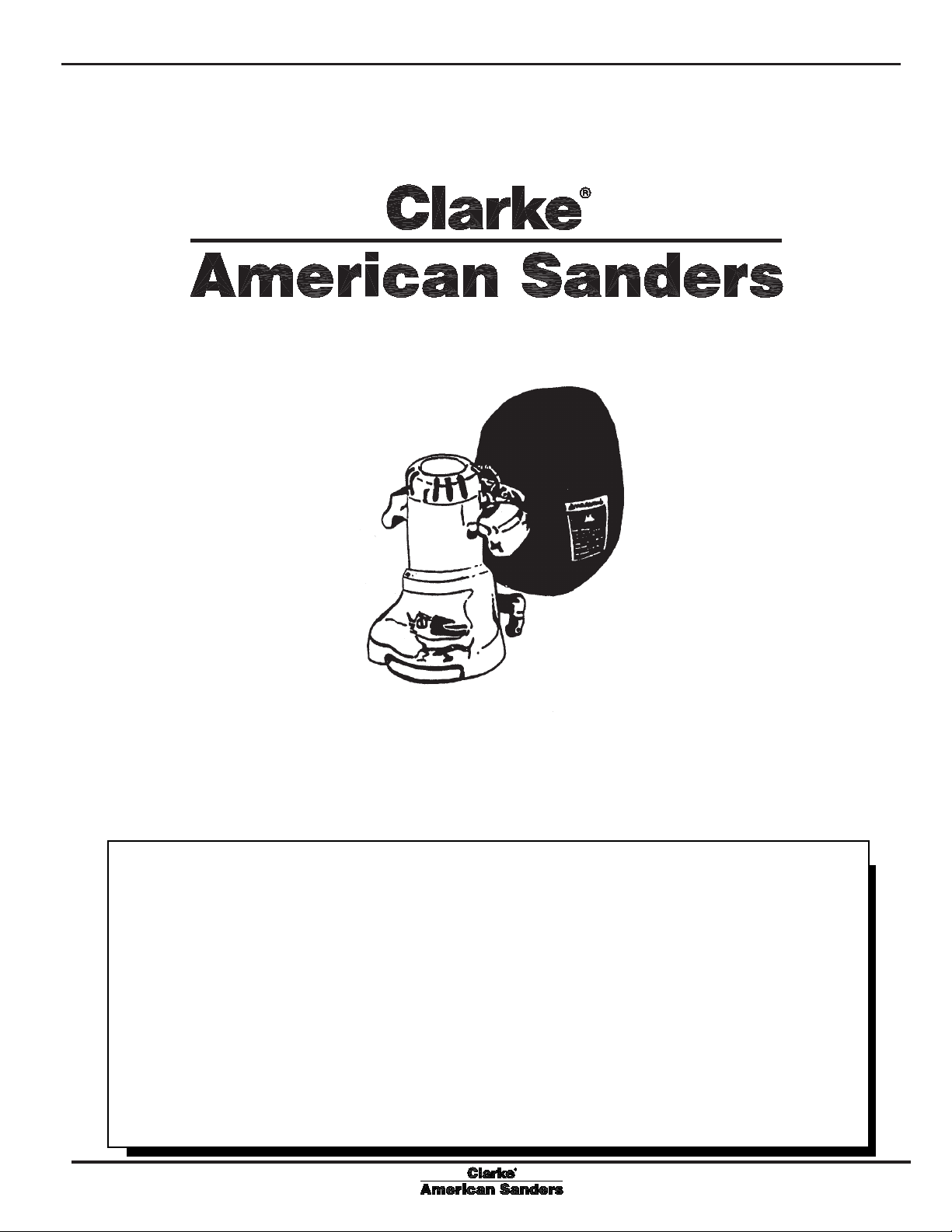
B2B2
B2
B2B2
Operator's
7" Spinner7" Spinner
7" Spinner
7" Spinner7" Spinner
Manual
Edger (CE)Edger (CE)
Edger (CE)
Edger (CE)Edger (CE)
MODEL: 07097A
READ THIS BOOK
This book has important information for the use and safe operation of this machine. Failure to read
this book prior to operating or attempting any service or maintenance procedure to your Clarke
American Sanders machine could result in injury to you or to other personnel; damage to the machine
or to other property could occur as well. You must have training in the operation of this machine
before using it. If your operator(s) cannot read English, have this manual explained fully before
attempting to operate this machine.
Si Ud. o sus operadores no pueden leer el Inglés, se hagan explicar este manual completamente
antes de tratar el manejo o servicio de esta máquina.
All directions given in this book are as seen from the operator’s position at the rear of the machine.
Form No. 70162B 12/06 revised 11/10
Page 3

Contents of this Book
Operator Safety Instructions .........................................................3
Introduction and Machine Specifications.......................................5
Machine Set-Up ...........................................................................6
How to Operate the Machine ........................................................8
Sanding Cuts and Sandpaper .................................................... 9
Maintenance ..............................................................................10
The Dust Control System ......................................................10
How to Adjust the Angle of the Sandpaper Disc to the Floor..10
How to Change Adjustment of Machine.................................10
How to Clean Ventilation Plug...............................................10
Lubrication............................................................................11
revised 5/10
How to change the Lubricant in the Gearbox .........................11
How to Check the Carbon Brushes .......................................11
Assembly Drawing #1 ................................................................14
Assembly Parts List #1 ..............................................................15
Assembly Drawing #2 ................................................................16
Assembly Parts List #2 ..............................................................17
Wiring Diagram..........................................................................18
W ARNING!
The Products sold with this Manual contain or may contain chemicals that are known to certain governments (such as the State of
California, as identified in its Proposition 65 Regulatory Warning Law) to cause cancer, birth defects or other reproductive harm. In
certain locations (including the State of California) purchasers of these Products that place them in service at an employment job site or a
publicly accessible space are required by regulation to make certain notices, warnings or disclosures regarding the chemicals that are or
may be contained in the Products at or about such work sites. It is the purchaser’s responsibility to know the content of, and to comply
with, any laws and regulations relating to the use of these Products in such environments. The Manufacturer disclaims any responsibility
to advise purchasers of any specific requirements that may be applicable to the use of the Products in such environments.
- 2 - FORM NO. 70162B Clarke® American Sanders B-2 (CE) Operator's Manual
Page 4
OPERATOR SAFETY INSTRUCTIONS
WARNING AVERTISSEMENT ADVERTENCIA
DANGER means: Severe bodily injury or death can occur to you or other personnel if the DAN-
GER statements found on this machine or in this Operator's Manual are
ignored or are not adhered to. Read and observe all DANGER statements
found in this Operator's Manual and on your machine.
WARNING means: Injury can occur to you or to other personnel if the WARNING statements
found on your machine or in this Operator's Manual are ignored or are not
adhered to. Read and observe all WARNING statements found in this
Operator's Manual and on your machine.
CAUTION means: Damage can occur to the machine or to other property if the CAUTION state-
ments found on your machine or in this Operator's Manual are ignored or are
not adhered to. Read and observe all CAUTION statements found in this
Operator's Manual and on your machine.
DANGER: Failure to read the Operator's Manual before operating or servicing this sanding equipment
could result in injury to the operator or to bystanders and could cause damage to the
equipment. Read and observe all safety statements found in this manual and on the
sanding equipment. Make sure all labels, decals, warnings, cautions and instructions are
fastened to the equipment. Replace any that are damaged or missing. You must have
training in the operation of this equipment before using it. If the operator is unable to
read this manual, have it explained fully before they attempt to use this equipment.
DANGER: Sanding/finishing wood floors can create an environment that can be explosive. The
following safety procedures must be adhered to:
• Cigarette lighters, pilot lights and any other source of ignition can create an explosion
when active during a sanding session. All sources of ignition should be extinguished or
removed entirely if possible from the work area.
• Work areas that are poorly ventilated can create an explosive environment when certain
combustible materials are in the atmosphere, i.e., solvents, thinners, alcohol, fuels,
certain finishes, wood dust and other combustible materials. Floor sanding equipment
can cause flammable material and vapors to burn. Read the manufacturer's label on all
chemicals used to determine combustibility. Keep the work area well ventilated.
• Spontaneous combustion or an explosion can occur when working with sanding dust.
The sanding dust can self-ignite and cause injury or damage. Sanding dust should be
disposed of properly. Always empty the sanding dust into a metal container that is
located outside of any building(s).
• Remove the contents of the dust bag when the bag is 1/3 full. Remove the contents of
the dust bag each time you finish using the equipment. Never leave a dust bag unattended with sanding dust in it.
• Do not empty the contents of the dust bag into a fire.
• Hitting a nail while sanding can cause sparks and create an explosion or fire. Always
use a hammer and punch to countersink all nails before sanding floors.
®
Clarke
American Sanders B-2 (CE) Operator's Manual FORM NO. 70162B - 3 -
Page 5
DANGER: Operating partially assembled sanding equipment could result in injury to the operator or
bystander and could cause damage to the equipment or to other property.
• Do not operate this equipment unless it it fully assembled and all guards, doors and
covers are secured.
• Keep all fasteners tight.
• Keep all adjustments within manufacturers specifications.
DANGER: Moving parts on this sanding equipment can cause injury to the operator or bystanders.
• Keep hands, feet and loose clothing away from all moving parts.
• Do not change or adjust the abrasive while the sanding equipment is running.
• Do not service the sanding equipment while it is running.
DANGER: This sanding equipment requires a supply of electricity. Improper use could result in electrical
shock or fire.
• Connect only to an electrical source matching what is shown on the equipment nameplate.
• Do not use this sanding equipment on an ungrounded electrical circuit. Consult an
electrician if you suspect the circuit is not properly grounded.
• Do not use this sanding equipment with a damaged electrical cord. Inspect before each
use.
• Avoid striking the elelctrical cord with the abrasive. Always lift the electrical cord over
the sanding equipment.
• Do not use the electrical cord to move the sanding equipment.
• Disconnect the electrical source before servicing this equipment.
WARNING: Injury to the operator or bystander can occur if protective gear is not worn while sanding.
Always use eye, ear, and respiratory protection while performing any sanding operation.
WARNING: Bodily injury could occur if power is applied to the equipment with the power switch already
in the "ON" position. Always check to assure that the power switch is in the "OFF" position
before connecting power supply.
CAUTION: Maintenance and repairs performed by unauthorized personnel could result in damage or
injury. Maintenance and repairs performed by unauthorized personnel will void your warranty.
Servicing of this unit must always be referred to an authorized Clarke American Sanders
distributor.
CAUTION: Use of this equipment to move other objects or to climb on could result in injury or damage.
Do not use this equipment as a step or furniture. Do not ride on this equipment.
CAUTION: Damage could occur to the equipment if not properly kept in a dry building for storage. Store
the equipment in a dry building.
CAUTION: Serious damage to the floor can occur if the sanding equipment is left running in one spot while
the sanding disc is in contact with the floor. To avoid damage to the floor, do not dwell while
lowering or raising the sanding disc. Always sand with a constant motion.
- 4 - FORM NO. 70162B Clarke® American Sanders B-2 (CE) Operator's Manual
Page 6
INTRODUCTION AND MACHINE SPECIFICATIONS
revised 5/10
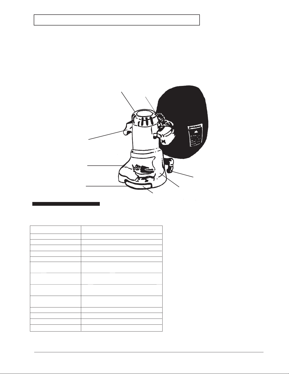
The B-2 is specifically designed for finishing floor edges, stairs, and other hard-to-reach surfaces. The handle
location and low center of gravity make the B-2 easy to operate.
The excellent cutting power comes from a powerful universal type motor. A motor that delivers maximum
performance without slowing down or overheating. Its exclusive two speed control when switched to hi-speed
produces 3200 rpm for fast, rough sanding. At low speed, the B-2 operates at 2800 rpm for fine, finish sanding.
A non marking disc guard protects the rubber pad, permitting the edger to work right up to the baseboard or wall.
Powerful Universal Motor
High Low Switch
Comfortable Operating
Handles
Aluminum Alloy Casting
Balanced Sanding Disc
for perfectly matched job
Non-Marking Roller Guard
Specifications
Voltage/Frequency 220V-240 /50-60 Hz
Amperage 6.5
Motor 1450W (1 HP)
Sound Level 91dB (A)
Vibration 5.7 m/s
2
rms
Abrasive Size 178mm x 22 mm Dia. (7" x 7/8" Dia.)
Disc Rate High 3200 RPM
Disc Rate Low 2800 RPM
Gears Hardened steel alloy pinion
and drive gear.
Bearings Sealed ball bearings,
lifetime lubricated.
Dust Collector Powerful vacuum fan, full
aluminum skirt
Power Cord 12m H07RN F3G 1.5mm
2
Dimensions 356 x 260 x 343mm (14 x 10½ x 13½)
Weight 14.5 kg (32 lbs)
Shipping Weight 21 kg (46 lbs)
Non-Marking Swivel Type
Casters
Powerful Vacuum Fan for effecient dust pickup
®
Clarke
American Sanders B-2 (CE) Operator's Manual FORM NO. 70162B - 5 -
Page 7
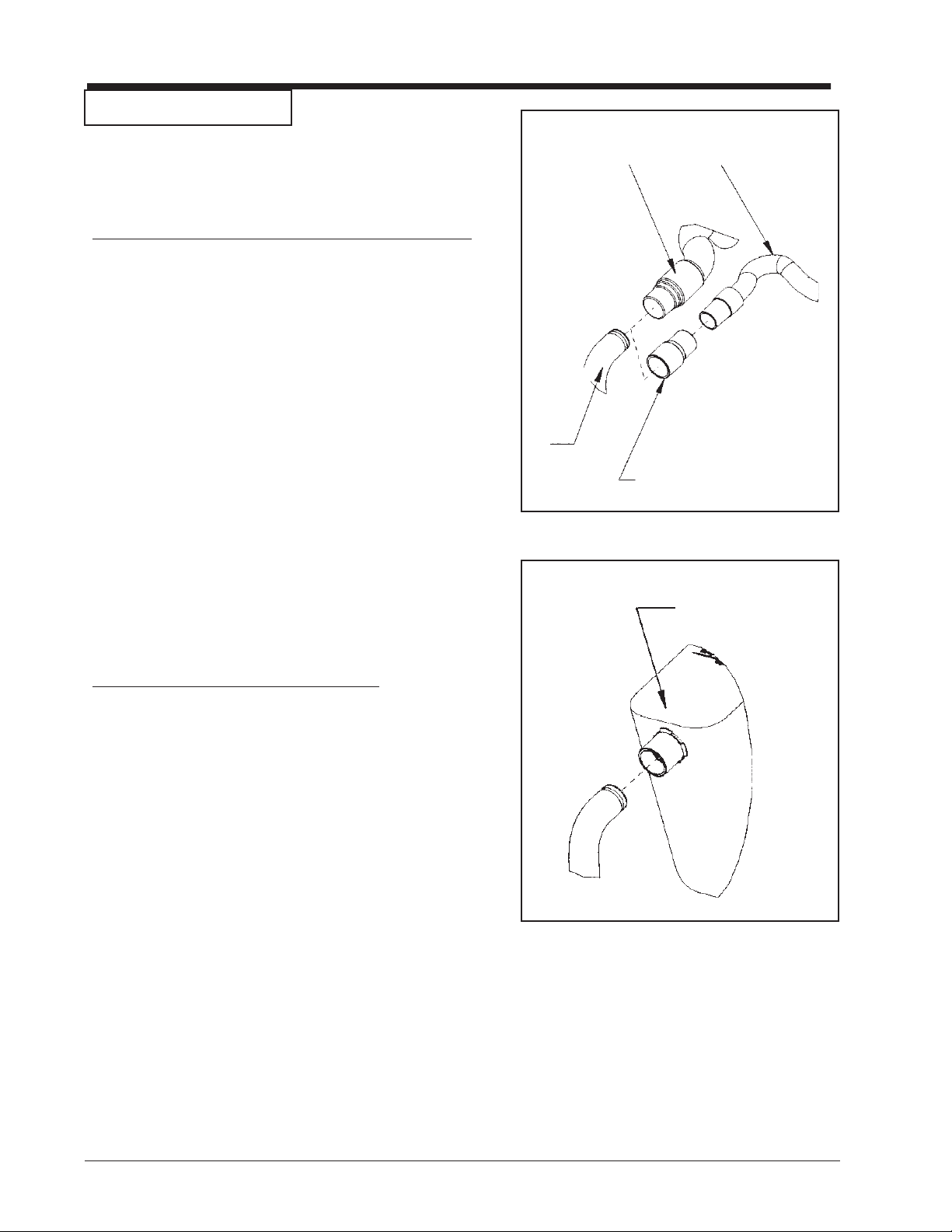
Machine Set-up
This sanding machine is designed to be operated with a
remote vacuum dust collection sytem or with the included
dust bag.
Preparing Remote Vacuum Dust Collection Sytems
To prepare the machine for remote vacuum dust collection
systems that have a 2" hose end, follow this procedure:
1. Install 2" hose end (figure 1, A) directly over the
exhaust tube (figure 1, B).
2. The exhaust tube can be rotated for optimum convenience.
2" Hose from
vacuum system
(not included)
1.5" Hose from
A
D
vacuum system
(not included)
To prepare the machine for remote vacuum dust collection
systems that have a 1 ½" hose end, follow this procedure:
1. Install the 2" x 1½" hose end adaptor (Part No.
30563A) (figure 1, C) over the exhaust tube (figure 1,
B).
2. Insert 1 ½" hose end (figure 1, D) into the adaptor
(figure 1, C).
NOTE: Start the remote vacuum collection system
before operation.
Preparing to use the included dust bag
To prepare the machine for use with the included dust bag
(Part No. 53544B), follow this procedure:
1. Install the dust bag by pressing the end onto the
exhaust tube until the ring locks into the groove (figure
2). This is best done by pressing on the back of the
bag opening with the palm of your hand.
2. The exhaust tube can be rotated for optimum convenience.
B
Exhaust Tube
C
(30563A) 2" Tube x 1.5" hose adaptor
Figure 1
Install the dust bag by
pressing the end onto the
exhaust tube until the ring
locks into the groove.
3. To remove the dust bag from the exhaust tube, pry up
the end of the bag opening to partially release the
Figure 2
internal rib from the groove, then pull.
4. To empty the dust bag, unzip the disposal flap and
force contents out by inverting the bag.
NOTE: For best results, empty frequently. Follow all
warnings posted in this manual and on the dust bag.
- 6 - FORM NO. 70162B Clarke® American Sanders B-2 (CE) Operator's Manual
Page 8
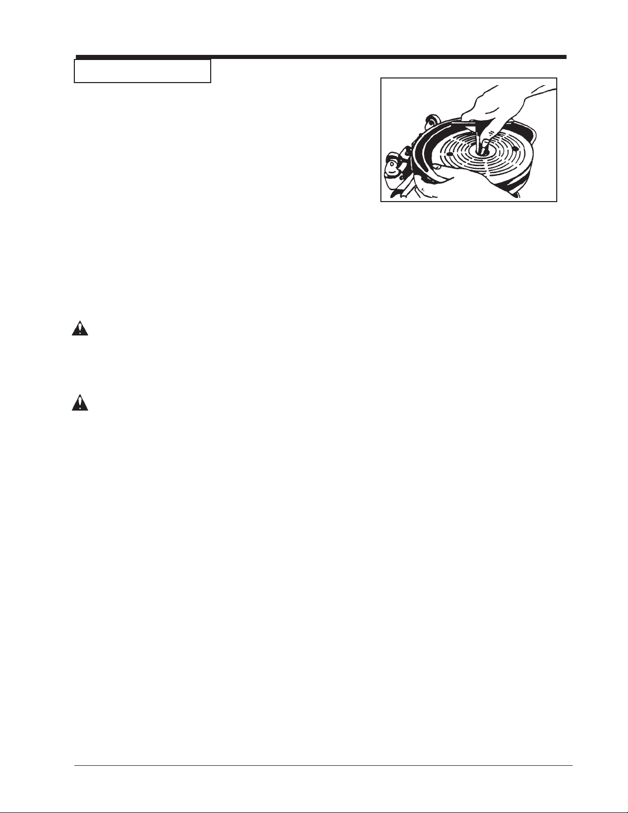
MACHINE SET-UP
To prepare the machine for use, follow this procedure:
1. Familiarize yourself with the machine. Read all
danger, warning and caution statements and the
Owner's Manual. If operator is unable to read English,
have the manual explained before operating.
2. To install or replace abrasive, turn the machine upside
down and let it rest on the motor cover. With the
wrench supplied, remove the screw and abrasive
retainer. Hold pad to prevent it from rotating and turn
wrench. See figure 3.
3. Center abrasive on pad and install the abrasive retainer
and screw. Tighten screw.
4. Return machine to upright position.
WARNING: Serious injury could occur when attempting
to replace abrasive while machine is
connected to power supply. Always
disconnect power before installing abrasive.
Figure 3
CAUTION: Gearbox damage could result from machine
resting upside down for extended periods
of time. Lubricant may drain from gearbox.
Always return machine to upright position
after installing abrasive.
®
Clarke
American Sanders B-2 (CE) Operator's Manual FORM NO. 70162B - 7 -
Page 9
OPERATING INSTRUCTIONS
To operate the machine, follow this procedure:
1. Set any exposed nails with a hammer and punch to
avoid encounter with sanding pad.
2. Connect the machine to an appropriately grounded and
fused circuit (power supply).
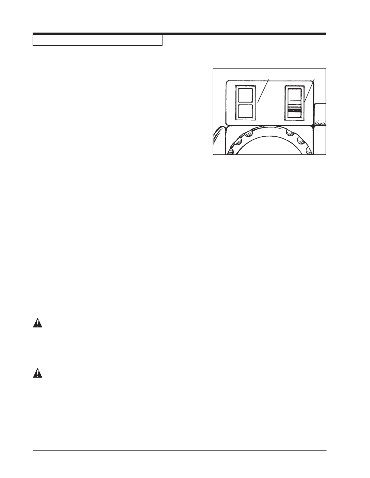
3. Tilt the machine back so that the sanding pad does not
contact the floor. Select cutting speed. Use high
speed for fast stock removal. Use low speed for finish
cuts and custom work. See
figure 4 (A).
4. Depress and release the start/stop push button to start
the machine. See figure 4 (B).
5. Gradually lower sanding pad to the floor. Make sure
the machine is in motion while the sanding pad is
engaged with the floor. Broad circular motions can be
used as you sand along the length of the floor or you
may use a combination of forward and sideway
motions. In time you will develop your own technique
to optimize coverage and dust control. It is advisable
to not add effort to the pad as this may lead to
"nosing" or "tipping" which produces grooves or lines
on the floor.
B
Figure 4
A
6. When replacing abrasive; emptying the contents of the
dust bag; or the sanding operation is completed, return
the machine to the reclined position and flip the control
switch to the off (O) position. Disconnect the machine
from the power supply.
7. Empty dust bag whenever it becomes 1/3 full.
DANGER: Failure to disconnect the supply cable from
machine whenever servicing, replacing
abrasive, or emptying the dust bag could
result in electrocution or severe injury.
Never leave machine unattended while the
supply cable is connected.
DANGER: Never leave dust bag unattended with
sanding dust in it. Sanding dust can
spontaneously ignite and cause a fire or
explosion. Empty dust bag into a metal
container, clear of any combustibles. Do
not empty content into a fire. Do not
overfill dust bag.
- 8 - FORM NO. 70162B Clarke® American Sanders B-2 (CE) Operator's Manual
Page 10

SANDING CUTS AND SANDPAPER
Initial Cut
The purpose of the initial cut is to remove old finish and gross imperfections on the floor surface. A coarse
abrasive should be used. If the surface is severely damaged by deep scratches, pre-existing dwell marks,
uneven planks, etc., it may be necessary to sand across or diagonally to the grain to restore evenness to the
surface. If these conditions are not present, the initial cut should be done in the direction of the grain.
If glazing, loading, or burning takes place immediately into an initial cut, select a coarser abrasive. If this
should occur during an initial cut, the abrasive has dulled and must be replaced.
Final Cuts
The purpose of a finishing cut is to remove the scratches produced during the initial cut. Use a fine (60 - 80
grit) grain abrasive.
If the surface remains rough after a finishing cut, it may be necessary to use an even finer grain of abrasive (80
- 100 grit). Care should be taken in selecting the grit size of the abrasive. A very fine grain will close the
pores on a wood floor making admission of a stain difficult.
If glazing or burning should occur immediately into a finishing cut, increase pace. If it should occur during a
finishing cut, the abrasive has dulled and must be replaced.
Grain Use
12 grit For removing gross imperfections and restore evenness
16 grit to old flooring. To remove build-up of paints and varnishes.
20 grit
30 grit For first sanding of new flooring (maple, oak). For removing
36 grit minor imperfections and finishes from old flooring.
40 grit For initial cut on new flooring (oak, walnut). For removing
minor imperfections and finishes from old flooring.
50 grit For first sanding of new flooring (cedar, pine, fir)
For clean-up of 16 grit.
60 grit For clean-up from initial cut 36 grit.
80 grit For final sanding of certain hardwoods. For clean-up
of initial cuts (50 grit).
100 grit For final sanding of certain hardwoods and conifers where
a smooth surface is desired.
120 grit For finishing cut on certain conifers.
Standard Grade
Part #/Qty
945300/50
945301/50
945302/50
945305/100
945307/100
945308/100
945309/100
945310/100
Professional Grade
Part #/Qty
945594/200
945595/200
945596/200
945598/300
945599/300
945600/300
945601/300
945602/300
945603/300
945604/300
945605/500
150 grit For finishing cut on certain conifers where a smooth
945606/300
surface is desired.
®
Clarke
American Sanders B-2 (CE) Operator's Manual FORM NO. 70162B - 9 -
Page 11
MAINTENANCE
CAUTION: Maintenance and repairs performed by
unauthorized personnel could result in
damage or injury. Maintenance and
repairs performed by unauthorized
personnel will void your warranty.
Servicing of these units must always be
referred to an authorized Clarke American Sanders distributor.
The Dust Control System
Remove the dust from the bag when the bag is 1/3
full or when the efficiency of the dust control system
decreases.
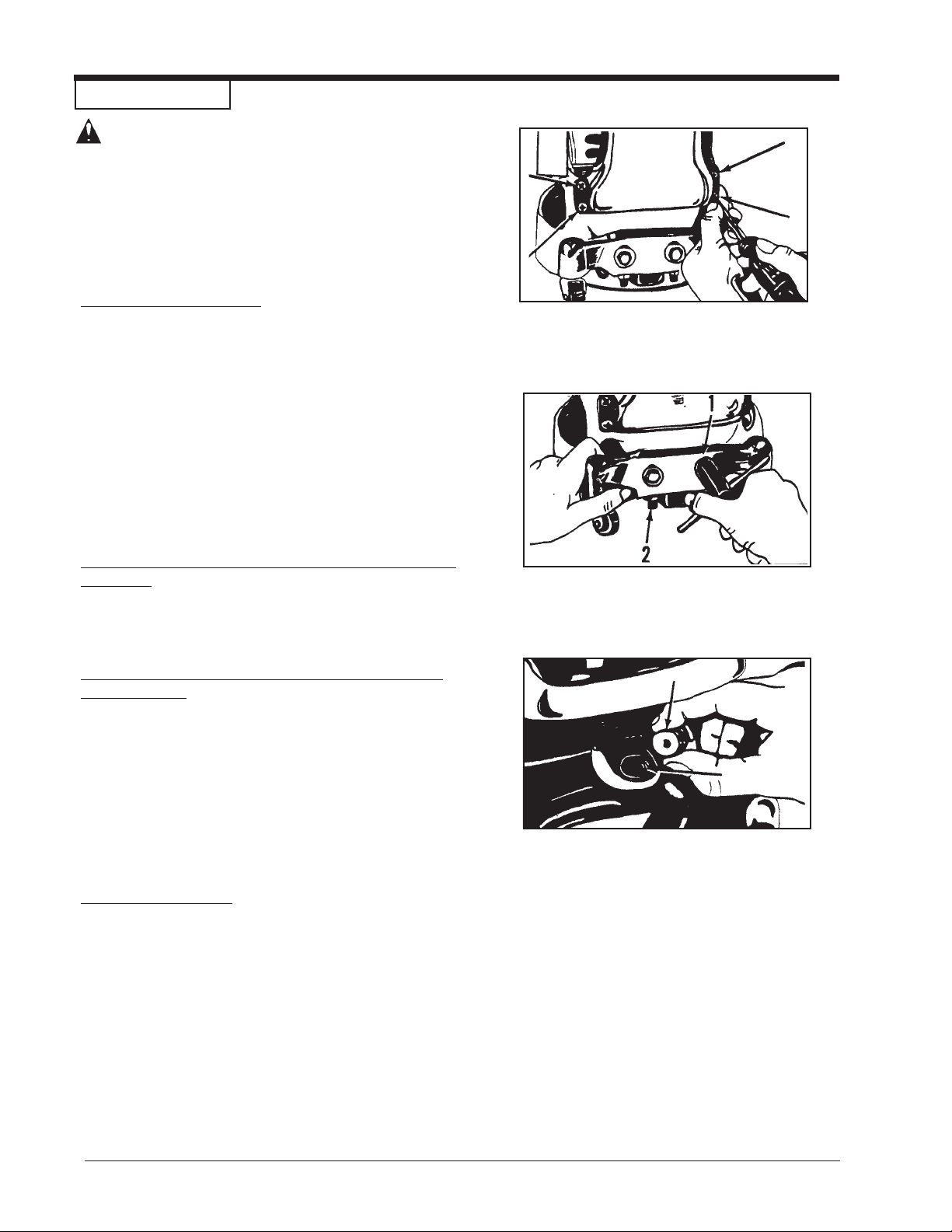
If the exhaust pipe gets an obstruction, follow this
procedure:
1. Remove the four screws that hold the exhaust pipe
to the housing. See figure 5.
2. Remove the obstruction from the exhaust pipe.
3. Install the exhaust pipe.
How to Adjust the Angle Of The Sandpaper Disc To
The Floor
The adjustment of the machine is correct when the front
part of the sandpaper disc makes contact with the floor.
To change the adjustment of the machine, follow
this procedure:
1. Using the special wrench, loosen the lock nut on
each caster. See (1) figure 6.1.
2. Loosen the jam nut. See (2) figure 6.2.
3. Raise or lower the casters as needed.
4. Tighten the jam nut on each caster.
5. Tighten the lock nut on each caster.
Figure 5
Figure 6
Figure 7
The Ventilation Plug
1. To clean the ventilation opening in the center of the
plug, remove the plug from the machine. With the
plug removed, also inspect the grease in the
gearbox. See figure 7.
- 10 - FORM NO. 70162B Clarke® American Sanders B-2 (CE) Operator's Manual
Page 12
MAINTENANCE
Lubricants
Lubrication
The machine is completely lubricated. The bearings and
gears in the gear unit have enough lubricant for approximately
six months of normal operation. All other bearings are sealed
and have enough lubricant for the life of the machine. No
lubricant is needed for the rotating disc guard.
How To Change The Lubricant In The Gearbox
To change the lubricant in the gearbox, follow this procedure:
1. Put the machine upside down on a bench.
2. Align one of the two holes in the rubber pad with one of
the three holes in the rotating disc guard.
3. Align both holes with one of the three screws in the
gear housing cover. Remove the screw from the gear
housing cover. See figure 9.
4. Align the holes with each of the other two screws, then
remove screws.
CAUTION: Make sure no dust enters the gear
box. Damage could occur to the gear
box.
Qty Part No.
1 Qt. 16610A
1 Gal. 166 1 1A
Figure 9
5. Remove the cover from the gear housing.
6. Remove the old lubricant from the gearbox.
7. Add ten ounces of Clarke American Sanders lubricant
to the gearbox.
CAUTION: To prevent damage to the motor,
do not add more than ten ounces
of lubricant to the gearbox.
8. Using the three screws removed above, install the cover
on the gear housing.
9. Start the machine and let it run for 15 minutes. A small
amount of excess lubricant should flow out the vent
hole. If none appears it may be necessary to add
additional lubricant.
10. Wipe off excess lubricant and clear vent hole.
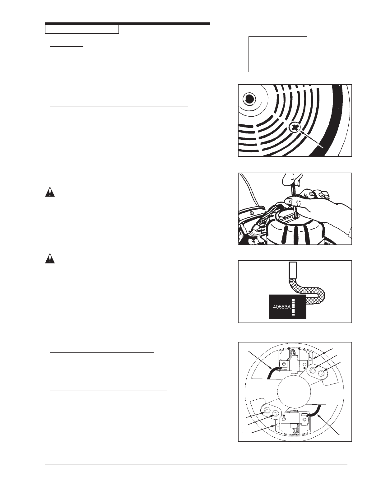
How To Check The Carbon Brushes
Depending on use, a set of brushes can be expected to last
250 hours and should be inspected sometime prior to that
time.
To check the brushes, follow this procedure:
1. Remove the motor cover. See figure 10.
2. Inspect the carbon brushes. Replace both brushes if
either brush has worn to 3/8" in length, or is worn to the
wear indicator. See figure 11.
3. To replace the brushes, disconnect the field wire (A)
from the brush holder (B). Then remove the two screws
and washers (C) securing the holder to the motor
housing. See figure 12.
Figure 10
Figure 11
A
B
C
C
C
C
B
Figure 12
A
®
Clarke
American Sanders B-2 (CE) Operator's Manual FORM NO. 70162B - 11 -
Page 13
MAINTENANCE
How To Check The Carbon Brushes (cont)
4. Gently pry the holder down from the motor
housing.
5. Rotate holder from beneath the motor housing and
lift out.
6. Disconnect the brush shunt wire from the holder.
For convenience, cut the terminal from the shunt
wire and remove brush.
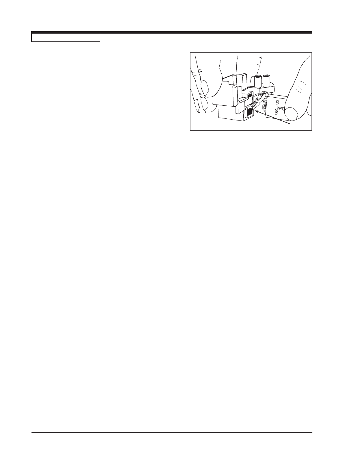
7. To put in a new carbon brush, negotiate the
terminal on the shunt wire by the spring and
brush holder guide. Take care not to damage the
spring. See figure 13.
8. Depress the brush into the guide and connec the
shunt wire to the holder.
9. Depress the brush and insert the holder into the
motor housing.
10. Rotate holder beneath motor housing. Relax
brush against commutator.
11. Align posts on holder with holes in housing.
12. Gently pry the holder into the housing.
13. Reattach screws and washers.
14. Start up the machine, if sparking between either
brush and the commutator occurs, use a brush
seating stone on the commutator to promote full
engagement between the brushes and commutator.
15. Install the motor cover.
Figure 13
- 12 - FORM NO. 70162B Clarke® American Sanders B-2 (CE) Operator's Manual
Page 14

B2B2
B2
B2B2
7" Spinner7" Spinner
7" Spinner
7" Spinner7" Spinner
Edger (CE)Edger (CE)
Edger (CE)
Edger (CE)Edger (CE)
Section II
Parts and Service Manual
(70162B)
®
Clarke
American Sanders B-2 (CE) Operator's Manual FORM NO. 70162B - 13 -
Page 15
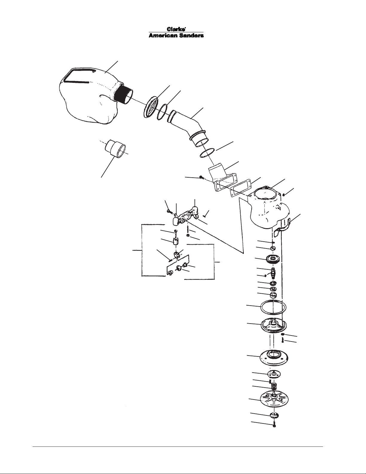
Model B-2 7" Spinner Edger (CE)
Drawing #1
1
2
3
4
3
5
44
42
38
17
18
12
13
6
7
8
9
11
14
10
19
15
16
39
19
40
41
20
21
22
23
24
25
26
27
28
29
30
31
32
33
43
34
35
36
37
- 14 - FORM NO. 70162B Clarke® American Sanders B-2 (CE) Operator's Manual
Page 16
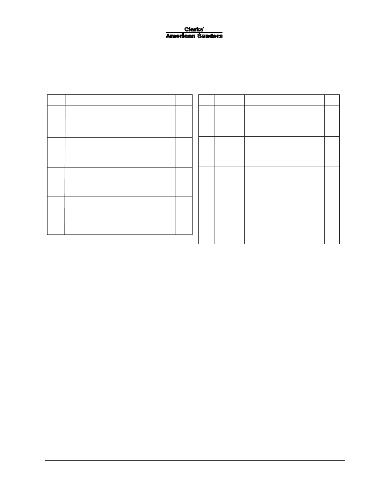
Model B-2 7" Spinner Edger (CE)
Parts List #1
Ref. Part No. Description Qty.
1 53544B Dust Bag 1
2 80276A Nut, Slip Joint 2" x 2" 1
3 3061 3A Washer, Seal 2
4 6171 2 A Tube, Exhaust 1
5 21078A Adaptor, Exhaust 1
6 962454 Screw - ¼ - 20 x 1 4
7 34233A Gasket 1
8 24509B Housing - Gear 1
9 66130A Plug 1
10 38103A Gasket 1
11 211 06A Barcket - Caster 1
12 858 1 4A Screw - 5/16 -18 x 1¼ Hx Hd 2
13 980676 Washer - 5/16 Fit 2
14 962170 Screw-Set 10-24 x ¼ 2
15 862 03A Screw - 5/16-18 x 1½ St 2
16 920160 Nut - 5/16-18 Hx Jam 2
17 857 01A Screw-¼-20 x 1½ Hx St 2
18 5112 8A Bearing 2
19 199 01A Yoke Assembly - Caster 2
20 467308 Ring - Retaining 1
21 5112 7A Bearing 1
Ref. Part No. Description Qty.
22 61568A Gear 1
23 67426A Shaft 1
24 915028 Key 1
25 57702A Ring - Retaining 1
26 58114A Seal - Oil 1
27 902550 Bearing 1
28 34232A Gasket 1
29 12906A Cover - Gearcase 1
30 59817A Washer - 1/4 Nylon Countersink 3
31 962098 Screw - ¼-20 x 3/4 Fit Hd 3
32 15000A Guard - Roller 1
33 66917A Retainer 1
34 39707A Washer - Felt 4
35 13200A Disc - Sanding 1
36 62411A Clamp - Paper 1
37 85715A Screw - 5/16-18 x 1 Hx Hd 1
38 925592 Pin ¼ x 1 Spirol 2
39 29404A Yoke, Edger Caster 2
40 50740A Bearing 4
41 299704 Roller Caster 2
42 12203A Caster Assembly 2
43 84200A Screw, 8-32 x ½ Flat Head 4
44 30563A Adaptor, 2" Tube x 1½" Hose 1
Note: Ref #19 (19901A) includes Ref. #'s17, 38, 39, 40 (2),
& 41
Note:Ref #42 (12203A) includes #'s 17, 18, 38, 39, 40 (2)
&41
®
Clarke
American Sanders B-2 (CE) Operator's Manual FORM NO. 70162B - 15 -
Page 17
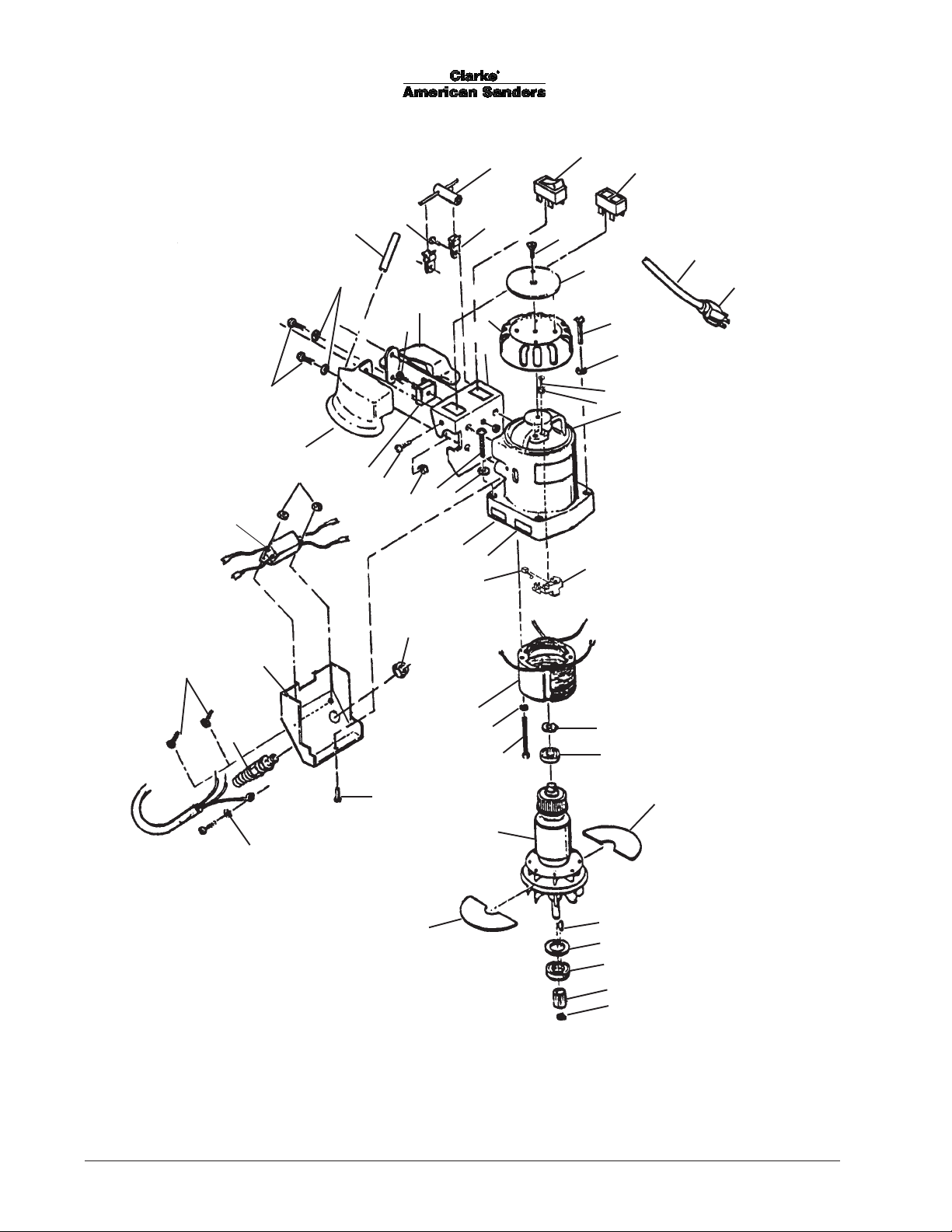
Model B-2 7" Spinner Edger (CE)
Drawing #2
3
5
6
45
48
50
47
51
49
10
1
52
44
2
54
53
43
55
4
7
11
56
57
8
9
10
12
14
15
13
9
10
42
41
17
16
46
21
44
25
34
33
32
31
23
24
25
26
27
28
29
30
- 16 - FORM NO. 70162B Clarke® American Sanders B-2 (CE) Operator's Manual
Page 18
revised 11/10
Model B-2 7" Spinner Edger (CE)
Parts List #2
Ref. Part No. Description Qty.
1 39305A Tubing 1
2 962823 Screw, 1/4-20 x 1/2 2
3 6870 5A Wrench - Special 1
4 6460 1A Holder - Wrench 2
5 47365A Switch Rocker 1
6 40114A Switch, Pushbutton 1
7 842 34A Screw - 5/16-24 x 3/8 Flt Hd 1
8 70686A Plate - Name 1
9 853 33A Screw - 1/4-20 x 2 Pn Hd 4
10 980657 Washer - 1/4 Lock 8
11 40115A Cord Set w/EU1-16P 1
4051 8A Cord Set w/UK1-13P 1
12 40073A Plug, 230V w/EU1-16P 1
45609A Plug UK1-13P 1
13 20011A Housing - Motor 1
14 962727 Screw, 8 - 32 x 1/2 4
15 980621 Washer 4
16 405 8 3 A Brush, Terminated 2
17 407 17A Holder, Brush 2
23 58602A Spring 1
24 5112 6A Bearing 1
25 60800A Baffle 2
26 65302A Key 1
27 58113A Seal 1
28 902550 Bearing 1
29 63701A Gear - Pinion 1
Ref. Part No. Description Qty.
30 57701A Ring - Retaining 1
31 10112A Armature - 230V 1
32 85358A Screw - 10-24 x 3½ Pn SS 2
33 980699 Washer - SH #1210 2
34 40719A Field Assembly - 240V 1
37 80200A Pin 2
38 980643 Washer - 7/16 OD x .036 Thk 2
39 67913A Spring 2
40 17407A Pin Assembly - Brush Spring Stop 2
41 215110 Label 1
42 215103 Label 1
43 81210A Nut Fixture
44 85520A Screw 8-00 x 1/2 3
45 962015 Screw, 10-24 x 3/8 2
46 56425A Strain Relief 1
47 50826A Cover 1
48 46739A Suppressor RF 240V 1
49 920296 Nut 10 -24 2
50 962454 Screw - 1/4-20 x 1 4
51 20012A Handle 1
52 912287 Diode Bridge 1
53 81217A Nut 1/4-20 2
54 962727 Screw, 8-32 x 1/2 2
55 24303A Handle - Left 1
56 62009A Cap - Motor Housing 1
57 50827A Enclosure 1
[ ] 30050A Case, Carrying 1
[ ] 56380639 Decal-Prop 65 1
[ ]# 56380216 Decal-Power Tool Warning 1
3/8 PT 2
[ ] = Not Shown
# = New or Revised Since Last Update
®
Clarke
American Sanders B-2 (CE) Operator's Manual FORM NO. 70162B - 17 -
Page 19
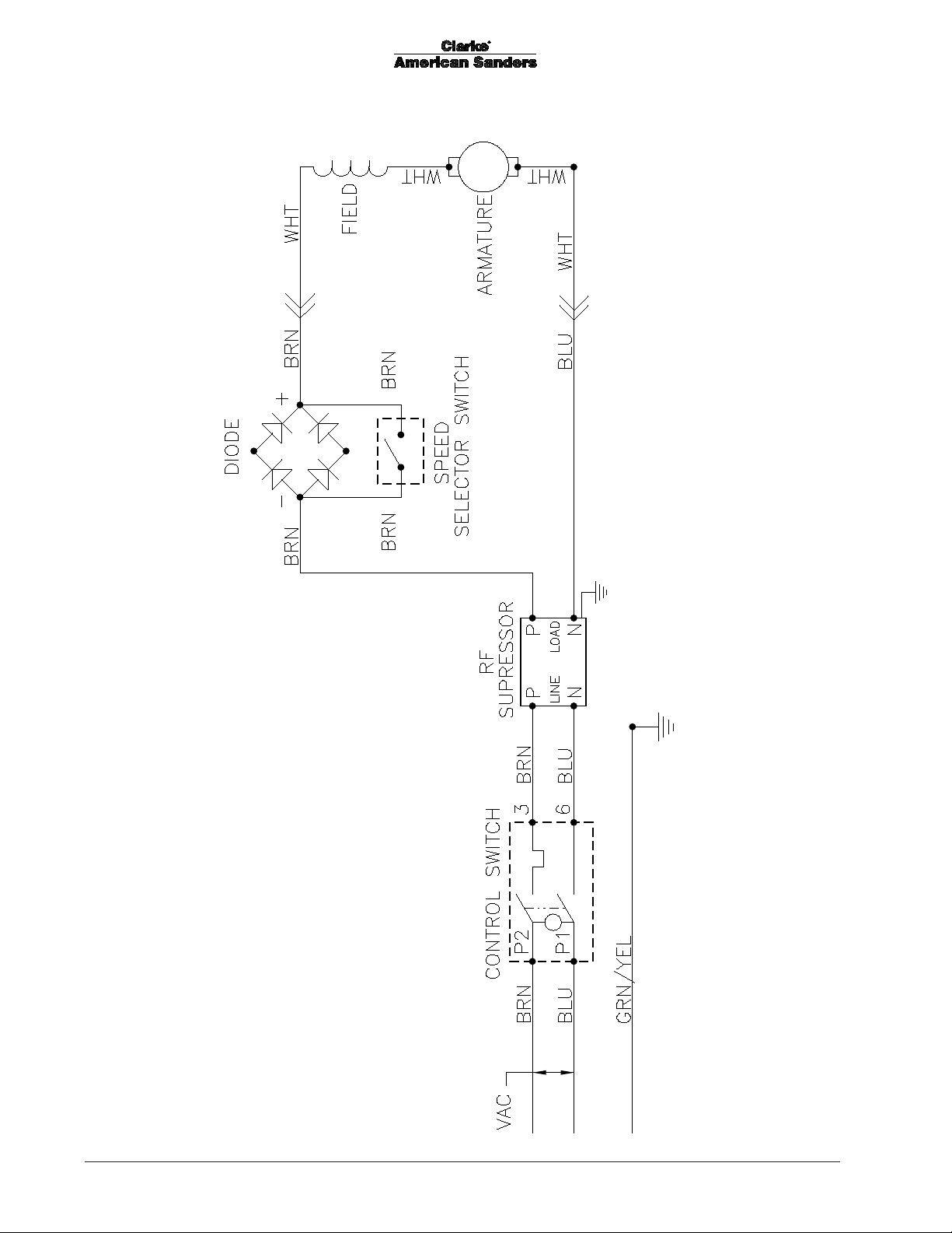
Model B-2 7" Spinner Edger (CE)
Wiring Diagram 11/99
- 18 - FORM NO. 70162B Clarke® American Sanders B-2 (CE) Operator's Manual
Page 20

Page 21

A Nilfi sk-Advance Brand
14600 21st Avenue North
Plymouth, MN 55447-3408
www.clarkeus.com
Phone: 800-253-0367
Fax: 800-825-2753
©2010 Nilfi sk-Advance, Inc.
 Loading...