

Page 1

Electronic Service
Manuals
This electronic document is provided as a service to our customers.
We do not create the contents of the information contained in this document. Should you have detailed questions pertaining to the information
contained in this document, you may contact Michco, or the manufacturer which provided the original information in this electronic deliverable. Michco’s only part in this electronic deliverable was the electronic
assembly process. By providing this manual on line we are not guaranteeing parts availability.
You may contact Michco through the following methods:
Phone (517) 484-9312 or (800) 331-3339
2011 N. High St. -- Lansing, Michigan -- 48906
Fax: (517) 484-9836
Email: [email protected]
Web site: www.Michco.Com
Parts Web site: www.FloorMachineParts.Com
Order Parts on Line at:
www.FloorMachineParts.Com
Directly to Parts & Service:
By Email: [email protected]
By Fax: (517) 702-2041
By Voice: Use numbers above.
Serving the Cleaning Industry Since 1922
Notice: All copyrighted material remains property of original owners, all trademarks are property of respective owners.
Manuals are subject to Manufacturer’s reproduction limitations. Originals or reproductions were provided by manufacturers
through a request. We make no warranty as to the correctness of information provided in this document and you assume
all risk. By placing these manuals on line we are not declaring our corporation to be an manufacturer authorized dealer or
provider, please check our web site for authorized manufacturers we represent.
Page 2
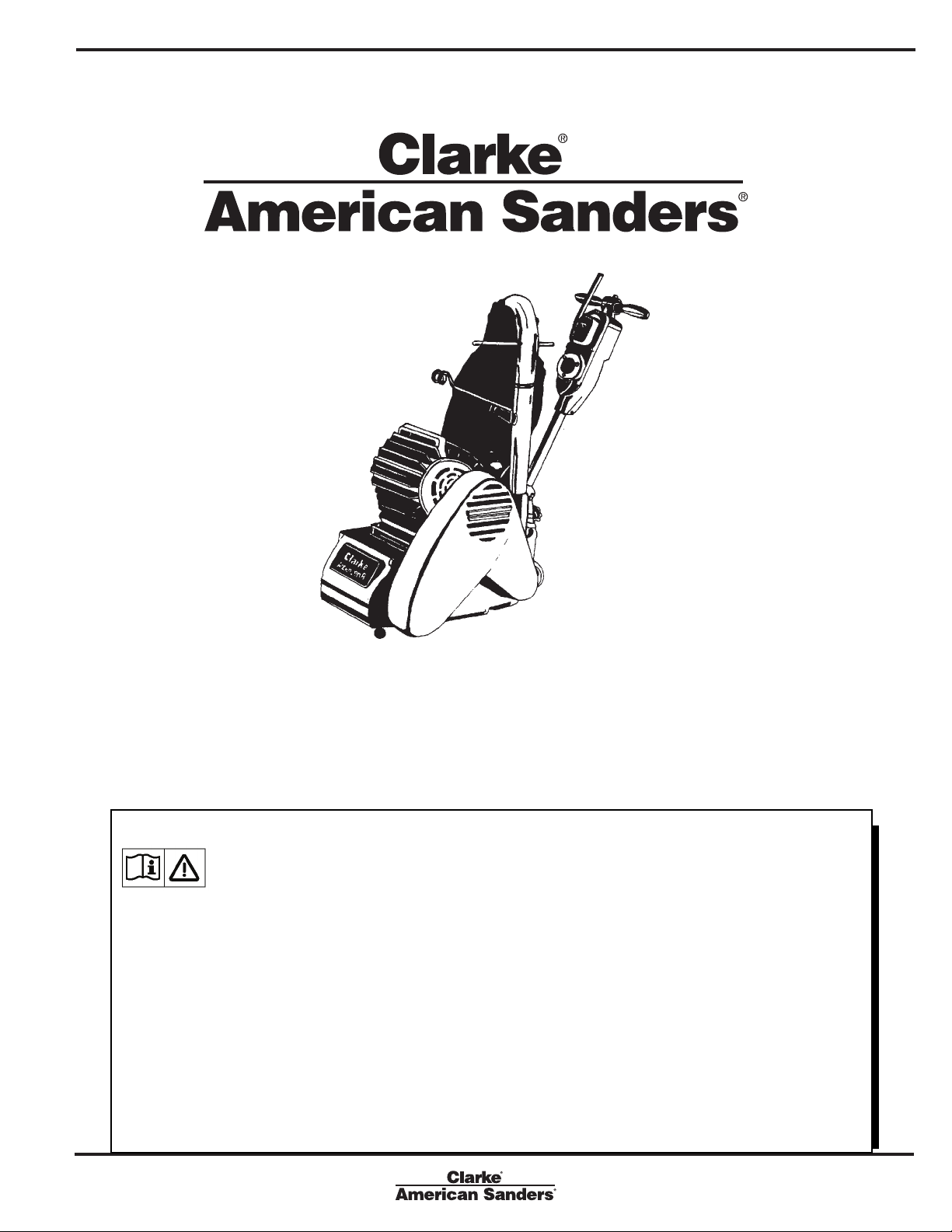
Operator’s Manual
American 8
Models: 07032C, 07105A, 07048C, 07106A
READ THIS BOOK
This book has important information for the use and safe operation of this machine. Failure to read this book prior to operating or attempting any service or maintenance procedure to your Clarke American Sanders machine could result in injury to
you or to other personnel; damage to the machine or to other property could occur as well. You must have training in the
operation of this machine before using it. If your operator cannot read this manual, have it explained fully before attempting
to operate this machine.
Si Ud. o sus operadores no pueden leer el Inglés, se hagan explicar este manual completamente antes de tratar el manejo
o servicio de esta máquina.
All directions given in this book are as seen from the operator’s position at the rear of the machine.
Form No. 78149D 5/03 revised 11/09
Page 3

Contents of this Book
Operator Safety Instructions ...............................................................................3
Introduction and Machine Specifi cations ............................................................ 5
230V Electrical Connection Instructions ............................................................. 6
How to Transport the Machine ............................................................................ 7
Machine Set-Up .................................................................................................. 8
How to Operate the Machine ............................................................................ 10
Sanding Cuts and Sandpaper ..........................................................................13
Sander Adjustment Procedures ........................................................................ 14
Routine Maintenance ........................................................................................ 16
Troubleshooting ................................................................................................ 17
Wiring Diagram ................................................................................................. 19
Assembly Drawing #1 ....................................................................................... 20
Assembly Parts List #1 ..................................................................................... 21
Assembly Drawing #2 ....................................................................................... 22
Assembly Parts List #2 ..................................................................................... 23
Assembly Drawing #3 ....................................................................................... 24
Assembly Parts List #3 ..................................................................................... 25
Accessories Drawing & Parts List ..................................................................... 26
Chatter-Wave Prevention ................................................................................. 27
WARNING: The Products sold with this Manual contain or may contain chemicals that are known to certain governments
(such as the State of California, as identifi ed in its Proposition 65 Regulatory Warning Law) to cause cancer, birth defects or
other reproductive harm. In certain locations (including the State of California) purchasers of these Products that place them in
service at an employment job site or a publicly accessable space are required by regulation to make certain notices, warnings or
disclosures regarding the chemicals that are or may be contained in the Products at or about such work sites. It is the purchaser’s responsibility to know the content of, and to comply with, any laws and regulations relating to the use of these Products in
such environments. The Manufacturer disclaims any responsibility to advise purchasers of any specifi c requirements that may
be applicable to the use of the Products in such environments.
Page 2 Form No. 78149D Clarke® American Sanders American 8 Floor Sander Operator's Manual
Page 4
OPERATOR SAFETY INSTRUCTIONS
WARNING AVERTISSEMENT ADVERTENCIA
DANGER means: Severe bodily injury or death can occur to you or other personnel if the DANGER statements
found on this machine or in this Owner’s Manual are ignored or are not adhered to. Read and
observe all DANGER statements found in this Owner’s Manual and on your machine.
WARNING means: Injury can occur to you or to other personnel if the WARNING statements found on your
machine or in this Owner’s Manual are ignored or are not adhered to. Read and observe all
WARNING statements found in this Owner’s Manual and on your machine.
CAUTION means: Damage can occur to the machine or to other property if the CAUTION statements found on
your machine or in this Owner’s Manual are ignored or are not adhered to. Read and observe
all CAUTION statements found in this Owner’s Manual and on your machine.
DANGER: Failure to read the Owner’s Manual prior to operating or attempting any service or maintenance procedure
to your Clarke American Sanders machine could result in injury to you or to other personnel; damage to the
machine or to other property could occur as well. You must have training in the operation of this machine before using it. If you cannot read English, have this manual explained fully before attempting to operate
this machine.
DANGER: Sanding/fi nishing wood fl oors can create an environment that can be explosive. The following safety proce-
dures must be adhered to:
• Cigarette lighters, pilot lights and any other source of ignition can create an explosion when active during
a sanding session. All sources of ignition should be extinguished or removed entirely if possible from the
work area.
• Work areas that are poorly ventilated can create an explosive environment when certain combustible
materials are in the atmosphere, i.e., solvents, thinners, alcohol, fuels, certain fi nishes, wood dust and
other combustible materials. Floor sanding machines can cause fl ammable material and vapors to burn.
Read the manufacturer’s label on all chemicals used to determine combustibility. Keep the work area well
ventilated.
• Spontaneous combustion or an explosion can occur when working with sanding dust. The sanding dust
can ignite and cause injury or damage. Sanding dust should be disposed of properly. Always empty the
sanding dust into a metal container that is located outside of any building(s).
• Remove the contents of the dust bag when the bag is 1/3 full. Remove the contents of the dust bag each
time you fi nish using the machine. Never leave a dust bag unattended with sanding dust in it.
• Do not empty the contents of the dust bag into a fi re.
• Hitting a nail while sanding can cause sparks and create an explosion or fi re. Always use a hammer and
punch to countersink all nails before sanding fl oors.
DANGER: Operating a machine that is not completely or fully assembled could result in injury or property damage. Do
not operate this machine until it is completely assembled. Keep
all fasteners tight. Keep adjustments according to machine specifi cations.
Clarke® American Sanders American 8 Floor Sander Operator's Manual Form No. 78149D Page 3
Page 5

DANGER: Electrocution could occur if the machine is used on a power circuit that repeatedly trips or is undersized. Have a
licensed electrician check the fuse, circuit breaker or power supply.
DANGER: Electrocution could occur if maintenance and repairs are performed on a unit that is not properly disconnected from
the power source. Disconnect the power supply before attempting any maintenance or service.
DANGER: Electrocution could occur if machine is used on ungrounded electrical circuit. Never remove or disable the grounding
supply conductor on the electrical cord. Consult an electrician if the grounding conductor is missing or if you suspect
your circuit is not grounded properly.
DANGER: Use of this machine with a damaged power cord could result in an electrical shock. Do not use the machine if the
power cord is damaged. Do not use the electrical cord to move the machine.
DANGER: Electrocution or injury could occur if the power cord is run over or damaged by the sander. Keep the cord free from
under the machine to avoid contact with the sandpaper. Always lift the power cord over the machine.
DANGER: Moving parts of this machine can cause serious injury and/or damage. Keep hands, feet and loose clothing away
from all moving parts of the sander.
DANGER: Operating a sander without all guards, doors or covers in place can cause an injury or damage. Always check to make
sure that all of the guards, doors and covers are secure and in place.
DANGER: Injury to the operator or bystanders could occur if the power supply remains connected when servicing the equipment,
changing abrasive, or empting the dust bag.
WARNING: Failure to read and observe all safety statements found on your machine or in this Owner’s Manual can result in seri-
ous injury or damage. Read and observe all safety statements. Make sure that all labels, decals, warnings, cautions,
and instructions are fastened to the machine. Get new labels from your authorized Clarke American Sanders distributor.
WARNING: Sanding dust can be airborne and can be breathed in while operating a sander. Always wear a dust mask while oper-
ating sanding equipment.
WARNING: Injury to the eyes and/or body can occur if protective clothing and/or equipment is not worn while sanding. Always
wear safety goggles, protective clothing, and a dust mask while performing any sanding operation.
WARNING: Bodily injury could occur if power is applied to the machine with the power switch already in the “ON” position. Always
check to assure that the power switch is in the “OFF” position before applying power to the power cable.
CAUTION: Maintenance and repairs performed by unauthorized personnel could result in damage or injury. Maintenance and
repairs performed by unauthorized personnel will void your warranty. Servicing of this unit must always be referred to
an authorized Clarke American Sanders distributor.
CAUTION: Use of this machine to move other objects or to climb on could result in injury or damage. Do not use this machine as
a step or furniture. Do not ride on this machine.
CAUTION: Damage could occur to the machine if not properly kept in a dry building for storage. Store the machine in a dry build-
ing.
CAUTION: The machine is heavy. When transporting the machine, remove the motor. Get help to lift the machine and motor.
CAUTION: Serious damage to the fl oor can occur if the machine is left running in one spot while the sanding drum is in contact
with the fl oor. To avoid damage to the fl oor, feather cut in at a normal sanding rate. Do not dwell while lowering or
raising the contact wheel. Always sand at a constant rate.
Page 4 Form No. 78149D Clarke® American Sanders American 8 Floor Sander Operator's Manual
Page 6
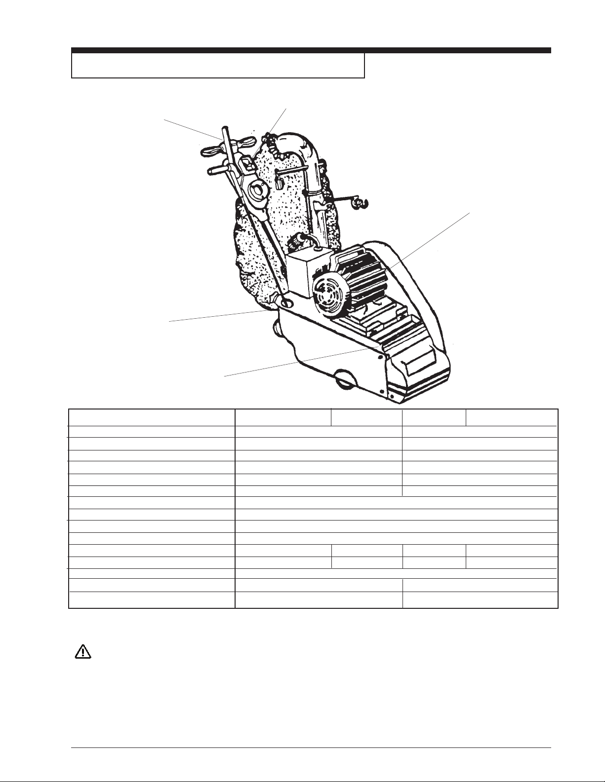
Introduction and Machine Specifi cations
Motor Starter / Protector
Operating Controls
Sanding Pressure
Adjustment
Leveling Controls
Tool Storage Tray
PART NUMBER
07032C 07105A 07048C 07106A
Abrasive Size 8 x 26½” paperback 20.3 x 67.3 cm
Contact Wheel Speed (rpm)* 2400/2800 2000/2333
Abrasive Speed (sfm)* (m/min)* 4398/5131 sfm 1117/1303 m/min.
Dust Fan Speed (rpm)* 6000 5000
Dust Fan Flow (cfm)* 210 cfm 83 liters/second
Motor 60 Hz 230V 4hp (3 kW) 50 Hz 240V 3hp (2.2 kW)
Leveling Control Externally Adjustable
Operating Control Adjustable Lever
Motor Starter/Protector Magnetic Circuit Breaker
Sanding Pressure Adjustment Infi nitely Adjustable
Wheels (Truck Assembly) Steel ** Urethane*** Steel** Urethane***
Wheel (Rear) Steel Canvas Steel Canvas
Drive V-Belt
Dimensions 40½ x 15 x 36 3/4 103 cm x 38 cm x 93 cm
Weight 216 lbs. 98kg
* revolutions per min. *surface feet per min. *meters per min * cubic feet per min.
**Steel (Standard) Urethane or canvas (optional) ***Urethane (Standard) Steel or Canvas (optional)
CAUTION: Your equipment may be inappropriate on some installations. Some softer woods used in fl ooring cannot
support the pressure created by hard wheels.
A felt or rubber wheel should be used when these woods are encountered.
See parts list for optional wheels.
Always consult with the fl ooring manufacturer on the proper installation, preparation, and fi nishing of their
product. Determine suitability of your equipment in preparing the product.
Clarke® American Sanders American 8 Floor Sander Operator's Manual Form No. 78149D Page 5
Page 7
230V Electrical Connection Instructions
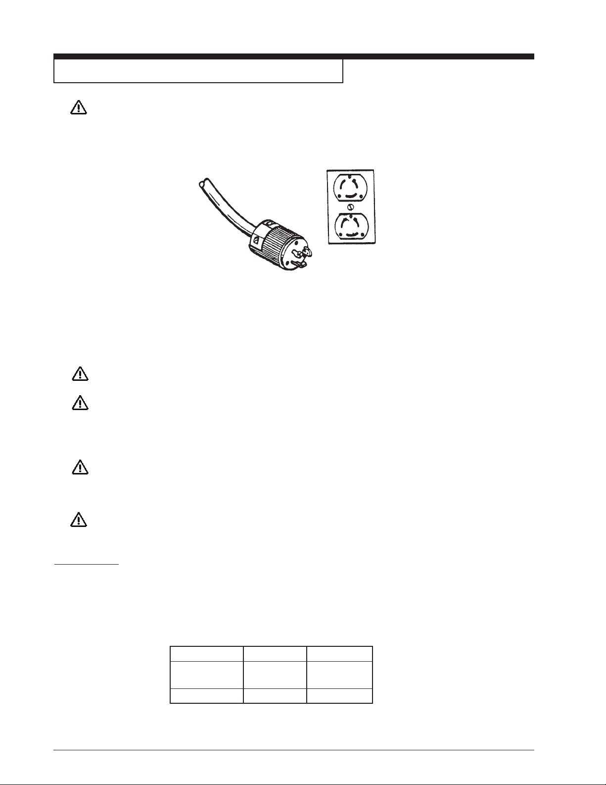
CAUTION: This machine will operate only on AC frequency and on electrical voltage shown on the motor nameplate.
Make sure you have the correct frequency and voltage before connecting the power cord to an outlet. The
machine has a plug as shown below.
This machine must be connected to an electrically ground circuit in order to protect the operator from electric shock. This machine has
an approved power cord with three conductors as well as a plug with three terminals. Connect the plug into a three holed receptacle.
For maximum protection against electric shock, use a circuit that is protected by a ground fault circuit interrupter.
DANGER: Electrocution could occur if the machine is exposed to water or rain. Keep the machine in a dry building.
DANGER: Electrocution could occur if machine is improperly connected to the electrical system. To prevent possible
electric shock, always use a 3 wire electrical system connected to an electrical ground. For maximum protection against electrical shock, use a circuit that is protected by a ground fault circuit interrupter. Consult
your electrical contractor.
DANGER: Electrocution could occur if the ground pin is tampered with in any way. Do not cut, remove, or break the
ground pin. Do not try to fi t a three-terminal plug into a receptacle or connector body other than a three
plug receptacle or connector body. If the outlet does not fi t the plug, consult your electrical contractor.
DANGER: Electrocution could occur if the machine is used with a damaged plug or power cord. If the cords or plugs
are worn or damaged in any way, have them replaced by an authorized service person or electrician.
Extension Cords
Use only an approved three-pronged extension cord with two main conductors and one earthing conductor. This machine’s power cord
has a wire size of 10 gauge. This machine is equipped with a 100’ power cord. When greater range is needed follow the table below
to determine cable guage of additional footage. Refer to the following chart for extension cord information.
Feet/Wire Guage (Stranded Copper)
Source Voltage 0-100’ 100-250’
208 6 Use Voltage
Booster
230 10 8
If motor appears to labor or takes a considerable longer time to come up to speed reduce sanding pressure.
Page 6 Form No. 78149D Clarke® American Sanders American 8 Floor Sander Operator's Manual
Page 8
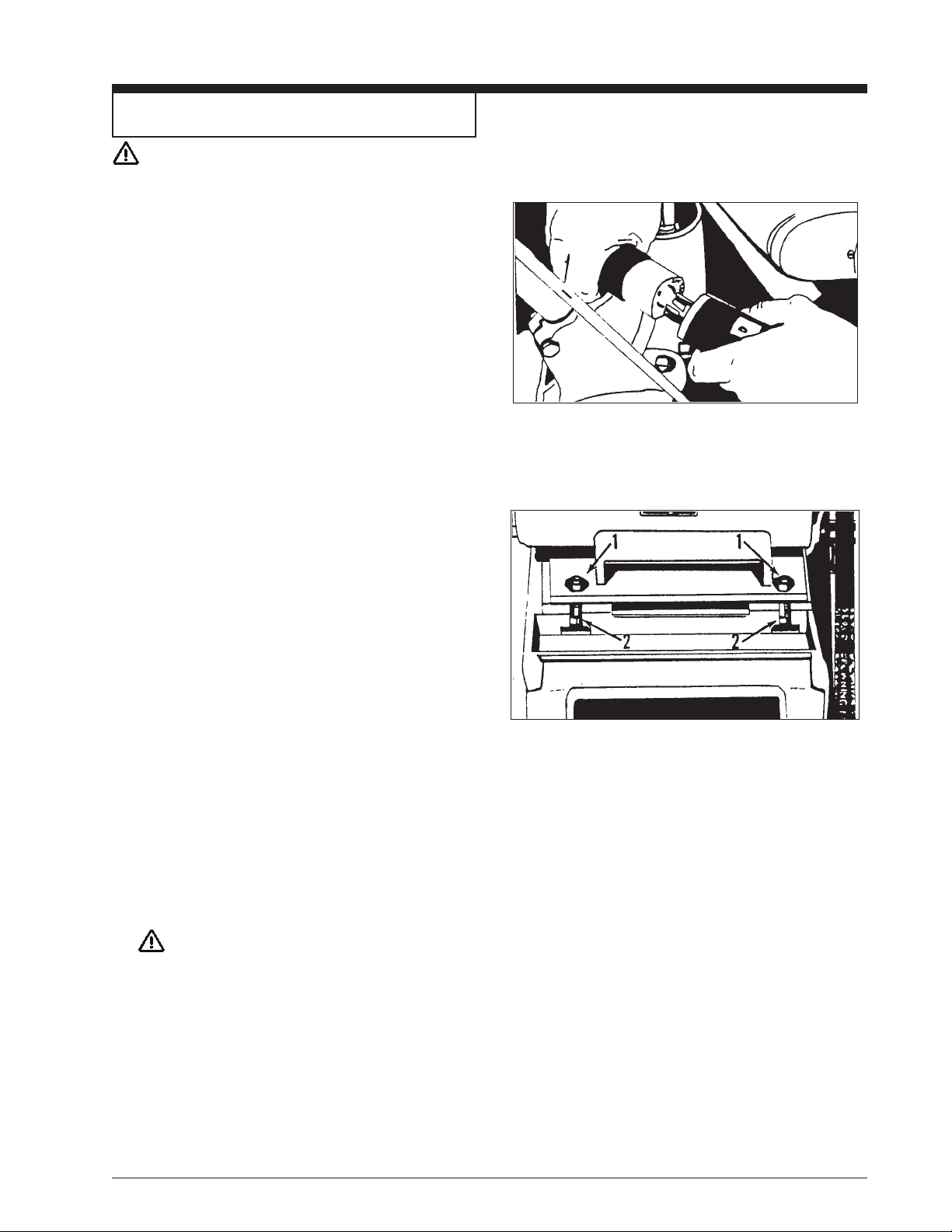
How to Transport the Machine
WARNING: The machine is heavy. Remove the
motor from the machine before transporting. Get help loading the machine
and motor.
To transport the machine, follow this procedure:
1. Make sure the power cable is disconnected from the
electrical outlet.
2. Disconnect the handle plug connection. See fi gure 1.
3. Remove the belt cover.
4. Remove the fan belt.
5. Loosen the motor bolt. Using the ¾” wrench, turn the motor
bolt counterclockwise.
6. Using the 9/16” wrench, remove the two hex
nuts (1).
Figure 1
7. Lower the motor locating screws (2). To lower the motor
locating screws, turn the screws clockwise. Make sure the
screws are aligned with the openings at the front of the
motor platform. See
fi gure 2.
8. Slide the motor forward.
9. Remove the drive belt.
10. Remove the motor from the chassis.
To re-assemble the machine after transporting, follow this
procedure:
1. Reposition motor on chassis.
2. Install the drum belt. Slide the motor back until adequate
tension is achieved in belt.
CAUTION: To prevent damage to the fl oor
surface, make sure the drive belt is
tight.
Figure 2
3. Resecure the motor to the chassis.
4. Install the fan belt.
5. Install the belt cover.
Reconnect the handle plug.6.
Clarke® American Sanders American 8 Floor Sander Operator's Manual Form No. 78149D Page 7
Page 9

Machine Set-Up
To set-up your machine follow this procedure:
1. Familiarize yourself with the machine and read all danger,
warning and caution statements. Make sure all operators
of this machine have read this Owner’s Manual. If they
cannot read English, have the manual explained fully before
allowing anyone to operate the sander.
2. Locate the power supply. The receptacle should be
compatible with the plug. The receptacle must be grounded
and must be fused (30 amp) to avoid an electrical hazard.
3. Clip the dust bag to the elbow. Cross the strings on the dust
bag and draw tight over the fl are on the elbow. Wrap the
string around the elbow and secure.
4. Wind the power cord through the cable arm. Keep the
power cord out of path of equipment.
How To Install The Abrasive
WARNING: Disconnect power before
changing abrasive.
To install the abrasive, follow this procedure:
1. Prepare abrasive with template supplied.
2. Place backing of abrasive on the template. The template is
marked “This Side Up.” Make sure the marked side of the
template is facing up.
3. Cut the abrasive to the exact lenght of the template.
4. Align one edge of the abrasive with a notch in the template.
5. Fold the other end of the abrasive over the end of the
template and crease.
6. Repeat steps 4 and 5 for remaining notch.
7. Lift the drum cover.
Page 8 Form No. 78149D Clarke® American Sanders American 8 Floor Sander Operator's Manual
Page 10
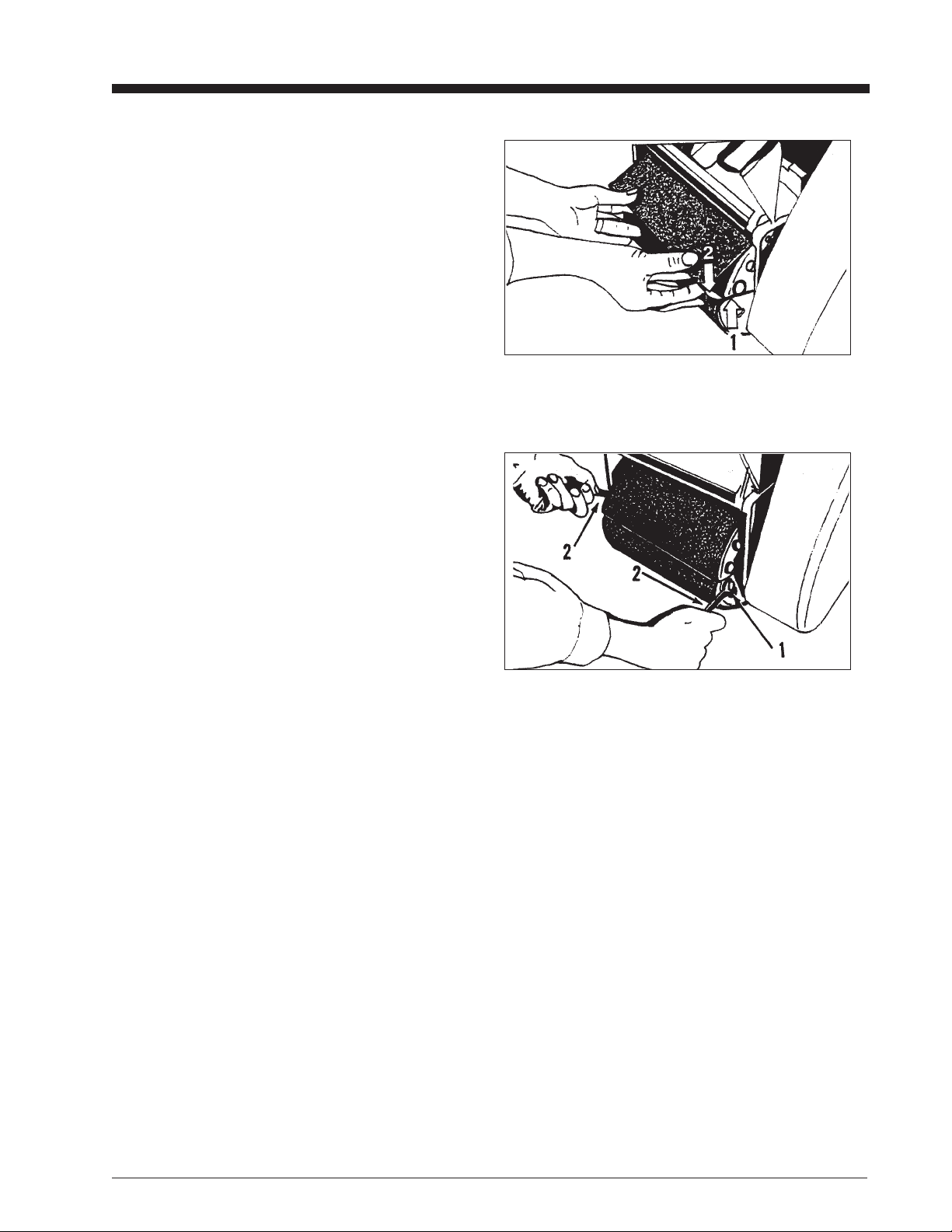
8. Put the smooth side of the abrasive against the sanding
drum.
9. Put one end of the abrasive against the sanding drum slot
(1). See fi gure 3.
10. Turn the drum one revolution. Put the other end of the
abrasive in the drum slot (2).
See fi gure 3.
11. Tighten the abrasive.
To tighten the abrasive, follow this procedure:
1. The end wrenches are given with the machine.
Put a wrench around the nut at each end of the
durm (1).
See fi gure 4.
2. Make sure the fl at sides of the nuts
are parallel with the drum slot.
3. Turn the wrenches the opposite rotation
until the abrasive is tight against the drum (2).
See fi gure 4.
12. Remove the end wrenches.
13. Close the cover.
NOTE: When using #4 or 4½ grit abrasive,
remove the large grains from the folded
ends. To remove the grains, rub the
folded ends together.
Figure 3
Figure 4
Clarke® American Sanders American 8 Floor Sander Operator's Manual Form No. 78149D Page 9
Page 11

How to Operate the Machine
DANGER: Sanding/fi nishing wood fl oors can create
an environment that can be explosive.
Cigarette lighters, pilot lights and any
other source of ignition can create an
explosion when active during a sanding
session. All sources of ignition should
be extinguished or removed entirely if
possible from the work area.
DANGER: Work areas that are poorly ventilated
can create an explosive environment
when certain combustible materials
are in the atmosphere, i.e., solvents,
thinners, alcohol, fuels, certain fi nishes,
wood dust and other combustible
materials. Floor sanding machines can
cause fl ammable material and vapors
to ignite. Read the manufac-turer’s
label on all chemicals used to determine
combustibility. Keep the work area well
ventilated.
DANGER: Sanding dust can spontaneously ignite
and cause an injury or damage. Sanding
dust should be disposed of properly.
Always empty the sanding dust into a
metal container. Remove the contents of
the dust bag when the bag is 1/3 full.
DANGER: Sanding dust can spontaneously ignite
and cause an injury or damage. Remove
the contents of the dust bag each time
you fi nish using the machine. Always
dispose of the dust in a metal container
located outside of the building. Never
leave a dust bag unattended with sanding
dust in it. Do not empty the contents of
the dust bag into a fi re.
DANGER: Hitting a nail while sanding can cause
sparks and create an explosion or fi re.
Always use a hammer and punch to
countersink all nails before sanding
fl oors.
Page 10 Form No. 78149D Clarke® American Sanders American 8 Floor Sander Operator's Manual
Page 12
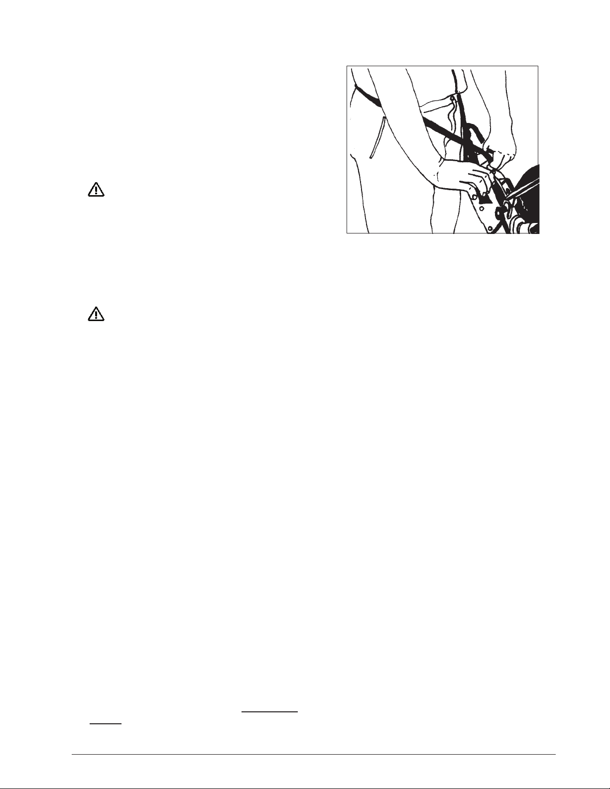
To operate the machine follow this procedure:
1. Install the operator’s belt as follows:
a. Position the operator’s belt around waist.
b. Cross the straps at the waist. See fi gure 5.
c. Slide the belt loop end over the handle on the control
lever side. Adjust the length as needed.
d. Wrap the remaining strap around the opposite side of
the handle and hold it in place with your hand.
WARNING: Should quick release of the machine
be necessary, serious operator injury
could occur if the operator has tied the
loose end of the operator’s belt strap to
the machine. Always position the strap
so that you can let go and get away
quick in case of bag fi re or explosion.
2. Put the On/Off switch into the “ON” position.
DANGER: Serious damage can occur to the fl oor
surface if the machine is not in motion
while the contact wheel is running on
the fl oor surface. To prevent damage to
the surface, make sure the machine is
always moving when the contact wheel
is in contact with the fl oor.
3. Work right to left. For each forward pass, move the
machine 4” over the pass you have just fi nished. Retrace
your reverse path without overlapping. See fi gure 6.
4. Feather-cut in by easing the contact wheel down onto the
surface with the control lever while the sander is in motion.
Figure 5
5. When contact wheel is fully engaged with the surface,
gradually adjust your pace for adequate fi nish removal.
Keep sander in motion while the contact wheel is engaged
with the surface or dwell marks will occur.
6. Move the machine in the direction of the grain in the wood
whenever it is possible. Sand the surface at a constant
pace.
7. Gradually feather-cut out at the termination point (the end of
your pass) by easing the contact wheel up with the control
lever. Stagger the termination points for a better blend
when edging.
8. Empty dust bag whenever it is 1/3 full. Never leave a dust
bag unattended with sanding dust in it. Sanding dust
can spontaneously ignite and cause a fi re or explosion.
Empty dust into a metal container located outside of the
building.
Clarke® American Sanders American 8 Floor Sander Operator's Manual Form No. 78149D Page 11
Page 13
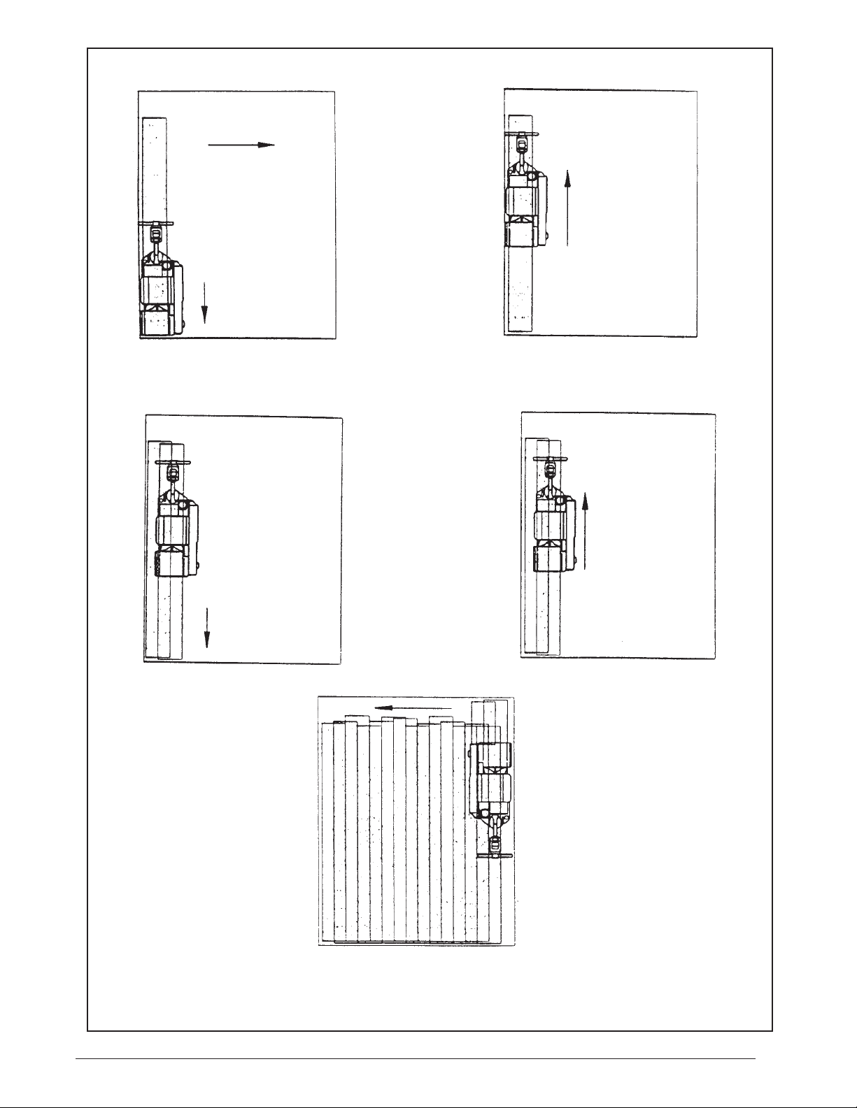
A. First pass forward, right to left.
B. First pass reverse, retrace same path.
C. Second pass forward, overlap ½ the
drum width.
E. Work the remaining unsanded fl oor
in the same fashion, right to left.
D. Second pass reverse, retrace
second path forward, etc...for the
entire room.
Figure 6
Page 12 Form No. 78149D Clarke® American Sanders American 8 Floor Sander Operator's Manual
Page 14

Sanding Cuts and Sandpaper
Initial Cut
The purpose of the initial cut is to remove old fi nish and gross imperfections on the fl oor surface. The sanding equipment should
be adjusted to heavy sanding pressure setting and a coarse abrasive should be used. If the surface is severely damaged by deep
scratches, pre-existing dwell marks, uneven planks, etc., it may be necessary to sand across or diagonally to the grain to restore
evenness to the surface. If these conditions are not present, the initial cut should be done in the direction of the grain.
If glazing, loading, or burning takes place immediately into an initial cut, select a coarser abrasive. If this should occur during an initial
cut, the abrasive has dulled and must be replaced.
Final Cuts
The purpose of a fi nishing cut is to remove the scratches produced during the initial cut. Use a fi ne (60 - 80 grit) grain abrasive and a
reduced sanding pressure setting.
If the surface remains rough after a fi nishing cut, it may be necessary to use an even fi ner grain of abrasive (80 - 100 grit). Care
should be taken in selecting the grit size of the abrasive. A very fi ne grain will close the pores on a wood fl oor making admission of a
stain diffi cult.
If glazing or burning should occur immediately into a fi nishing cut, reduce the sanding pressure. If it should occur during a fi nishing
cut, the abrasive has dulled and must be replaced.
Abrasive Bulk Roll
Note: All part numbers listed are for 8” x 50’ (203cm x 15m)
Grain Use Part No.
12 grit 945500
16 grit For removing gross imperfections and restore evenness 945501
20 grit to old fl ooring. To remove build-up of paints and varnishes. 945502
24 grit 945503
30 grit For fi rst sanding of new fl ooring (maple, oak). For removing 945504
36 grit minor imperfections and fi nishes from old fl ooring. 945505
40 grit For fi rst sanding of new fl ooring (oak, walnut). For removing 945506
minor imperfections and fi nishes from old fl ooring.
50 grit For fi rst sanding of new fl ooring (cedar, pine, fi r) 945507
For clean-up of 16 grit.
60 grit For clean-up from initial cut 36 - 40 grit. 945508
80 grit For fi nal sanding of certain hardwoods. For clean-up 945509
of initial cuts (50 grit).
100 grit For fi nal sanding of certain hardwoods where a smooth 945510
surface is desired.
120 grit For fi nal sanding of certain conifers. 945511
150 grit For fi nal sanding of certain conifers where a smooth 945512
surface is desired.
Clarke® American Sanders American 8 Floor Sander Operator's Manual Form No. 78149D Page 13
Page 15

Sander Adjustment Procedures
DANGER: Electrocution could occur if maintenance and
repairs are performed on a unit that is not
properly disconnected from the power source.
Disconnect the power supply before attempting
any maintenance or service.
DANGER: Moving parts of this machine can cause serious
injury and/or damage. Keep hands, feet and
loose clothing away from all moving parts of the
sander.
Sanding Pressure
To adjust the sanding pressure follow this procedure:
1. Screw the sanding pressure knob down to increase the sanding
pressure when making the roughing in cut.
2. Screw the sanding pressure knob up to decrease the sanding
pressure when making the fi nishing cut.
Drum Rates
The machine can be operated at two rates. To change the speed of
the drum, follow this procedure:
1. Remove the belt cover.
2. Remove the fan belt.
3. Loosen the motor bolt.
4. Remove the hex nuts at the front of the motor.
5. Using the 5/32” Allen wrench, lower the motor locating screws.
6. Slide the motor forward.
7. For high drum rates, install drive belt in larger diameter of the
grooves available on the motor pulley and in the smaller diameter
of the two grooves available on the drum pulley. For lower rates,
install drive belt in smaller diameter of the grooves available on
the motor pulley and in the larger diameter of the two grooves
available on the drum pulley.
8. Tighten belt and secure motor to chassis.
9. Install the fan belt.
10. Install the belt guard.
Page 14 Form No. 78149D Clarke® American Sanders American 8 Floor Sander Operator's Manual
Page 16
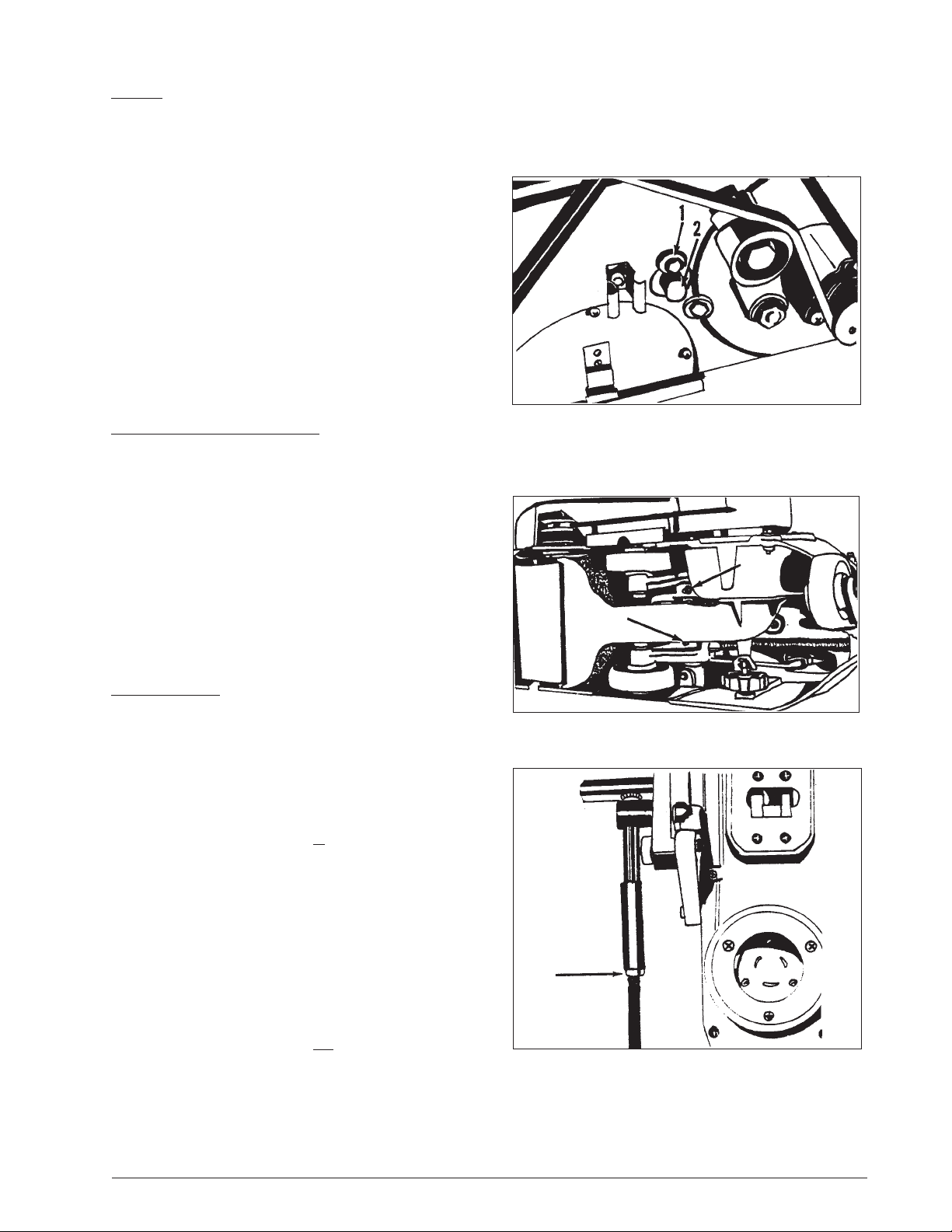
Leveling
If the sanding drum is out of adjustment, follow this
procedure:
1. Remove the belt cover.
2. Loosen the eccentric lock screw. Using the 7/16” wrench,
turn the eccentric lock screw (1) counterclockwise. See
fi gure 7.
3. To raise or lower the drum, turn the eccentric (2). See fi gure 7.
4. Tighten the eccentric lock screw. To tighten the eccentric lock
screw, turn the screw clockwise.
5. Install the belt cover.
How to Lubricate the Wheel Pivots
NOTE: The wheel pivots must be lubricated after every 25
hours of use.
To lubricate the wheel pivots, follow this procedure:
1. Put the machine on its side.
2. Lubricate the pivots. The pivots are behind the truck wheels.
See fi gure 8.
3. Put the machine on its wheels.
Operating Control
To increase the travel or extend the reach on the grip control
follow this procedure:
1. Loosen the locknut on the control rod.
See fi gure 9.
2. Screw the control rod adjuster in until the desired reach is
found.
Figure 7
Figure 8
3. Tighten the locknut.
To decrease the travel or reduce the reach on the grip control
follow this procedure:
1. Loosen the locknut on the control rod.
See fi gure 9.
2. Screw the control rod adjuster out until desired reach is
found.
Figure 9
3. Tighten the locknut.
Clarke® American Sanders American 8 Floor Sander Operator's Manual Form No. 78149D Page 15
Page 17

Routine Maintenance
The following items need to be periodically inspected and maintained to keep your sander in good working condition.
Wheels
Periodically remove the debris from the truck and caster wheels.
Debris can cause waves on a sanded surface. Lubricate truck
mechanism every 25 hours of use. The machine is equipped with
lubrication fi ttings and are located on shaft supporting mechanism.
Dust Bag
Remove the dust bag from the machine and shake it thoroughly
to remove the sanding dust from the dust bag. Turn the dust bag
inside out and machine wash in cold water to prevent pore blockage
and loss of dust recovery.
Drive Belt
Periodically check the drive belt tension.
Bearings
Periodically check the bearings for wear or damage according to the
following schedule:
Idler pulley after 1st 1500 hrs.
Fan shaft after 1st 2500 hrs.
Arbor shaft after 1st 5000 hrs.
Motor shaft after 1st 5000 hrs.
Page 16 Form No. 78149D Clarke® American Sanders American 8 Floor Sander Operator's Manual
Page 18

Troubleshooting
PROBLEM CAUSE ACTION
Drive belts slip. Insuffi cient tension. Tension drive belts
(Squeaking or squealing sound)
Worn belts. Replace belts.
Squealing, growling or grinding Damaged and/or worn bearing. Remove drive belts, rotate arbor
noise coming from machine. motor, fan, shafts and idler pulley to
locate dragging or rough bearing.
Contact an authorized dealer.
Dust pick-up is poor. Dust bag is over 1/3 full. Empty contents of bag.
Dust bag is dirty. Shake debris from bag and wash.
Dust chute is obstructed. Remove fan cover and clear throat.
Motor will not start. Defective motor starter. Contact an authorized dealer.
Defective start capacitor. Contact an authorized dealer.
Defective electronic start switch. Contact an authorized dealer.
Defective motor. Contact an authorized dealer.
No power. Check power supply and connections.
Motor runs sluggishly. Low voltage from excessive footage, Locate power source nearer to work site.
undersized extension cord, or poor Decrease sanding pressure.
connection.
Defective run capacitor. Contact an authorized dealer.
Defective motor. Contact an authorized dealer.
Motor starter trips/repeatedly Excessive load. Contact an authorized dealer.
trips. Defective electronic start switch. Contact an authorized dealer.
Defective motor starter. Contact an authorized dealer.
Low voltage from poor connection. Contact an authorized dealer.
Defective motor Contact an authorized dealer.
Defective capacitor. Contact an authorized dealer.
Uneven cut. Leveling out of adjustment. Readjust leveling.
Burning or glazing. Dull abrasive. Replace abrasive.
Excessive sanding pressure. Decrease sanding pressure setting.
Too fi ne of an abrasive. Use coarser abrasive.
Slow cutting. Dull abrasive. Replace abrasive.
Too fi ne of an abrasive. Use a coarser abrasive.
Insuffi cient sanding pressure. Increase sanding pressure setting.
Waves on sanded surface. Debris on wheel. Remove and clean wheels.
Flat spot on tire(s). Replace tires.
Chatter marks on sanded Drum out of round. Contact an authorized dealer.
surface (close evenly spaced ) or replace the drum.
Drum vibration. Change shim combination. Remove debris
from surface or ends of drum.
Clarke® American Sanders American 8 Floor Sander Operator's Manual Form No. 78149D Page 17
Page 19

NOTES
Page 18 Form No. 78149D Clarke® American Sanders American 8 Floor Sander Operator's Manual
Page 20
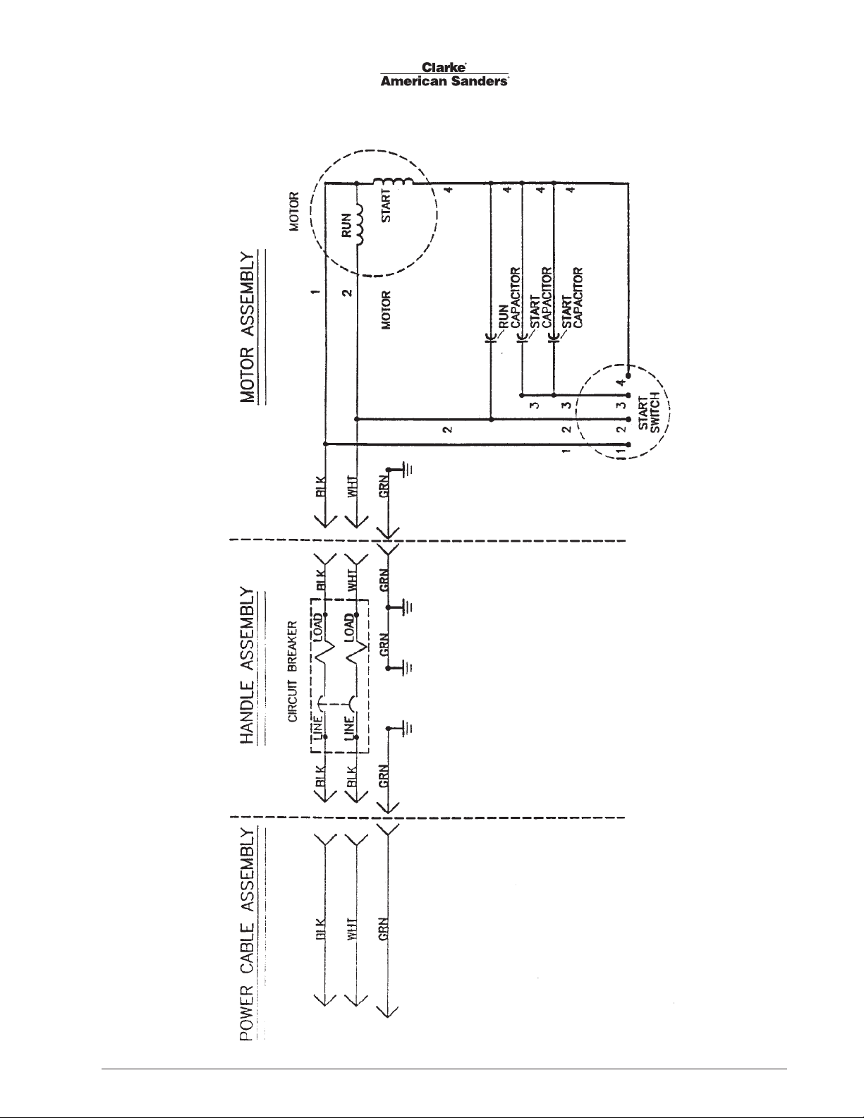
American Sander 8
Wiring Diagram 4/93
Clarke® American Sanders American 8 Floor Sander Operator's Manual Form No. 78149D Page 19
Page 21
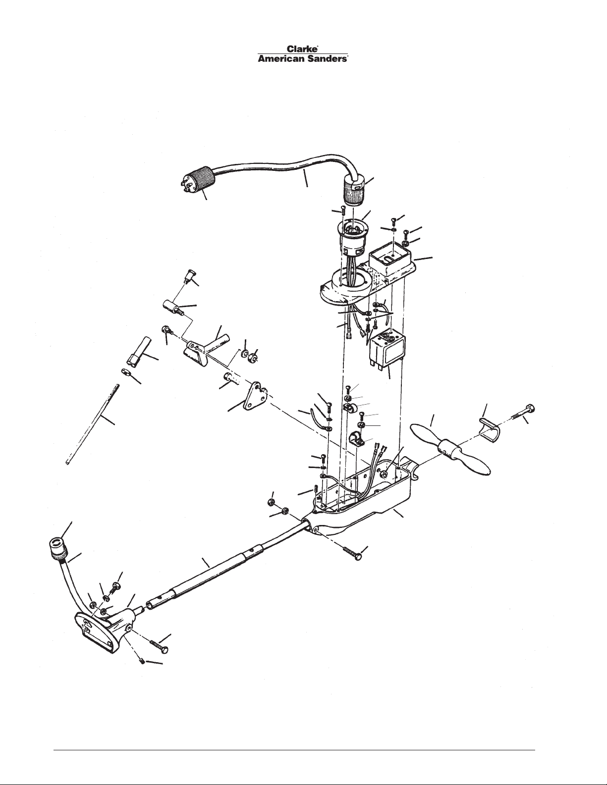
45
Model American 8 Floor Sander
Drawing #1 Handle Assembly 12/00
1
3
2
4
5
67
8
9
43
37
31
42
44
39
40
20
19
18
16
17
38
28
30
27
29
26
41
31
10
32
34
11
13
3
12
15
13
22
10
11
21
8
33
22
23
8
33
26
24
25
35
36
41
36
32
Page 20 Form No. 78149D Clarke® American Sanders American 8 Floor Sander Operator's Manual
Page 22

Model American 8 Floor Sander
Drawing #1 Handle Assembly 11/09
Ref No. Part No Description Qty
1 ref. Cord Set 1
2 41706A Connector 1
3 962065 Screw - 8-32 x ¼ Pn St Mach 4
4 43501A Inlet - 20A, 250V 1
5 962070 Screw - 6-32 x ¼ Pn St Mach 4
6 980607 Washer - #1106 Shakeproof 4
7 962794 Screw - 10-24 x 1 5
8 980650 Washer - 3/
9 22127C Cover - Switch Housing 1
10 48901A Wire Ass’y – Green 1
11 980699 Washer - #1210 Shakeproof 3
12 48900A Wire Assembly Ground 1
13 85393A Screw - 10-24 x ¼ Pn St Mach 3
Intentionally Omitted
15 49023A Wire Ass’y - Black 2
16 80021A Bolt 3/8 x 5/8 6
17 66151A Pivot Control Rod 1
18 80022A Bolt , Shoulder ½ x 5/8 1
19 67129A Adjuster, Control Rod 2
20 920148 Nut 3/8 - 16 1
21 41411A Switch - Circuit Breaker 1
22 85517A Screw - 10-24x½ 2
23 64405A Handle - Steering 1
24 21904C Clamp 1
25 85818A Screw 5/16 -18x 2½ Hex St 1
26 920284 Nut ¼-20 2
27 66694A Plate, Control Lever 1
28 85393A Screw ¼-2 x 1¼ 2
29 980646 Washer ¼ 1
30 25602A Lever, Control 1
31 920256 Nut - 5/16-18 Hex 3
32 86200A Screw 3/8 -16 x 5/8 St St Dogpt 2
33 51074A Clamp – Cord 2
34 980621 Washer - .1681 x .3700 SH 1108 1
35 20704C Housing – Switch 1
36 85816A Screw - 5/
37 41917A Cord – Interconnecting 1
38 66116C Pipe – Handle 1
39 962288 Screw - 3/8-16 X 1” Hex St Mach 3
40 21105C Mount – Handle 1
41 980652 Washer -.319 x .586 x .078 St Lk 2
42 980638 Washer - 3/8 Lt Spring Type 3
43 41707A Connector 1
44 67143A Rod Control 1
45 45608A Plug 1
[ ]# 56380639 Decal, Prop 65 1
Lock 7
16
-18x1¾ 2
16
# = Revised or new since last update
[ ] = Not Shown
Clarke® American Sanders American 8 Floor Sander Operator's Manual Form No. 78149D Page 21
Page 23
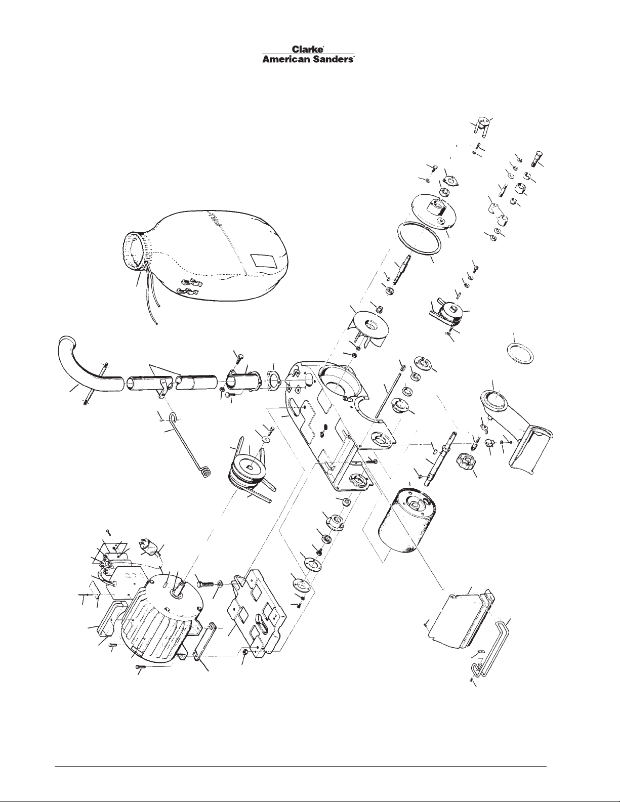
Model American 8 Floor Sander
Drawing #2 12/00
59
67
62
55
72
68
66
74
51
52
69
70
75
54
45
76
51
78
77
82
81
80
79
73
83
10
85
49
48
84
47
35
34
33
7
6
1
94
93
95
96
97
98
99
5
4
100
8
101
102
13
14 15
10
11
2
16
10312
104
17
18
21
22
26
25
24
23
28
29
30
31
37
36
27
41
24
38
71
11
25
56
39
46
58
57
56
45
51
42
91
92
90
89
88
53
87
Page 22 Form No. 78149D Clarke® American Sanders American 8 Floor Sander Operator's Manual
3
60
9
105
19 20
61
65
63
64
Page 24

Model American 8 Floor Sander
Drawing #2 12/00
Ref # Part No. Description Qty
1 62800A Pipe - Ass’y 1
2 85706A Screw - ½ - 13 x 1¾ Hex St 1
3 87006A Washer - .56 X 1.38 X .11 Flat 1
4 60401A Arm - Cable 1
5 925036 Pin - Cotter 1
6 66110A Pipe Ass’y 1
7 50954A Dust - Bag 1
8 44639A Motor 230/60 1
44640A Motor 240/50 1
9 920260 Nut - 3/8-16 x 5/16 Hex 2
10 50920A Belt - V 1
11 51024A Belt - V 1
12 66168A Pulley - Motor 1
13 920256 Nut
14 85820A Screw 15 85816A Screw - 5/16-18 x 1¾ Hex St Flt 1
16 27801C Support - Dust Pipe 1
17 34223A Gasket - Pipe Support 1
18 23405B Frame - Main 1
19 962016 Screw - 10-24 x ½ Pn St Mach 3
20 980650 Washer - 1941 x 3230 x 040 Lk 3
21 62608C Cover - Housing Drum 1
22 54305A Gasket 1
23 67316A Screw - Drum Lock 1
24 51110A Bearing - Ball 2
25 64703A Housing - Bearing Shaft 2
26 67811A Spacer - Drum 1
27 69032A Screw - Motor Locating 2
28 81202A Nut - 7/16-14 Hex L.H. 1
29 87002A Washer - .47 x .94 x .06 Flat St 1
30 23301A Fan 1
31 61602A Collar 1
Intentionally Omitted
33 902567 Bearing Ball 1
34 65302A Key - 1/8 x ½ #3 Woodruff 1
35 67411A Shaft - Fan 1
36 67414A Shaft - Drum Cover 1
37 67911A Spring 1
38 13501A Drum - RM 1
39 67425A Shaft Drum 1
NI 18601A Shaft Ass’y Drum (1)
includes 56, 39. 71
41 67313A Spacer - Drum Bearing 1
42 66918A Retainer - Bearing 1
Intentionally Omitted
Intentionally Omitted
45 962983 Screw - ¼-20 x 5/8 Pn St Mach 4
46 34225A Gasket - Plate Support 1
47 26503C Plate Support - Fan 1
48 51111A Bearing Ball 1
49 62001A Cap - Bearing 1
[ ] 38109A Seal Dust Pipe 1
51 980657 Washer - 17/64 I x 31/64 O x 1/16 7
[ ] = Not Shown
5
/16 - 18 Hex 1
3
/8-16 x 5/8 Hex St Cap 3
Ref # Part No. Description Qty
52 962823 Screw - ¼ - 20 x ½ Pn St Mach 3
53 77234A Label, Lifting Warning 1
54 66169A Pulley - Fan Shaft 1
55 66167A Pulley - Drum 1
56 80501A Key - 5/16 Sq. x 1.25 2
57 68703A Washer - Drum Pulley 1
58 980652 Washer - .319 x .586 x .078 1
59 962258 Screw - 5/16-18 x 1” Soc Cap 1
60 26107C Platform Motor 1
61 962262 Screw - 8-32 x ¼ St St Cup Pt 1
62 22101A Cover - Drum 1
63 62404A Clamp - Bumper Rear 1
64 962348 Screw - 10-24 x ½ Flat St Cap 1
65 31210A Bumper - Drum Cover 1
66 26900A Ring - Lock-Pan-Dust 1
67 67311A Screw 1
68 81900A Nut - 7/16 -14 Hex St 1
69 26100A Pan - Dust 1
70 61600A Clip - Dust 1
71 65301A Key #606 1
72 920280 Nut - 5/8 -18 x 3/8 Hex Jam 1
73 87102A Washer - .62 x 1.09 x .16 1
74 20400B Arm Idler 1
75 68000A Stud - Idler 1
76 87005A Washer - .52 x 1.00 x 1.00 1
77 87101A Washer - .50 X .12 Lock St 1
78 920132 Nut - ½-20 Hex Jam 1
79 67813A Spacer - Idler Bearing 1
80 67701A Sleeve - Idler 1
81 902550 Bearing 1
82 67317A Shaft - Idler 1
83 34222A Gasket - Pan Dust 1
84 980651 Washer-11/
85 85811A Screw - 3/8-18 x ¾ 3
x 11/
x 1/16 3
32
160
86 962103 Screw - 5/16-18 x 3/8 2
87 962216 Screw - 3/8-16 x ¼ 4
88 962870 Screw - 3/8-16 x 1 1
89 64460A Handle Motor 1
90 32357A Cover Handle 2
91 930087 Rivet 2
92 74044A Plate Safety 1
93 697502 Strain Relief 1
94 41305A Capacitor Start 2
95 41304A Capacitor Run 1
96 47378A Switch Start 1
97 962823 Screw - ¼-20 x ½ 2
98 980614 Washer 2
99 45604A Plug Locking 1
100 41945A Cord Motor 1
101 915098 Key ¼-52 x 1½ 1
102 57712A Ring Retaining 1
103 87034A Retainer Pulley 1
104 962288 Screw 3/8-16 x 1 1
105 67642A Shim, Motor 4
Part # Description Qty.
50563A End Bell 1
52768A Front Cover 1
53998A Fan 1
Motor Parts Not Illustrated
Part # Description Qty.
51188A Bearing Front 1
902547 Bearing Rear 1
40316A Armature Assembly 1
52769A Fan Cover 1
Clarke® American Sanders American 8 Floor Sander Operator's Manual Form No. 78149D Page 23
Page 25
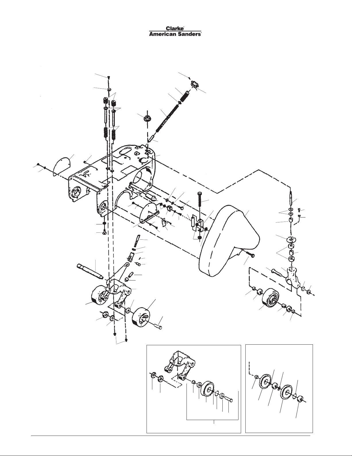
American 8 Floor Sander
Assembly Drawing #3 5/03
14
15
13
64
4
59
43
63
1
44
51
41
2
64
8
11
16
14
30
12
40
31
5
7
17
18
19
24
26
32
34
33
38
68
3
62
21
37
41
25
26
63
60
42
67
62
20
54
64
40
22
23
35
36
39
65
54
6
9
66
10
27
28
15
29
45
46
47
48
49
11
50
52
22
58
63
41
Page 24 Form No. 78149D Clarke® American Sanders American 8 Floor Sander Operator's Manual
60
Optional
Urethane Wheels
54
57
56
55
54
53
64
Urethane Caster Wheels
62
69
Optional
72
70
22
71
69
70
Page 26

American 8 Floor Sander
Assembly Drawing #3 5/03
Ref. No Part No. Description 07032C 07105A
07048C 07106A
Qty Qty
1 962052 Screw - 10-24 x ½ Flt St Mach 1 1
2 962161 Screw - 10-24 x 3/8 St St Cuppt 2 2
3 25200C Knob - Hand 1 1
4 66912A Retainer, Screw Adjusting 1 1
5 67309A Screw 1 1
6 67312A Screw 2 2
7 87000A Washer 1 1
8 67905A Spring 1 1
9 66123A Plunger, Spring 2 2
10 67906A Spring 2 2
11 67107A Rod - Pivot 1 1
12 23405B Frame, Main 1 1
13 66628C Plate, Cover Wheel 1 1
14 962015 Screw, 10-24 x 3/8 Pn St Mach 6 6
15 980650 Washer, Lock 6 6
16 62801A Eccentric 1 1
17 87007A Washer, Control Shaft Eccentric 1 1
18 980614 Washer, #1114 Shakeproof 1 1
19 85700A Screw, ¼-20 x 1” Hex 1 1
20 70224B Kit Guard, Belt 1 1
21 60715B Bolt, Pivot 1 1
22 87003A Washer, .59 x 1.00 x .09 Flat 4 3
23 67812A Spacer, Bracket 1 1
24 51069A Tube, Latch 1 1
25 962823 Screw, ¼-20 x ½ Pn St Mach 3 3
26 980657 Washer,
27 920112 Nut, #6-32 Hex 2 2
28 980607 Washer, #1106 Shakeproof 2 2
29 66627A Cover, Truck Wheel 1 1
30 87004A Washer, Fit St 2 2
31 61600A Clip, Dust 1 1
32 962983 Screw, ¼-20 x 5/8 Pn St Mach 1 1
33 63904A Clamp, Belt Guard 1 1
34 85313C Screw, 6-32 x
35 66913A Retainer, Bearing 1 1
36 51112A Bearing, Ball 2 2
17
/64 I x 31/64 O x 1/16 4 4
3
/8 Pn St Mach 2 2
Ref. No Part No. Description 07032C 07105A
07048C 07106A
Qty Qty
37 67821A Spacer 1 1
38 81102A Nut, ¼-20 ESNA 2 2
39 29403C Yoke, Wheel 1 1
40 60101A Axle 3 1
41 87101A Washer 3 3
42 51071A Bracket, Latch 1 1
43 920160 Nut
44 86201A Screw
45 67143A Rod, Control 1 1
46 920260 Nut
47 53917B Clevis,Control Rod 1 1
48 925036 Pin, Cotter
49 66503A Pin, Fork 1 1
50 62000A Nut, End 1 1
51 67412A Shaft, Control 1 1
52 21101A Bracket, Truck Wheel 1 1
53 60547A Axle - 2
54 51225A Bearing, Ball 6 6
55 167312 Ring, Retainer - 2
56 60481A Spacer - 2
57 50992A Wheel, Asm. - 2
58 54000A Fitting, Lub 2 2
59 57101A Plug, Soft 1 1
60 60544A Spacer 2 2
62 67810A Spacer 2 2
63 920196 Nut, ½ - 13 3 3
64 59928A Wheel (Steel) 3 [ ] 10243A KIt, Wheel (Urethane)(Optional) - 65 67817A Spacer 1 66 81209A Nut, ½-13 Flange 1 1
67 85806A Screw, ¼-20 x ¾ 1 1
68 87007A Washer, ¼- ¾ x .06 1 1
69 61333A Wheel, Caster 4” - 2
70 51226A Bearing - 4
71 747304 Ring, Retaining - 2
72 61355A Spacer - 2
5
/16 -18 1 1
5
/16 -18 x 1” 1 1
3
/8 -16 x 5/16 1 1
3
/32 x ¾ 1 1
[ ] = Not Shown
Clarke® American Sanders American 8 Floor Sander Operator's Manual Form No. 78149D Page 25
Page 27
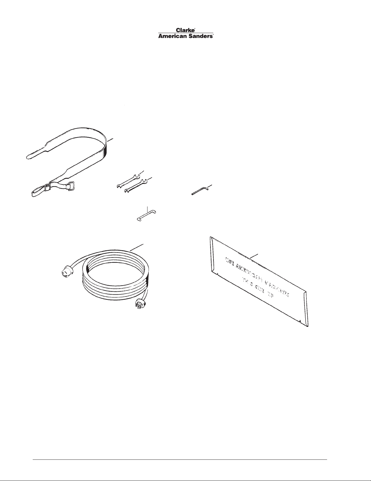
American 8 Floor Sander
Accessories Drawing & Parts List #4 12/00
1
2
1
5
2
3
4
5
6
Ref. # Part No. Description Qty
1 60724A Belt, Operating 1
2 59811A Wrench, End ¾ x 7/16 1
3 59810A Wrench, End 9/16 x 7/16 2
4 59815A Wrench 5/32 1
5 64415A Handle, Carrying 1
6 42201A Cord Set 230V 60Hz 1
40010A Cable Australia 1
7 68315A Template 1
7
Page 26 Form No. 78149D Clarke® American Sanders American 8 Floor Sander Operator's Manual
Page 28
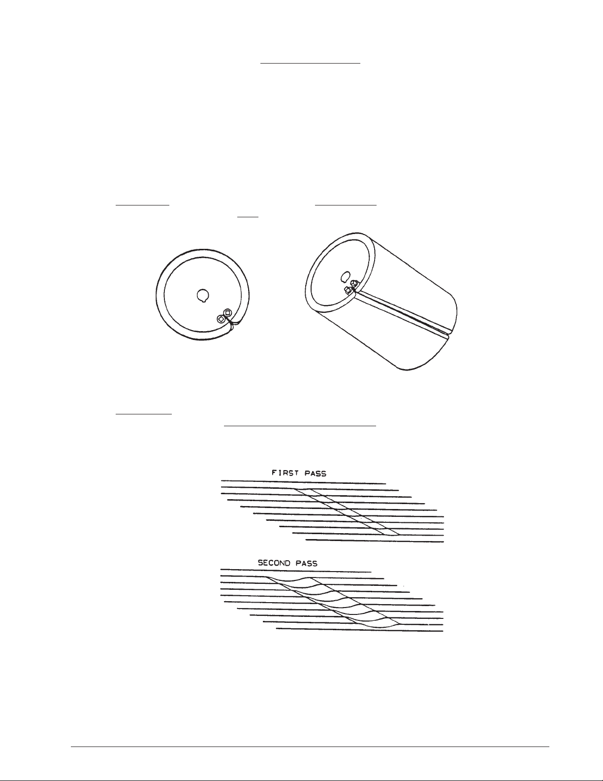
Chatter - Wave Prevention
Clarke American Sanders are designed and manufactured to the most rigid tolerances. However, after a fi nishing cut it is possible to
see “chatter” or “waves”.
The best guarantee to remove the chatter is to fi nish the fl oor with a
rotating horizontal sander, such as Clarke American Sanders’s Sander 16.
To minimize chatter when using a belt or drum sander the following steps should be taken:
1) DRUM PAPER...insure the paper is secured in the slot, but not too tight. Paper that
is too tight will force the drum slot wider, leaving a “slot mark chatter” on the fl oor.
2) DRUM MARKS........are caused by the operator lowering the drum to the fl oor without forward traverse. These marks
should be removed by cutting at a 45 degree angle to the mark. Cutting
at the mark while maintaining the same path will only increase the mark depth and width.
Clarke® American Sanders American 8 Floor Sander Operator's Manual Form No. 78149D Page 27
Page 29

Chatter Wave Prevention (cont)
3) UNEVEN WALKING PACE..... can leave lengthy “waves”. The machine cuts more material during the slower pace.
Pay particular attention to a steady, even pace.
4) EXCESSIVE LIGHT CUTS.... may reveal high spots on the paper/contact wheel and cause chatter. Take a heavier cut
and increase the pace.
5) DEBRIS.... lodged between the paper and the drum will leave chatter. On a belt sander, debris may be adhered to the
drum. Insure the drum is clean and free of debris before placing the paper on.
6) SANDER PAPER QUALITY....may vary. Belt seams can be thicker on low quality paper and cause chatter. Use only
Clarke American Sanders specifi ed sandpaper.
PROPER CARE OF YOUR MACHINE CAN MINIMIZE CHATTER AND WAVES.
1) V-BELTS.... can cause vibration and chatter if they are of low quality. Use only belts specifi ed by Clarke American Sand-
ers.
2) TRUCK AND CASTER WHEELS....with fl at spots, out-of-roundness, or debris adhered to their surface can cause
“waves” or a “chatter effect”. Always clean and inspect all wheels before starting to sand, and before the fi nish
cut. Replace or true the wheels if found to be out-of-round.
3) DUST PICK-UP SHOES.......may need adjusted differently for different materials that are to be sanded. An improperly
adjusted shoe will leave trailing debris that will be run over by the wheels and cause “random waves”.
4) CONTACT WHEELS (DRUMS).......may be out-of-round and cause “chatter”. Contact your Clarke American Sanders
dealer for assistance to true or replace the drum.
5) BEARINGS......in the motor, drum, or fan system may become worn and induce vibration which could cause “chatter”.
6) PULLEYS.....that are damaged or severly worn can induce vibration and cause “chatter”. Contact your Clarke American
Sanders dealer for assistance.
Clarke American Sanders is not responsibile for rework of fl oors that are unacceptable to the customer. It is your
responsibility to insure your equipment is in proper operating order, and that you use the right machine for the job.
Page 28 Form No. 78149D Clarke® American Sanders American 8 Floor Sander Operator's Manual
Page 30

Page 31

Page 32

Page 33

A Nilfi sk-Advance Brand
14600 21st
Plymouth, MN 55447-3408
www.clarkeus.com
Phone: 800-253-0367
Fax: 800-825-2753
©2010 Nilfi sk-Advance, Inc.
Avenue North
 Loading...