

Clark SM-619, G127, GP127, Gl27E, GPl27E Service Manual
...
SM-619
G127, GP127
Gl27E, GPl27E
CUIRK
CONTENTS
SERVICE MANUAL
SM619
GCSl2-15-17s
GCXl2-15E
GPSl2-15-17
GPXl5-17E
CONTENTS
GROUP
PAGE
FOREWORD
HOW TO USE THIS MANUAL
SAFETY SIGNS AND SAFETY MESSAGES
USER SAFE MAINTENANCE PRACTICES
PICTORIAL INDEX
PLANNED MAINTENANCE INTERVALS
SAFETY AND OPERATIONAL CHECKS
RECOMMENDED PLANNED MAINTENANCE AND
LUBRICATION SCHEDULE
PM
00
00
00
01
01
02
02
06
11
12
12
22
22
23
25
26
29
30
32
34
38
38
40
40
40
Planned Maintenance Program
4G32 Engine - 1.6 Liter
4652 Engine - 2.0 Liter
4663 Engine - 2.0 Liter
Cooling System - Troubleshooting
Cooling System
Fuel System - Gas
Fuel System - LPG
Transaxle (Transmission)
Electrical - Distributor
Electrical - Alternator
Electrical - Starter
Wheels and Tires - Cushion
Wheels and Tires - Pneumatic
Hydraulic Brakes & Inching
Steering Gear
Power Steering System - Steer Axle
Hydraulic System, Main Pump
Main Hydraulic Valve
Tilt Cylinder
Upright
Counterweight
Machine Jacking & Blocking
Truck Data Plate and Decals
Specifications
Hydraulic and Electrical Diagrams
ii
ii
III
iv
vi
vi
vii
. . .
VIII
PM-l
00-l -1
00-2-l
00-3-l
01-1-l
01-2-l
02-l -1
02-2-l
06-l -1
11-1-l
12-1-1
12-2-l
22-l -1
22-2-l
23-l -1
25-1-l
26-l -1
29-l -1
30-l -1
32-l -1
34-l -1
38-l -1
38-2-l
40-l -1
40-2-l
40-3-l
Index - Provides help for locating information about various topics.
SM 619, Jan ‘98
Contents-l
Grow PS, Periodic Service
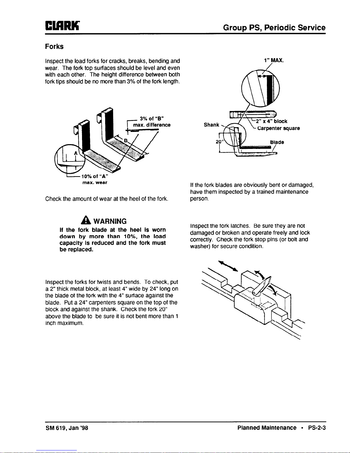
Forks
inspect the load forks for cracks, breaks, bending and
wear. The fork top surfaces should be level and even
with each other. The height difference between both
fork tips should be no more than 3% of the fork length.
max. wear
Check the amount of wear at the heel of the fork.
1" MAX.
If the fork blades are obviously bent or damaged,
have them inspected by a trained maintenance
person.
A
WARNING
If the fork blade at the heel is worn
down by more than lo%, the load
capacity Is reduced and the fork must
be replaced.
Inspect the fork latches. Be sure they are not
damaged or broken and operate freely and lock
correctly. Check the fork stop pins (or bolt and
washer) for secure condition.
Inspect the forks for twists and bends. To check, put
a 2” thick metal block, at least 4” wide by 24” long on
the blade of the fork with the 4” surface against the
blade. Put a 24” carpenters square on the top of the
block and against the shank. Check the fork 20”
above the blade to be sure it is not bent more than 1
inch maximum.
SM 619, Jan ‘98
Planned Maintenance l PS-2-3
Group 00, Engine
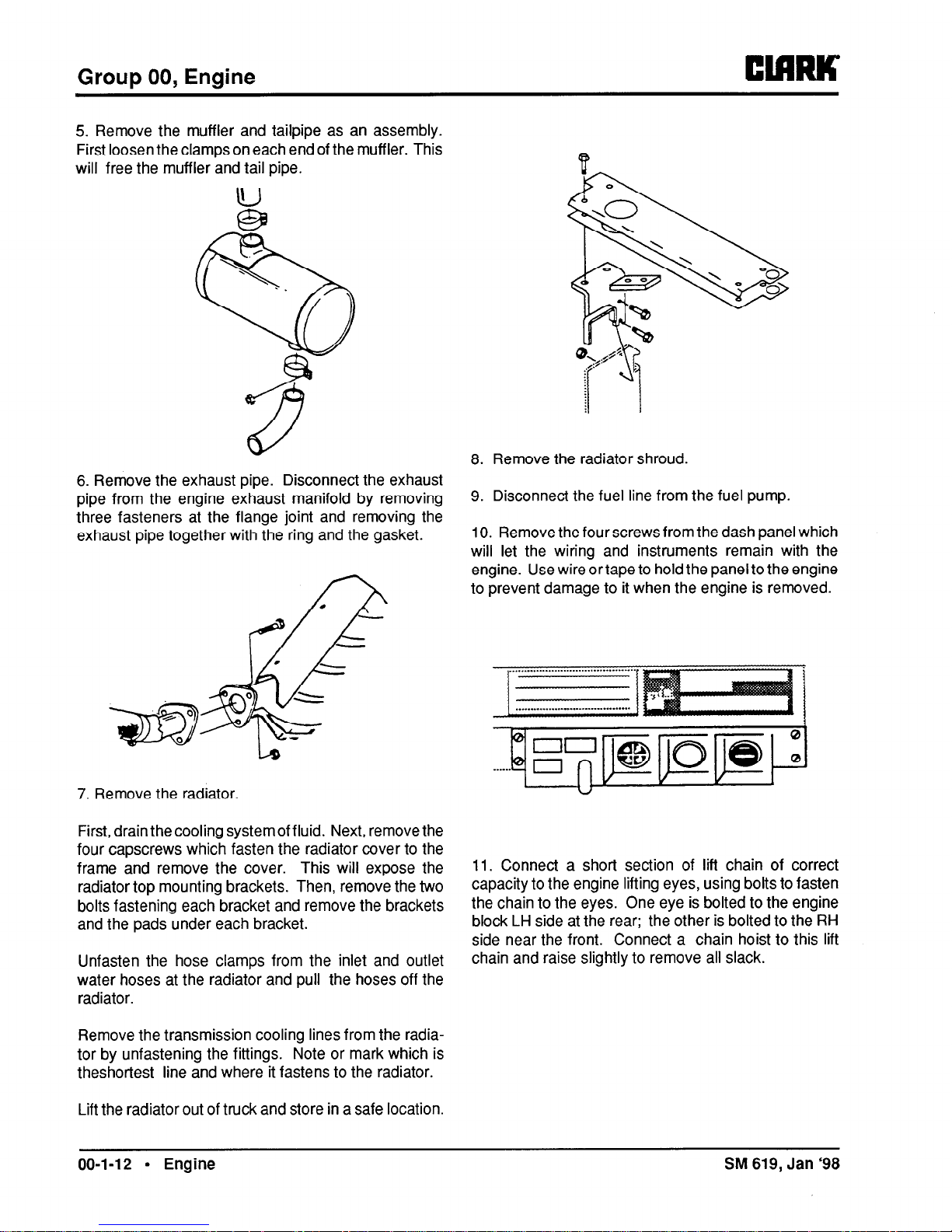
5. Remove the muffler and tailpipe as an assembly.
First loosen the clamps on each end of the muffler. This
will free the muffler and tail pipe.
6. Remove the exhaust pipe. Disconnect the exhaust
pipe from the engine exhaust manifold by removing
three fasteners at the flange joint and removing the
exhaust pipe together with the ring and the gasket.
7. Remove the radiator.
First, drain thecooling systemof fluid. Next, remove the
four capscrews which fasten the radiator cover to the
frame and remove the cover. This will expose the
radiator top mounting brackets. Then, remove the two
bolts fastening each bracket and remove the brackets
and the pads under each bracket.
Unfasten the hose clamps from the inlet and outlet
water hoses at the radiator and pull the hoses off the
radiator.
Remove the transmission cooling lines from the radiator by unfastening the fittings. Note or mark which is
theshortest line and where it fastens to the radiator.
Lift the radiator out of truck and store in a safe location.
8. Remove the radiator shroud.
9. Disconnect the fuel line from the fuel pump.
10. Remove the four screws from the dash panel which
will let the wiring and instruments remain with the
engine. Use wire ortape to hold the panel to the engine
to prevent damage to it when the engine is removed.
11. Connect a short section of lift chain of correct
capacity to the engine lifting eyes, using bolts to fasten
the chain to the eyes. One eye is bolted to the engine
block LH side at the rear; the other is bolted to the RH
side near the front. Connect a chain hoist to this lift
chain and raise slightly to remove all slack.
00-l-12 l Engine
SM 619, Jan ‘98
 Loading...