

Page 1
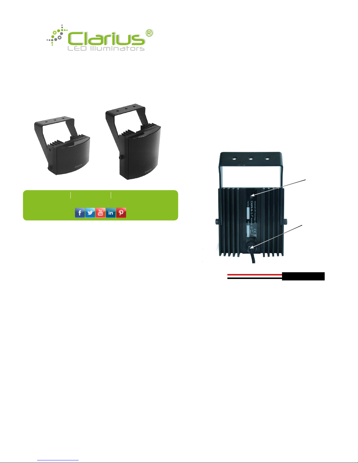
Clarius LT®
User Guide
Specification
Electronics High efciency surface mount
Dual Core LEDs™ with advanced
current limited integral control
circuitry
Beam Angles 30° or 90° models available
Lens/Beam Pattern The illuminator should be matched
to the scene and the camera lens
focal length
Wavelength 850nm
Expected Life 10 years
Consumption Clarius IS / 10W
Clarius IM / 20W
Input Voltage 12-32V DC
Operating Temp. -50° to 50°C (-58° to 122°F)
Environmental IP67
Construction Robust high quality aluminium
extrusion
Front Window Polycarbonate high transmittance
(Vandal-proof) with CleanLITE®
technology
Dimensions Clarius IS / 68 x 110 x 78mm
Clarius IM / 114 x 110 x 78mm
Weight Clarius IS / 750g (1.65lbs)
Clarius IM / 1.05Kg (2.3lbs)
Power Cable 3m (9ft).
Mount Black powder coated stainless
steel wall mount. Adjustable via M6
Allen Key (included)
Installation
Note: The illuminator is low voltage 12-32V DC
Optimum results are achieved by setting up at night and
viewing the results on a monitor.
1. Attach the illuminator mount to pan/tilt unit, wall or camera
housing.
2. Connect the lamp to a suitable low voltage supply. Ensure
that the polarity is correct
3. Commission the mains supply, camera and monitoring
equipment
4. Adjust the pan angle of the illuminator to match the
camera eld of view
5. Adjust the vertical alignment by loosening the side bolts
(one on each side of the main body) to maximise the results
6. Tilt the lamp downwards until the rear part if the required
eld of view is saturated with light, as viewed on the
monitor.
7. SLOWLY or GRADUALLY tilt the lamp upwards until the far
part of the required eld of view is illuminated correctly on
the monitor.
Power Connections
Photocell
The photocell is designed to automatically switch the lamps
on at a dusk and turn of at dawn. A high degree of hysteresis
is incorporated to void on/off switching in marginal conditions.
The unit is factory set at approximately 30 Lux On and 70 Lux
Off.
Disabling the photocell
To disable the photocell, cover the rear photocell window. This
will make the lamp turn on at all times.
Safety
WARNING: When the lamp is running, it is hot to touch. Before
touching switch off the illuminator and allow to cool for a
minimum of 10 minutes.
Do not stare directly into the lamp at a distance of less then
1.8m.
Red: +ve
Black: -ve
Photocell
window
powercord
Unit 2 Birch Business Park, Whittle Lane, Heywood, Lancashire, OL10 2SX
DESCRIPTION
Entry level infrared illuminators for CCTV, featuring state of the art
technology and installation friendly design.
• Energy efcient, low voltage operation for quick and easy
installation
• Latest high efciency SMT Dual Core LEDs
®
with advanced
electronic control circuitry deliver improved thermal management,
long life and low cost of ownership
• CleanLITE
®
self cleaning lens coating technology
• Semi covert
• Built in photocell
Page 2
Trouble Shooting
Ensure all tests are undertaken by a qualied, trained engineer
and ensure safe working practices are followed at all times.
Step 1: Basics
• Check power connection
• Ensure power is 12-32V DC
• Check the photocell is working - cover photocell, light
should turn on
• Ensure power supply is suitable rated to product - check the
specications
Step 2: Lamp Test
• Check current draw of lamp corresponds to specication
• Check current of lamp - see instructions for correct current
settings
To check lamp current remove +ve (red) lead from power
supply and connect a multimeter (set to 10A) in line with the
lamp. (One lead of multimeter in common (COM), other lead
into 10A socket of multimeter; set multimeter to read Amps).
Refer to PSU Specications for correct current settings.
Step 3: Set up Camera, Lens and Illumination
• Check alignment of lamp
• Check camera lens - fully open at night and set correctly
• Check model number to performance specication to
ensure required distance is achievable
Step 4: Call for further assistance
If the lamp is still not delivering the required performance,
please contact Technical Support for further assistance
Note down:
• Model number and serial number of illuminator
• Camera make and model
• Lens make and model
Certifications
This product complies with the European Directive
89/336/EEC Electromagnetic Compatibility and 73/23/
EEC Low Voltage Directive by meeting the following
standards:
Safety: EN60598-1:2008 Electrical Safety
EN60825-1:2007 LED/Laser Eye Safety
EMC: EN61000-6-1:2007
EN61000-6-3:2007
EN61000-3-2:2006
EN61000-3-3:1995 AMD1 & AMD2
FCC: FCC CFR Part15. 107 and 15.109
IP: IP67 in accordance with EN 60529:1992
AMD1 7643,1993 AMD2 10931,2000
WEEE: Waste Electrical & Electronic Equipment
European directive 202/96/EC
RoHS: Restriction of Hazardous Substances
European directive 202/95/EC
This symbol on the product means that the electrical and/or
electronic equipment to which it relates should be disposed of
at the end of life separately from domestic household waste.
There are separate collection systems for recycling in the EU. For
more information please contact the Local Authority or supplier
of the product.
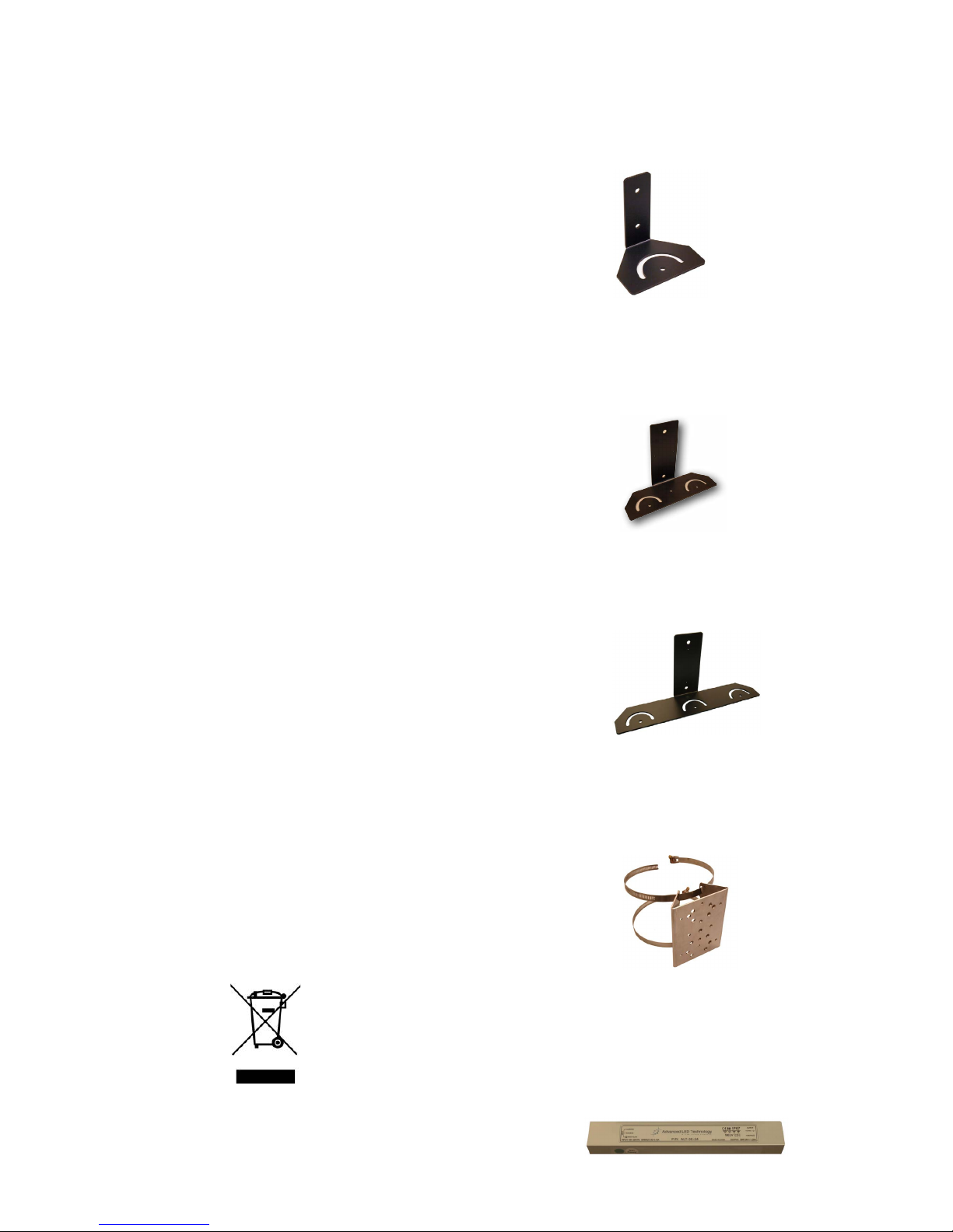
ACCESSORIES
SMB1
• ‘L’ Wall mount bracket for single illuminator
• Compatible with all Clarius infrared & white light
illuminators
• Allows up to 180 degrees rotation
• Fully adjustable (left,right, up & down)
DMB1
• Dual illuminator mounting bracket compatible with all
Clarius infrared & white light illuminators
• Doubles the angle of illumination
• Increases illumination distance by a factor of 1.4x
when using two equivalent illuminators
TMB1
• Triple illuminator mounting bracket compatible with
all Clarius infrared & white light illuminators
• Triples the angle of illumination
• Increases the illumination distance by a factor of 1.7x
when using three equivalent illuminators
PMB1
• Pole mounting bracket compatible with all Clarius
infrared & white light illuminators including SMB1.
DMB1 and TMB1
• Supplied with straps to t 7.5 to 20cm diameter pole
Recommended PSU1
• Model: ALT-30-24
• Output: 24V DC / 1.25A Max
• Input: 100-250 V AC / 0.45A 50/60Hz
• Ratings: IP67
• Dimensions: 200 x 20 x 29mm
 Loading...