

Page 1
User Guide
TM
XL50
Amplified Telephone
E
N
G
L
I
S
H
E
S
P
A
Ñ
O
L
F
R
A
N
Ç
A
I
S
Page 2

Page 3

TABLE OF CONTENTS
Introduction ........................................................................................ 4
Parts Checklist .................................................................................. 6
Quick Reference Guide .................................................................. 7
Connecting the phone ................................................................. 9
Introduction to Digital Clarity Power .....................................10
Clarity Power Boost ...................................................................10
Tone Settings ................................................................................ 12
Getting Started
Installing backup batteries .........................................................14
Desktop and Wall Mount Installations ...................................15
Placing and receiving calls .......................................................... 17
Features
Memory Storage .......................................................................... 18
Adding a memory location ........................................................18
Audio Output .............................................................................. 20
Notification Options .....................................................................21
Troubleshooting ..............................................................................24
Technical Specifications ............................................................. 27
Safety Instructions .........................................................................28
FCC Requirements and Regulations .......................................30
Warranty and Service ..................................................................33
Page 4

INTRODUCTION
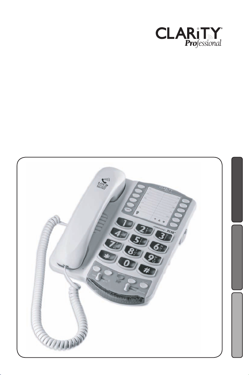
Thank you for purchasing the Clarity Professional XL50
Amplified Telephone.
Clarity is proud to offer you the only certified 60dB phone
in the market. The Clarity Professional XL50 offers our
patented Digital Clarity Power that uses digital technology
to enhance the volume and clarity of your phone conversations. This User Guide and Quick Start Guide will provide
you with the information you need to use your XL50
effectively, easily and safely. Read this manual thoroughly
before using your telephone.
Keep the manual near the telephone for easy reference.
4
Page 5

FEATURES
Digital Clarity Power™ Technology
With Digital Clarity Power, high frequency sounds are amplified
more than low frequency sounds so words are not just louder,
but clearer and easier to understand. It also provides intelligent
amplification to make soft sounds audible, while keeping loud
sounds bearable.
Tone Selection
Another added benefit of our patented Digital Clarity Power
is the ability to customize the phones performance to your
specific hearing needs. The XL50 has four available tone settings
that each provide different solutions to help you better hear
phone conversations.
Smart-Plexing Technology
Smart-Plexing is the new and advanced way that the XL50 deals
with possible feedback issues and is unique to Clarity phones.
Feedback occurs when the sound coming out of the earpiece is
detected by the microphone on the handset and is reprocessed
by the telephone. This causes the telephone to squeal or howl.
Most phones will temporarily shut off the microphone to fix this
problem, but that results in only one person being able to talk
at a time. The Clarity Professional XL50 uses a “smart plexing”
system where it enables full functionality on both ends of the
conversation at all times. Only Clarity offers such a solution
that will allow full conversation while controlling feedback.
Notification Accessories
A Wireless Lamp Flasher and Bed Shaker can be connected
to the phone to allow for a variety of ways to alert the user
that the phone is ringing. The Wireless Lamp Flasher will cause
any connected light source to flash when the phone rings. The
Bed Shaker is an accessory that will begin to vibrate when the
phone rings.
5
Page 6
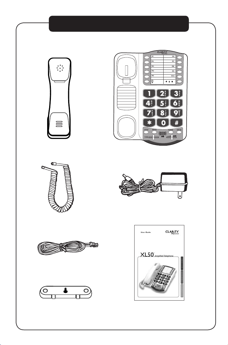
CONTENTS & PARTS CHECKLIST
BOOST
VOLUME
1 2 3 4
LAMP
AMERIPHONE
®
XL50
Handset
Handset coil cord
Telephone line cord
Base unit
AC adapter
User guideMounting bracket
6
Page 7
XL50
BOOST
VOLUME
1 2 3 4
LAMP
AMERIPHONE
®
XL50
FEATURES
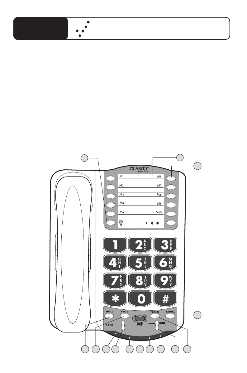
Quick Reference Guide
1 Phone Number Directory
2 Memory Button
3 Redial Button
4 Flash Button
5 Volume Slider
6 Low Battery Indicator
7 Visual Ringer
8 Boost Button
14
9 Boost/Missed calls
Voice Mail/Extension
10 Tone Control
11 Hold Indicator
12 Program Button
13 Hold Button
14 Lamp Flasher Button
1
2
10 12 13
3
6
7 9 11
8
45
7
Page 8
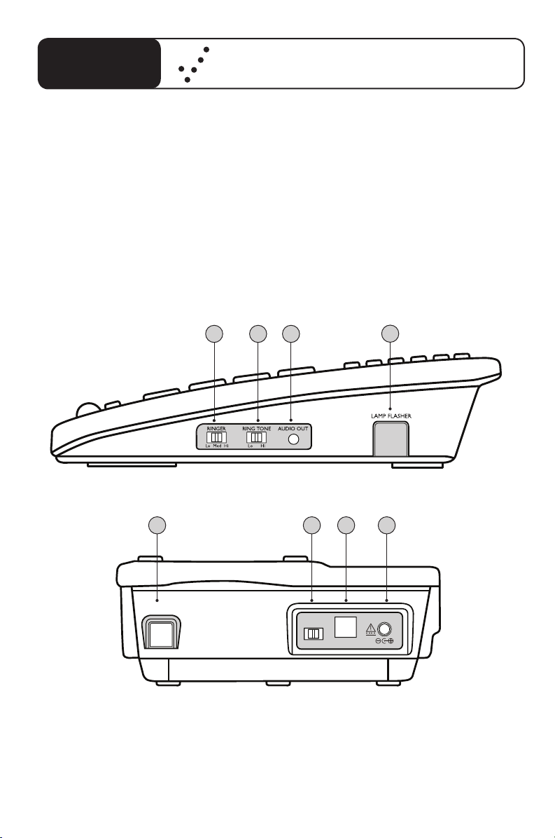
XL50
DIAL
BED SHAKER
LINE
P T
DC12V
FEATURES
Quick Reference Guide
1 Ringer Volume Switch
2 Ring Tone Switch
3 Audio Output Port
4 Wireless Lamp Flasher Port
SIDE VIEW
5 6 7 8
BACK VIEW
5 Bed Shaker Port
6 Pulse/Tone Switch
7 Phone Line Connection
8 AC Adapter Connection
1 2 3
4
8
Page 9
XL50
M
1
M
2
M
5
M
6
M
7
M
8
M
9
M
10
M
1
1
M
3
M
4
Quick Reference Guide
HOW TO CONNECT THE XL50 PHONE FOR DESKTOP USE
2
1
3
1. Connect one end of the telephone line cord to the “Line” jack on the
back of the XL50 and the other end to the phone outlet on your wall.
2. Connect the handset cord to the telephone as shown above.
3. Plug the other end into the AC jack on the telephone. Plug the AC
adapter into an electric outlet.
4. Lift the handset and listen for a dial tone. The phone is ready to use.
The XL50 phone may also be used as a wall mounted phone.
(Please see page 16 of this guide for instructions.)
9
Page 10
BOOST
VOLUME
1 2 3 4
Figure A
INTRODUCTION TO DIGITAL CLARITY POWER
Digital Clarity Power™ Technology
With Digital Clarity Power, the high frequency sounds are amplified
more than the low frequency sounds so words are not just louder,
but clearer and easier to understand. It also provides intelligent
amplification to make soft sounds audible while keeping loud
sounds tolerable.
To enable this type of technology, there is actually a computer
running information inside the phone. Each time the handset is
picked up, the computer will take a little less than a second to
engage. This means that any numbers that are dialed or words that
are spoken before the computer engages, will not be recognized
or heard by the phone.
Clarity Power BOOST Button
The XL50 has a BOOST button that controls the
loudness of the receiver. See Figure A. Once the BOOST
button is pressed, an extra level of amplification is added
over the entire range of the Volume Control. During a
call, the BOOST button can toggle the Clarity Power
function on or off according to the user’s needs. The
BOOST button will reset automatically every time the
phone is hung up for at least 5 seconds. The BOOST light
will illuminate while the BOOST function is activated.
See Page 23.
Warning: Volume may be at a high level. To protect
hearing, lower the Clarity Power Volume Control before
using the phone.
10
Page 11
-OFF
ON
-
Volume
Reset
Override
Volume Reset Override
BOOST
VOLUME
1 2 3 4
BOOST
VOLUME
1 2 3 4
On the bottom of the XL50, there is a Volume Reset
Override switch. When this is set to “On” the
Boost function is automatically enabled every time
the phone is picked up. In standard use, when the
Override is set to “Off ” the Boost function will turn
off after the phone is hung up. Setting this switch
to “On” is suggested if all the users of the phone
need the amplification. Setting this switch to “Off”
is useful when people with varying hearing ability use
the phone. See Figure B.
Clarity Power Volume Control
The Clarity Power Volume Control adjusts the level
of volume the handset both in Boost or non-Boost
modes. The volume dial provides up to 15dB of
volume before the BOOST button is activated. Once
the BOOST button is pressed, the XL50 will provide
up to 60dB of gain. See Figure C.
TONE Switch
Adjusting the TONE switch allows you to customize
your hearing experience. Since we all have different
hearing preferences we suggest exploring each
setting to find the one most comfortable for you.
The available settings are: low frequency amplification, flat amplification, Clarity Power (high frequency)
amplification, and Multi-band Compression (high
frequency) amplification. See Figure D and the overview of tone settings featured on pages 12-13.
Figure B
Figure C
Figure D
11
Page 12

OVERVIEW OF XL50 TONE SETTINGS
1
High
Amplification
Low
Amplification
Low Frequency
High Frequency
Low
Amplification
High
Amplification
1
2
3
4
The XL50 offers four different tone settings to provide an experience that
may be customized to fit a specific users need. The illustration above shows
how the four settings relate to each other and the amount of amplification
they give to the different frequencies of sound.
The following charts illustrate each tone setting separately. Read each
explanation and examine the charts to help decide what setting will be most
beneficial. In addition, make sure to listen to each setting while making a decision. The best way to choose between the settings is to listen to them all and
decide which one provides the best telephone conversation experience.
12
The first tone setting is one that emphasizes the low frequency sounds. This
is for those who have a hard time hearing lower pitched sounds.
Page 13

Low Frequency
High Frequency
Low
Amplification
High
Amplification
2
Low Frequency
High Frequency
Low
Amplification
High
Amplification
3
Low Frequency
High Frequency
Low
Amplification
High
Amplification
4
OVERVIEW OF XL50 TONE SETTINGS
The second tone is a flat amplification of all sounds. This is for the user who
wants full volume amplification for every type of sound. This is suggested if
the user is wearing a digital hearing aid while using the phone.
The third tone setting is our set Clarity Power that begins to focus more
on the higher frequency sounds and add speech intelligibility. It is a medium
between tone setting two (2) and four (4).
The fourth tone setting provides full emphasis on speech intelligibility using
Clarity’s Multi-Band Compression. Clarity MBC also enables the phone to
amplify the soft sounds to an audible level while controlling the louder sounds,
keeping them bearable. This is for the user who may be able to hear the words
being spoken, but does not understand or cannot distinguish what is being said.
13
Page 14

2
1
Figure 1
GETTING STARTED
There are five initial steps involved in setting up
your XL50
1. Insert four AA alkaline batteries for back-up in case of
AC power outage. See below.
2. Decide if you want the phone to sit on a desk or hang
on the wall.
3. Connect the telephone components. Pages 15-16.
4. Program up to eleven (11) telephone numbers to call
with the press of a memory button. See Page 18.
5. Set up Notification Options. See Page 20.
Installing the Backup Batteries
If there is a power outage, the XL50 will operate for up
to 48 hours with four AA alkaline backup batteries (not
included). If the phone is not in use, the batteries will stay
charge for several months. See Figure 1.
To install new batteries:
1. Slide open the battery compartment cover on the
bottom of the telephone. To open the battery
compartment, use a pen or similar fine point instru ment to press into small opening below the compart
ment door. This opening is pointed out with the #2
in Figure 1.
2. Install four fresh batteries. Be sure to observe battery
polarity as imprinted on the base of the compartment.
The battery indicator on the top panel will light up if
the batteries are running low.
The phone operates as a regular phone if there is no
power or battery. Certain functions of the phone do
require power however. If no power is being supplied to
the phone, it will have no indicator lights, the loud ringer
will be disabled, there will be no amplification, and the
lighted keypad will not be lit.
14
Page 15

M
1
M
2
M
5
M
6
M
7
M
8
M
9
M
1
0
M
1
1
M
3
M
4
1
2
GETTING STARTED
Connecting your Telephone
1. Carefully remove your telephone from its box. If there
is any visible damage, do not attempt to operate this
equipment. Return it to the place of purchase.
2. Check to be sure that you have all items that come
with your XL50 telephone. You should have a Hand
set, Base Unit, AC Adapter, Mounting Bracket, Han dset
Line Cord, and Telephone Line Cord.
Choosing a Location
• The XL50 requires a modular phone jack and a
standard 120 Volt outlet for operation.
• The unit should be located in an area where it is easy
to see the visual display and lighted ringer.
• Choose a location that is out of the way of normal
activities.
• The unit can be used as a desk top phone or wall
mount phone.
CAUTION: Always connect the AC adapter to the phone
before you connect it to the AC power. When you finish,
disconnect the AC power before you disconnect it from
the telephone.
Desk Mounting Instructions
Follow these instructions to place the phone on a desk or
table top using the supplied bracket.
1. Plug one end of the long flat telephone line cord into
the jack marked LINE located on the back of the
telephone. Plug the other end into the telephone wall
jack. See Figure 2
2. Insert the plug of the AC adapter into the jack marked
DC 9V located on the back of the base unit. Then plug
AC adapter into wall outlet. See Figure 2.
Figure 2
15
Page 16

M
A
N
U
A
L
AU
T
O
M
1
M
2
M
5
M
6
M
7
M
8
M
9
M
1
0
M
1
1
M
3
M
4
Figure 3
Figure 4
GETTING STARTED
3. Plug one end of the modular coiled handset cord into
the hand set. Plug the other end into the jack located
on the left side of the telephone. Place the handset in
the cradle. See Figure 3.
4. Set the TONE/PULSE switch located on the back
of the base to correct dialing mode. Please check with
your local telephone company if uncertain of the type
of service.
5. Lift the handset and listen for a dial tone. The phone is
ready to use.
Warning: Use only the power adapter provided with
this telephone. Use of any other adapter may damage the
product and result in injury.
Wall Mounting Instructions
The phone unit may be mounted on a standard wall plate.
The mounting bracket will mount on the telephone with
the larger tabs towards the bottom of the phone.
1. Pull the handset hook out of the base and reverse its
position so that the hook points up and will hold the
handset when you hang up. See Figure 4.
2. Plug one end of the short flat telephone line cord into
the jack marked LINE located on the back of the
telephone. Then run the cord through the groove on
the back of the phone.
3. Insert the tabs of the mounting bracket into the slots
in the back of the phone. Push the mounting bracket in
and down firmly until it snaps into place. See Figure 5.
16
Figure 5
Page 17

GETTING STARTED
M
1
M
2
M
5
M
6
M
7
M
8
M
9
M
1
0
M
1
1
M
3
M
4
M
1
M
2
M
5
M
6
M
7
M
8
M
9
M
1
0
M
1
1
M
3
M
4
1
2
M
A
N
U
A
L
A
U
T
O
4. Plug the flat telephone line cord into the wall plate
jack, then align the mounting bracket’s keyhole slots
with the wall plate studs and slide the base of the
phone downward to secure it on the wall.
See Figure 6.
5. Plug one end of the coiled handset cord into the
bottom of the handset. Plug the other end of the
handset into the modular jack marked HANDSET
located on the left side of the phone. Place receiver in
the cradle. See Figure 7.
6. Set the TONE/PULSE switch located on the back
of the base to correct dialing mode. Please check with
your local telephone company if uncertain of the type
of service.
7. Insert the plug of the AC adapter into the jack marked
DC 9V located on the back of the base unit. Then plug
the AC adapter into a wall outlet. See Figure 8.
8. Locate the small hook on the handset cradle on the
base. Pull the hook out and turn around so the small
lip faces upward to support the handset.
9. Lift the handset and listen for a dial tone. The phone is
ready to use.
Placing a Call
1. Lift the handset and dial the number you wish to call.
2. Press the BOOST button and turn the Clarity Power
dial to adjust volume. The BOOST button will illumi nate to indicate amplification is on.
Figure 6
Figure 7
Figure 8
1. Plug one end of the long
flat telephone line cord
into the jack marked
LINE located on the
back of the telephone.
2. Insert the plug of the
AC adapter into the jack
marked DC 9V located
on the back of the
base unit.
17
Page 18

LAMP
AMERIPHONE
®
XL50
Figure 9
BOOST
PROG
HOLD
BOOST
VOLUME
1 2 3 4
TELEPHONE OPERATIONS
Receiving a Call
When a call is received, the audible ringer will sound and
the visual ringer will flash to alert you of an incoming call.
To answer the call, lift the handset or use the headset (if a
headset is connected).
FEATURES
Memory Storage
Phone numbers can be stored into the phones memory
to enable one button dialing. The phone directory allows
space for eleven (11) different phone numbers. One space
is marked to be used to store an emergency number.
See Figure 9.
It is important to not store 911 into your phone.
This will prevent inadvertently calling an emergency
call center. Only store emergency numbers such as a
doctor, hospital, the local fire department or local
police station numbers.
18
Figure 10
Adding a Memory Location
1. Pick up the handset.
2. Press the PROG button. See Figure 10.
3. Enter the telephone number you wish to store.
4. Press the PROG button.
5. Press the desired memory location (M1- M10
and Emergency) to store the number to.
6. Place the handset back in the cradle.
Note: No audio notification will occur after the
number has been stored properly.
To change a Memory Location, reprogram using the
same procedure with the button to be changed.
Dialing a Memory Location
1. Pick up the handset.
2. Press the number on the dial pad where the
desired number has been stored.
3. The call will automatically dial.
Page 19

TELEPHONE OPERATIONS
DIAL
BED SHAKER
P
LAMP
Lamp Flasher / Bed Shaker Notification
A Wireless Lamp Flasher and Bed Shaker can be connected to the phone to allow for a variety of ways to
alert the user that the phone is ringing. The Wireless
Lamp Flasher will cause any connected light source to
flash when the phone rings. The Bed Shaker is an accessory that will begin to vibrate when the phone rings.
This function is only available with the optional Lamp
Flasher or Bed Shaker Notification Accessories.
First connect the Lamp Transmitter to the telephone and
the Lamp Switch to a nearby lamp. See Figure11.
Connect the Bed Shaker to the proper port in the phone
for use. See Figure 12.
Figure 11
Lamp Control
This function is only available with the optional Lamp
Flasher Notification Accessory. This button can be used to
turn on or off the light source to which the Lamp Flasher
is connected. See Figure 13.
Figure 12
Figure 13
19
Page 20

BOOST
VOLUME
1 2 3 4
BOOST
VOLUME
1 2 3 4
BOOST
VOLUME
1 2 3 4
Figure 14
Figure 15
Figure 16
TELEPHONE OPERATIONS
Flash
Flash is a feature that enables you to answer a call if you
have call waiting. Please contact your local telephone
company for information on subscribing to this feature.
Pressing the FLASH button while you are having a phone
conversation will pick up the second conversation and
place the first call on hold. Press the FLASH button again
to continue your conversation with the first caller.
See Figure 14.
Last Number Redial
Redial allows you to automatically redial the last telephone number you called (up to 32 digits).To use this
feature, listen for dial tone and press the REDIAL button
once. Your call will be dialed. The last number dialed will
be stored in the XL50 for you until you dial another
phone number. See Figure 15.
Hold
To put the line on hold, press the HOLD button and
return the handset to its cradle. You will notice the HOLD
indicator light comes on. To take the phone call off HOLD,
press the HOLD button again. See Figure 16.
Note: If you pick up an extension phone on the same line
when the XL50 is on HOLD, the XL50 will release the
HOLD, and you can continue your conversation on the
extension phone.
20
Figure 17
Audio Output
The AUDIO OUTPUT socket allows you to connect the
XL50 to a hearing aid, neck loop, cochlear implant or
other assistive listening devices. See Figure 17.
It is important to remember that devices compatible
with this port are intended to be used for listening only.
The phone still requires speaking into the handset for
conversation.
To use this port, plug in a compatible cable and connect it
to your assistive listening device. Speak into the handset
when you use the Audio Output connection.
Page 21

TELEPHONE OPERATIONS
BOOST
VOLUME
1 2 3 4
BOOST
VOLUME
1 2 3 4
NOTIFICATION OPTIONS
Ringer Volume
Ringer Volume can be set to one of three (3) positions
by pressing the RINGER VOLUME UP or DOWN switch
located on the right side of the telephone. See Figure 18.
The ringer settings can be checked without making the
ringer sound by pressing and holding the BOOST button
for three (3) seconds. See Figure 19.
Ringer Tone
The ringer can be set to ring at two different tones, a low
frequency sound or a high frequency sound. This provides
the user the ability to select a more favorable ringer, one
that is distinguishable and heard more easily. See Figure 20.
Figure 18
Figure 19
WARNING : RINGER VOLUME IS VERY LOUD
AND CAN DAMAGE YOUR HEARING. NEVER
PUT YOUR EAR CLOSE TO THE RINGER.
XL50 Low Battery Indicator
If the batteries are weak or not installed, the Low Battery
indicator will light up. Install fresh batteries according to
the directions above. See Figure 21.
Figure 20
Figure 21
21
Page 22

VM A IL
MI S SE D C ALL
OF F
VM A IL
MI S SE D C ALL
OF F
VM A IL
MI S SE D C ALL
OF F
BOOST
VOLUME
1 2 3 4
Figure 22
BOOST
VOLUME
1 2 3 4
Figure 23
Figure 24
Figure 25
TELEPHONE OPERATIONS
Visual Ringer
With the DC power source attached, the visual ringer
will flash to alert of an incoming call.
With the backup batteries inserted, the visual ringer will
appear brighter. See Figure 22.
Missed Call / Voice Mail Message Light
This light can flash when you have either a missed call or a
new voice mail message, or it can be turned off.
See Figure 23.
This function of the light will initially be set to off.
Note: This light will also light up if the phone line
is disconnected.
This setting is determined by the switch on the bottom
of the phone. Turn the phone over and on the bottom is
a switch with three positions. The choices are “VMAIL”,
“MISSED CALL” and “OFF.” See Figure 24.
Note: To use for voice mail notification, you must
first subscribe to voice mail messaging with your
telephone company.
If you do not have voice mail service, the same indicator
functions as a missed call indicator. It flashes if an incoming call is not answered by a person or an answering
machine after one (1) ring, provided that you set the
switch underneath the phone to Missed Calls. The light
will continue to flash until the handset is lifted or AC
power is disconnected. See Figure 25.
Note: This feature does not require any optional tele-
phone company services.
It is useful when you are away for a short time while
expecting a call. If you don’t want any notification, set
the switch on OFF. See Figure 26.
22
Figure 26
Page 23

BOOST
VOLUME
1 2 3 4
LAMP
AMERIPHONE
®
XL50
PHONE INDICATOR LIGHTS
HOLD
Indicator Light
This light will
illuminate when the
phone call is put on
HOLD. To take off
of HOLD, press the
HOLD button again.
Boost-Missed
Call-VMail
Indicator
This light will flash
when you have
either a missed
call or a new voice
mail message, or it
can be turned off.
Visual Ringer
With the DC power
source attached,
the visual ringer will
flash to alert of an
incoming call.
Low Battery
Indicator
This light will
illuminate to indicate
the backup battery
power is low. The
batteries should be
replaced to allow
the phone to be fully
functional in case
the phone stops
receiving power.
23
Page 24

TROUBLESHOOTING
No Dial Tone/Phone Will Not Operate
1. Check all phone cords and connections. Make sure they are
plugged in securely.
2. Plug unit into a different phone jack to help determine if the
difficulty is with the phone or the phone jack.
3. Switch out handset or telephone line cords.
4. Disconnect any other equipment that may be attached to
the phone.
Unable To Dial Out
1. Make sure TONE/PULSE switch is set correctly.
2. Phone may be at the end of a long line of phones (loop). Phone
may not be getting enough power from the phone line. It may be
necessary to wait for a few seconds after lifting the handset to
begin dialing.
3. The XL50 is not compatible with Digital PBX Systems. If a
standard, single line phone works on the system, your XL50
should also.
24
The Person On The Other End Cannot Hear You
1. There is an advanced computer running inside the XL50.
Sometimes after the handset is picked up, it will take a little less
than a second to engage the phone. Since it is not immediate, if
you dial a number before the computer engages, it will not receive
the entire phone number that is dialed.
2. Too many phones or phone devices on the line may effect your
phone’s transmission. As a guideline, more than five (5) phones
or phone devices may overload the phone line. Disconnect one
(1) or two (2) devices to see if that eliminates the problem. If not,
contact your local phone company for load guidelines.
3. You may not be speaking directly into the transmitter. Always speak
directly into the mouth piece in your normal tone of voice.
Page 25

TROUBLESHOOTING
Unable To Hear Phone Ringer
1. Too many phone or phone devices on a line may cause your phone
to not ring. Disconnect one (1) or two (2) of the devices to see
if the problem is eliminated. If not, contact your local phone company
for load guide lines.
2. If power is not being supplied to the phone, the extra loud ringer,
will not work.
Volume Control Does Not Work
BOOST must be activated to turn on the additional amplification.
Static On The Line
1. Your phone may be located near a touch lamp, microwave,
refrigerator or other household appliances. Try relocating your
phone to another area.
2. A cordless phone on your line may cause static. Try disconnecting
the cordless phone. This may eliminate the problem.
3. Extra devices attached to the telephone, such as CID units and
answering machines may cause static. Disconnecting the devices
may eliminate the problem.
4. If there is also a DSL service in the home, this will cause interference
on the line. That interference is then amplified by the phone, causing
a less than optimal quality of conversation. Install the phone line filter
provided by the DSL service provider to reduce the amount of
interference on the line.
Interference
1. Check cords and connections. Frayed or poorly connected cords
can cause interference. Swap cords if necessary.
2. A RFI (Radio Frequency Interference) filter can be placed on the
line to help minimize or eliminate radio or CB transmissions. Try
relocating the telephone to another area.
25
Page 26

TROUBLESHOOTING
Unable to Access Automated Systems
Automated systems used by banks, long distance voice mail and other
applications require that a phone be set to “tone” dialing. Check
the switch on the back of the phone labeled “T/P” and set to “T.”
This will enable the phone to be compatible with these automated
systems. Compatibility
If No Power is being Supplied to the Phone.
1. If the power goes out, or the AC Adapter is not properly connected to the phone, several functions of the phone will not work.
The amplification, extra loud ringer, and the lighted keypad will not
function properly.
2. The phone will drain the backup batteries very quickly. This will
cause the need for the batteries to be changed frequently and the
Low Battery indicator light to constantly illuminate.
Do I Need to Install Batteries?
Batteries are optional. They provide backup in case of a power outage. They are recommended in areas of frequent power outages. This
phone uses four (4) alkaline batteries. They will sustain the following
functions: amplification, keypad backlighting, and loud ringer volume.
26
Still Not Working?
If, after going through this checklist, the XL50 is still not functioning
properly, call Clarity at 1-800-426-3738.
Page 27

TECHNICAL SPECIFICATIONS
Amplified dB Level
60dB/118 dBSPL
Tone control range
Full range: 300 to 3000Hz using one slide control.
Dimensions
Size: 9 1/2” x 7” x 3 1/4” (24.13cm x 17.78cm x 8.25cm)
Weight: 2.52 lbs. (1.14 kg)
Power Requirements
AC Adapter: 9VDC, 300 mA
Batteries: 4 AA alkaline batteries (not included)
27
Page 28

IMPORTANT SAFETY INSTRUCTIONS
When using your telephone equipment,
basic safety precautions should always
be followed to reduce the risk of fire,
electric shock and injury to persons
including the following:
1. Read and understand all instructions.
2. Follow all warnings and instructions
marked on the telephone.
3. Do not use this telephone near a
bathtub, wash basin, kitchen sink
or laundry tub, in a wet basement,
near a swimming pool or any where
else there is water.
4. Avoid using a telephone (other than
a cordless type) during a storm.
There may be a remote risk of
electrical shock from lightning.
5. Do not use the telephone to report
a gas leak in the vicinity of the leak.
6. Unplug this telephone from the wall
outlets before cleaning. Do not use
liquid cleaners or aerosol cleaners
on the telephone. Use a damp cloth
for cleaning.
7. Place this telephone on a stable
surface. Serious damage and/or injury
may result if the telephone falls.
8. Do not cover the slots and open ings on this telephone. This tele phone should never be placed near
or over a radiator or heat register.
This telephone should not be placed
in a built-in installation unless proper
ventilation is provided.
9. Operate this telephone using the
electrical voltage as stated on the
base unit or the owner’s manual. If
you are not sure of the voltage in
your home, consult your dealer or
local power company.
10. Do not place anything on the power
cord. Install the telephone where no
one will step or trip on the cord.
11. Do not overload wall outlets or
extension cords as this can increase
the risk of fire or electrical shock.
12. Never push any objects through the
slots in the telephone. They can
touch dangerous voltage points or
short out parts that could result
in a risk of fire or electrical shock.
Never spill liquid of any kind on
the telephone.
13. To reduce the risk of electrical
shock, do not take this phone apart.
Opening or removing covers may
expose you to dangerous voltages
or other risks. Incorrect reassembly
can cause electric shock when the
appliance is subsequently used.
14. Unplug this product from the wall
outlet and refer servicing to the
manufacturer under the following
conditions:
A. When the power supply cord
or plug is frayed or damaged.
B. If liquid has been spilled into
the product.
C. If the telephone has been exposed
to rain or water.
28
SAVE THESE INSTRUCTIONS
Page 29

IMPORTANT SAFETY INSTRUCTIONS
D. If the telephone does not
operate normally by following
the operating instructions.
Adjust only those controls that
are covered by the operating
instructions. Improper adjustment
may require extensive work by
a qualified technician to restore
the telephone to normal
operation.
E. If the telephone has been
dropped or the case has been
damaged.
F. If the telephone exhibits a
distinct change in performance.
15. Never install telephone wiring during
a lightning storm.
16. Never install telephone jacks in wet
locations unless the jack is specifcally
designed for wet locations.
17. Never touch uninsulated telephone
wires or terminals unless the tele
phone line has been disconnected at
the network interface.
18. Use caution when installing or
modifying telephone lines.
SAFETY INSTRUCTIONS
FOR BATTERIES
Caution: Risk of explosion if battery is
replaced by an incorrect type.
Dispose of used batteries according
to the instructions.
1. Use only the approved battery
pack in the handset of your
cordless phone.
For Handset Unit: 3.6V
600mAHr NiMH
Rechargeable Battery
Sanik Battery Co. Ltd.:
3SNAAA60HSJ1
GPI International Ltd.:
GP60AAAH3BMJZ
For Base Unit:
Four (4) AA alkaline batteries
2. Do not dispose of the battery in a
fire as it may explode. Check with
local codes for possible special
disposal instructions.
3. Do not open or mutilate the battery.
Released electrolyte is corrosive and
may cause damage to the eyes and
skin. It may be toxic if swallowed.
4. Exercise care in handling batteries
in order not to short the battery
with conducting materials such as
rings, bracelets and keys. The battery
or conduction material may over heat and cause burns.
5. Charge the battery (ies) provided
with or identified for use with this
product only in accordance with the
instructions and limitations specified
in this manual.
6. Observe proper polarity orienta tion between the battery pack
and the battery charger.
SAVE THESE INSTRUCTIONS
29
Page 30

REGULATORY COMPLIANCE
Part 68 of FCC Rules
Information
a) This equipment complies with Part
68 of the FCC rules and the requirements adopted by the ACTA. On the
bottom of this equipment is a label that
contains, among other information, a
product identifier in the format US:
AAAEQ##TXXXX. If requested, this
number must be provided to the telephone company.
b) A plug and jack used to connect this
equipment to the premises wiring and
telephone network must comply with the
applicable FCC Part 68 rules and requirements adopted by the ACTA. A compliant
telephone cord and modular plug, RJ11C
USOC, is provided with this product. It is
designed to be connected to a compatible modular jack that is also compliant.
See installation instructions for details.
c) The REN is used to determine the
number of devices that may be connected
to a telephone line. Excessive RENs on a
telephone line may result in the devices
not ringing in response to an incoming
call. In most but not all areas, the sum of
RENs should not exceed five (5.0). To be
certain of the number of devices that may
be connected to a line, as determined
by the total RENs, contact the local telephone company. For products approved
after July 23, 2001, the REN for this product is part of the product identifier that
has the format US:AAAEQ##TXXXX.
The digits represented by ## are the
REN without a decimal point (e.g., 03 is
a REN of 0.3). For earlier products, the
REN is separately shown on the label.
d) If this telephone equipment causes
harm to the telephone network, the
telephone company will notify you in
advance that temporary discontinuance of service may be required. But
if advance notice isn’t practical, the
telephone company will notify the
customer as soon as possible. Also, you
will be advised of your right to file a
complaint with the FCC if you believe
it is necessary.
e) The telephone company may make
changes in its facilities, equipment,
operations or procedures that could
affect the operation of the equipment.
If this happens the telephone company
will provide advance notice in order for
you to make necessary modifications to
maintain uninterrupted service.
f) If trouble is experienced with this
telephone equipment, for repair or
warranty information, please contact
Clarity, 1-800-552-3368. If the equipment is causing harm to the telephone
network, the telephone company may
request that you disconnect the equipment until the problem is resolved.
g) This telephone equipment is not
intended to be repaired and it contains
no repairable parts. Opening the equipment or any attempt to perform repairs
will void the warranty. For service or
repairs, call 1-800-552-3368.
h) Connection to party line service is
subject to state tariffs. Contact the state
public utility commission, public service
commission or corporation commission
for information.
30
Page 31

REGULATORY COMPLIANCE
i) If your home has specially wired alarm
equipment connected to the telephone
line, ensure the installation of this telephone equipment does not disable your
alarm equipment. If you have questions
about what will disable alarm equipment,
consult your telephone company or a
qualified installer.
j) This telephone equipment is hearing
aid compatible.
Customer-Owned Coin/Credit
Card Phones:
To comply with state tariffs, the telephone company must be given notification prior to connection. In some states,
the state public utility commission, public service commission or corporation
commission must give prior approval
of connection.
Part 15 of FCC Rules
Information
This device complies with Part 15 of the
FCC Rules. Operation is subject to the
following two conditions: (1) This device
may not cause harmful interference, and
(2) this device must accept any interference received, including interference
that may cause undesired operation.
Your equipment has been tested and
found tocomply with the limits of a
Class B digital device, pursuant to
Part 15 of FCC rules. These limits are
designed to provide reasonable protection against harmful interference in
residential installation.
This equipment generates, uses and can
radiate radio frequency energy and, if
not installed and used in accordance
with the instructions, may cause harmful
interference to radio communications.
However, there is no guarantee that
interference will not occur in a particular installation; if this equipment does
cause harmful interference to radio
or television reception, which can be
determined by turning the equipment
off and on, you are encouraged to try
to correct the interference by one of
the following measures:
1. Where it can be done safely,
reorient the receiving television
or radio antenna.
2. To the extent possible, relocate
the television, radio or other
receiver with respect to the
telephone equipment. (This
increases the separation between
the telephone equipment and
the receiver.)
3. Connect the telephone equip-
ment into an outlet on a circuit
different from that to which
the television, radio, or other
receiver is connected.
4. Consult the dealer or an experi enced Radio/TV Technician
for help.
CAUTION: Changes or modifications
not expressly approved by the manufacturer responsible for compliance could
void the user’s authority to operate
the equipment.
31
Page 32

REGULATORY COMPLIANCE
Industry Canada Technical
Specifications
This product meets the
applicable Industry Canada
technical specifications.
Before installing this equipment, users
should ensure that it is per- missible
to be connected to the facilities of the
local telecommunications company. The
equipment must also be installed using
an acceptable method of connection. In
some cases, the company’s inside wiring
associated with a single line individual
service may be extended by means of
a certified connector assembly (telephone extension cord). The customer
should be aware that compliance with
the above conditions may not prevent
degradation of service in some situations. Repairs to certified equipment
should be made by an authorized
Canadian maintenance facility designated by the supplier.
Any repairs or alterations made by the
user to this equipment, or equipment
malfunctions, may give the telecommunications company cause to request the
user to disconnect the equipment.
Users should ensure for their own
protection that the electrical ground
connections of the power utility, telephone lines and internal metallic water
pipe system, if present, are connected
together. This precaution may be particularly important in rural areas.
CAUTION: Users should not
attempt to make such connections
themselves, but should contact the
appropriate electrical inspection
authority, or electrician, as appropriate.
The Ringer Equivalence Number is an
indication of the maximum number of
terminals allowed to be connected to a
telephone interface. The termination on
an interface may consist of any combination of devices subject only to the
requirement that the sum of the Ringer
Equivalence Numbers of all the devices
does not exceed five.
(The term “IC:” before the certification/
registration number only signifies that
the Industry Canada technical specifications were met.)
The party responsible for
regulatory compliance:
Clarity, A Division of Plantronics, Inc.
4289 Bonny Oaks Drive, Suite 106
Chattanooga, TN 37406
Phone: 1-800-552-3368
32
Page 33

WARRANTY & SERVICE
The following warranty and service
information applies only to products
purchased and used in the U.S. and
Canada. For warranty information in
other countries, please contact your
local retailer or distributor.
Limited Warranty
Clarity, a division of Plantronics, Inc.
(“Clarity”) warrants to the original
consumer purchaser that, except for
limitations and exclusions set forth
below, this product shall be free from
defects in materials and workmanship
for a period of one (1) year from the
date of original purchase (“Warranty
Period”). The obligation of Clarity
under this warranty shall be at Clarity‘s
option, without charge, of any part or
unit that proves to be defective in
material or workmanship during the
Warranty Period.
Exclusions from Warranty
This warranty applies only to defects in
factory materials and factory workmanship. Any condition caused by accident,
abuse, misuse or improper operation,
violation of instructions furnished by
Clarity, destruction or alteration, improper electrical voltages or currents,
or repair or maintenance attempted
by anyone other than Clarity or an
authorized service center, is not a defect
covered by this warranty. Telephone
companies manufacture different types
of equipment and Clarity does not
warrant that its equipment is compatible with the equipment of a particular
phone company.
Implied Warranties
Under state law, you may be entitled to
the benefit of certain implied warranties.
These implied warranties will continue
in force only during the warranty period.
Some states do allow limitations on how
long an implied warranty lasts, so the
above limitation may not apply to you.
Incidental or
Consequential Damages
Neither Clarity nor your retail dealer or
selling distributors has any responsibility for any incidental or consequential
damages including without limitation,
commercial loss or profit, or for any
incidental expenses, expenses, loss of
time, or inconvenience. Some states
do not allow exclusion or limitation of
incidental or consequential damage, so
the above limitation or exclusion may
not apply to you.
Other Legal Rights
This warranty gives you specific legal
rights and you may also have other
rights which vary from state to state.
33
Page 34

WARRANTY & SERVICE
How to Obtain
Warranty Service
To obtain warranty service, please
prepay shipment and return the
unit to the appropriate facility
listed below.
In the United States
Clarity Service Center
4289 Bonny Oaks Drive, Suite 106
Chattanooga, Tennessee 37406
Tel: (423) 622-7793 or
(800) 426-3738
Fax: (423) 622-7646 or
(800) 325-8871
In Canada
Plantronics Service Center
8112 Trans-Canada Hwy.
Ville St. Laurent. Que.
Canada H4S 1M5
Tel: (800) 540-8363
(514) 956-8363
Fax: (514) 956-1825
Please use the original container, or
pack the unit(s) in a sturdy carton with
sufficient packing material to prevent
damage.
Include the following
information:
1. A proof-of-purchase indicating
model number and date of
purchase.
2. Bill-to address.
3. Ship-to address.
4. Number and description of
units shipped.
5. Name and telephone number
of person to call, should contact
be necessary.
6. Reason for return and descrip-
tion of the problem.
Damage occurring during shipment is
deemed the responsibility of the carrier,
and claims should be made directly with
the carrier.
34
 Loading...