

Page 1

52” VideoWall Display
WN-5220-S
User’s
Guide
Page 2

1999 by Clarity Visual Systems™, Inc.
All Rights Reserved.
Contents of this publication may not be reproduced in any form without permission of Clarity Visual
Systems, Inc.
Trademark Credits
Macintosh is a registered trademark of Apple Computer Corp.
IBM is a registered trademark of International Business Machines, Inc.
Windows is a trademark of Microsoft Corp.
All other names are trademarks or registered trademarks of their respective companies.
Disclaimer
The information contained in this document is subject to change without notice.
Clarity Visual Systems Company makes no warranty of any kind with regard to this material. While every
precaution has been taken in the preparation of this manual, Clarity Visual Systems shall not be liable for
errors or omissions contained herein or for incidental or consequential damages in connection with the
furnishing, performance, or use of this material.
ii
Page 3

52” VideoWall Display
WN-5220-S
User’s
Guide
070-0026-02
Page 4

June 1999
iv
Page 5

LIMITED WARRANTY
properly used and serviced, will perform substantially in accordance with the product data sheet
and users manual, and will be free from defects in material and workmanship for 1 year following
date of shipment. This warranty does not apply to lamps (see following section for lamp warranty)
and other consumable parts.
The main illumination lamp is considered a consumable, and is warranted against failure for the
first 3000 hours of usage, or 125 calendar days, whichever occurs first. The replacement of other
consumable parts are the Buyer's responsibility.
If any Product fails to conform to the written warranty, Clarity's exclusive liability and Buyer's
exclusive remedy will be, at Clarity's option, to repair, replace or credit Buyer's account with an
amount equal to the price paid for any such defective Product returned by Buyer during the
warranty period, provided that: (a) Buyer promptly notifies Clarity in writing that such Product
failed to conform, furnishes an explanation of any alleged deficiency and obtains from Clarity a
return authorization; and (b) Clarity is satisfied that claimed deficiencies actually exist and were
not caused by accident, misuse, neglect, alteration, improper installation, repair or improper
testing. Clarity will have a reasonable time to make repairs, to replace Products or to credit
Buyer's account.
LIMITATIONS.
OTHER WARRANTIES, EXPRESS OR IMPLIED. CLARITY NEITHER ASSUMES NOR
AUTHORIZES ANY OTHER PERSON TO ASSUME ANY OTHER LIABILITIES IN
CONNECTION WITH THE SALES OR USE OF ANY PRODUCT WITHOUT LIMITATION.
CLARITY DISCLAIMS ALL OTHER WARRANTIES, EXPRESS OR IMPLIED, INCLUDING ANY
WARRANTY OF MERCHANTABILITY OR FITNESS FOR A PARTICULAR.
IN NO EVENT WILL CLARITY BE LIABLE TO BUYER OR ANY OTHER PARTY FOR
PROCUREMENT COSTS, LOSS OF PROFITS, LOSS OF USE, OR FOR ANY OTHER
INCIDENTAL, CONSEQUENTIAL, INDIRECT OR SPECIAL DAMAGES OR FOR
CONTRIBUTION OR INDEMNITY CLAIMS, HOWEVER CAUSED. CLARITY'S LIABILITY SHALL
BE LIMITED TO ACTUAL DIRECT DAMAGES NOT IN EXCESS OF THE AMOUNTS PAID TO
CLARITY BY BUYER FOR THE PRODUCT. THESE LIMITATIONS WILL APPLY TO ALL
CLAIMS, INCLUDING, WITHOUT LIMITATION, WARRANTY, CONTRACT, INDEMNITY, TORT
(INCLUDING NEGLIGENCE), STRICT LIABILITY OR OTHERWISE.
ANY WRITTEN WARRANTY OFFERED BY CLARITY IS IN LIEU OF ALL
. Clarity warrants to Buyer that the WN-5220-S (the “Product”), if
v
Page 6

June 1999
vi
Page 7

Table of Contents
Product Introduction.....................................................................................................................1
Introduction....................................................................................................................1
Features .........................................................................................................................1
Options and Accessories ..................................................................................................2
Safety.............................................................................................................................................5
Mechanical Installation.................................................................................................................9
Site Requirements ......................................................................................................... 10
Power.....................................................................................................................10
Temperature and Humidity ......................................................................................11
Flooring .................................................................................................................. 11
Clearance ...............................................................................................................12
Cooling ...................................................................................................................12
Mechanical Setup, Standard Screen ................................................................................13
Mechanical Setup, Ultra-Thin Mullion Screen ...................................................................14
Basic Steps for Alignment ........................................................................................15
Alignment Procedure in Detail ..................................................................................16
Cables ..........................................................................................................................21
Initial Setup.................................................................................................................................23
Step 1 – Power-Up ........................................................................................................23
Step 2 - Adjust the Input Signal Settings......................................................................... 25
Select the Source ....................................................................................................25
Adjust the Black Input Level - PC, MAC or RGBS Video............................................... 27
Adjust the White Input Level – PC, MAC or RGBS Video .............................................28
Comp Video/S-Video Level Adjustment .....................................................................30
Adjust the Frequency...............................................................................................33
Adjust the Phase .....................................................................................................34
Set the Sharpness ...................................................................................................35
Position the Image ..................................................................................................36
Scale the Image ......................................................................................................38
Step 3 - Adjust the Colors .............................................................................................. 39
Step 4 – Save, Recall, or Reset the Settings ....................................................................43
Turning off the System ..................................................................................................45
Turn off the Lamp, Enter Standby Mode....................................................................45
Turn off Main Power Switch .....................................................................................46
Clarity’s Big Picture™ ..................................................................................................................47
Loop-Thru of Source Video.............................................................................................50
Installing Big Picture Option Key.....................................................................................52
Other Features and Adjustments................................................................................................ 53
Curtain ...................................................................................................................53
vii
Page 8

Monitor Select .........................................................................................................54
ID ..........................................................................................................................54
Miscellaneous Controls...................................................................................................54
Set the Number of Colors.........................................................................................55
Remote Control Tone............................................................................................... 56
Flip the Image Horizontally ......................................................................................56
Flip the Image Vertically ..........................................................................................56
Auto Lamp On.........................................................................................................57
Reset Lamp Hours .........................................................................................................57
About ...........................................................................................................................59
Cleaning and Maintenance..........................................................................................................61
Lamp............................................................................................................................61
Lamp Replacement, Front, Standard Mullion Screens .......................................................62
Removing a Standard Screen Using the Screen Removal Tool..................................... 63
Lamp Replacement, Rear Access, Either Screen Type ......................................................64
Air Filter Replacement, Front or Rear Access ...................................................................64
Cleaning the Screen and Mirrors ..................................................................................... 65
Troubleshooting ..........................................................................................................................67
Power and Start-Up Problems ........................................................................................67
Common Problems and Answers.....................................................................................70
Image Problems ............................................................................................................71
Connector Pinouts.......................................................................................................................72
RGBS............................................................................................................................72
MAC .............................................................................................................................73
PC & LOOP-THRU.......................................................................................................... 73
RS-232 IN.....................................................................................................................75
RS-232 OUT..................................................................................................................75
S-VIDEO ....................................................................................................................... 76
Interface and Controls ................................................................................................................77
Rear Panel Indicators, Connectors and Controls............................................................... 77
Rear Panel Indicators ..............................................................................................77
Rear Panel Connectors.............................................................................................78
Rear Panel Controls .................................................................................................79
Remote Control .............................................................................................................80
Remote Control Functions ........................................................................................ 80
Menus ..........................................................................................................................82
RS-232 Control ............................................................................................................................89
RS-232 Control Items ....................................................................................................92
Specifications ..............................................................................................................................97
Environmental............................................................................................................... 97
Picture Control ..............................................................................................................97
Optical..........................................................................................................................98
Mechanical....................................................................................................................99
Electrical..................................................................................................................... 100
Regulatory Information ............................................................................................................103
Declaration of Conformity ............................................................................................ 103
FCC Regulations .......................................................................................................... 104
Other Certifications...................................................................................................... 104
Index..........................................................................................................................................105
June 1999
viii
Page 9

Introduction
The WN- 5220-S VideoWall is a mult i- frequency, multi-source display capable
of displaying a wide range of video sources. The clear, bright image is a
product of careful engineering and optical innovation. Setup is easy because of
light weight and simple mechanical connections. And it is fast because there
are only a few adjustments necessary to configure the image.
Product Introduction
The optional Ultra-Thin Mullion screen gives the display additional flexibility in
meeting the most demanding image quality applications. By eliminating t he
front-surf ace frame, this screen nearly eliminates the visible seam between the
displays. (Mullion: the metal edge around the screen.)
Clarity’s Big Picture™ option is a built-in data/videowall processor. Without the
need for an external processor, Big Pict ur e can scale t he source video to
accommodate any display wall size up to four high and four wide.
Features
Clarity’s products are designed and developed by experts in LCD projection
technology and offer sig nificant advantages over conventional cathode ray
tube (CRT) based systems including:
optical resolution of 800x600 pixels
•
ability to scale lower resolution sources up to 800x600
•
supports a wide variety of computer and video formats
•
superior image quality (even in high ambient light conditions)
•
substantially lighter weight – 120 lbs (55 kg)
•
significantly reduced depth (reduced footprint)
•
lack of image flicker
•
improved brightness uniformity (no “ hot spots”)
•
no convergence requirements
•
no color drifting
•
easy to service
•
fast and easy setup
•
1
Page 10

Additional Features
direct compatibility with a wide range of video and computer data
•
sources: 800x600 and 640x480 for PC and MAC; 31.5 kHz line
doubled RGBS video
with the optional S/300 electronics, 15.75 kHz RGBS video and the
•
ability to decode and display NTSC, PAL and SECAM directly
Options and Accesso r i es
Clarity’s display products can be enhanced with several accessories.
Ultra-Thin Mullion Screen
!"
The standard screen has a mullion 1/8” (3 mm ) wide.
•
– The options are:
The mullion is a strip of sheet met a l sur r ounding the
screen which holds it in place.
The Ultra-Thin Mullion Screen, or mullionless screen,
•
does not have the 1/8” (3 mm) strip of sheet metal
around the screen. The edge of t he scr een goes to
within 0.025” (0.64 mm) of the edge of the display unit,
which makes the lines between display units almost
invisible in the finished video wall.
S/300 Option - Video Input M odul e
!"
This option adds the ability to scale up the image on each
edge of the display for a better image fit when working with
multiple displays. It also adds three new source inputs:
15.75 kHz RGBS video, and composite and S-video in
both NTSC, PAL and SECAM.
Clarity’s Big Picture™
!"
This option allows a single video source to be expanded
over a video wall up to 4x4 displays, eliminating the need
for an external processor. (
display units in the video
All
wall must have this option.) Scaling and moving of t he
individual images facilitates exact matching at the borders.
June 1999
2
SRT-100 Screen Removal Tool
!"
This tool makes it easy to rem ove the nor mal mullion
screens when the displays are used in video walls, where
units are placed directly adjacent to each other. The
SRT-100 minimizes the chance of damaging the screen
and the screen’s latches. (It cannot be used with Ultra- Thin
Mullion Screens.)
SAT-500 Screen Alignment Tool
!"
This tool is essential to properly position the display units
with the Ultra-Thin Mullion Screen in a video wall. It helps
assure the correct spacing between adjacent screens in
the assembled video wall. (Cannot be used with standard
mullion screens.)
Page 11

BAS-520 Base for the WN-5220-S
!"
The BAS-520 provides a permanent attachment to
flooring.
Please contact your reseller for a current listing of available options or visit
Clarity’s website at
www.ClarityVisual.com
3
Page 12

June 1999
4
Page 13

WN-5220-S VideoWall User’s Guide
Safety
Please read this chapter carefully bef or e at tempting to install, use,
service, or repair the WN-5220-S VideoWall. There are a number of
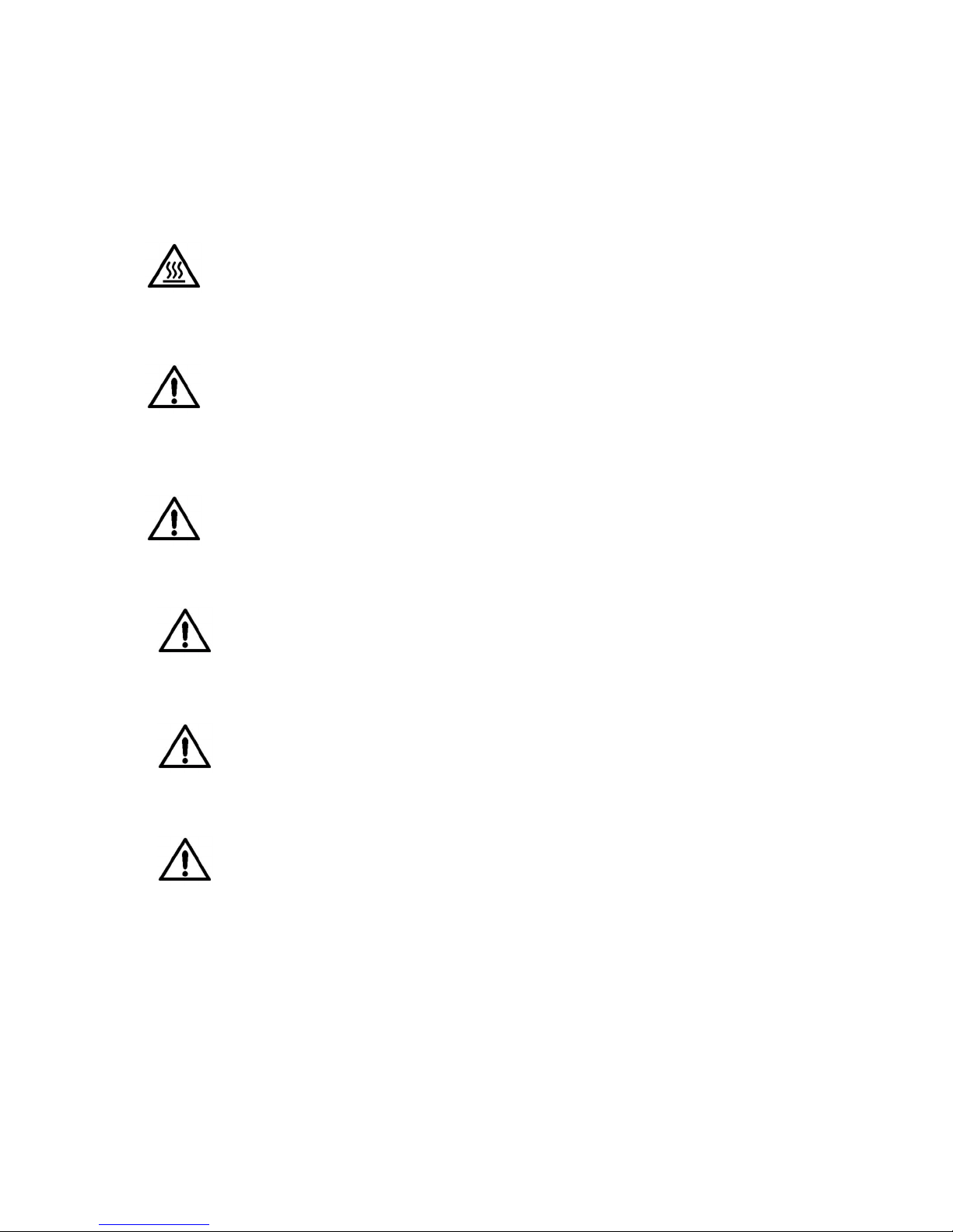
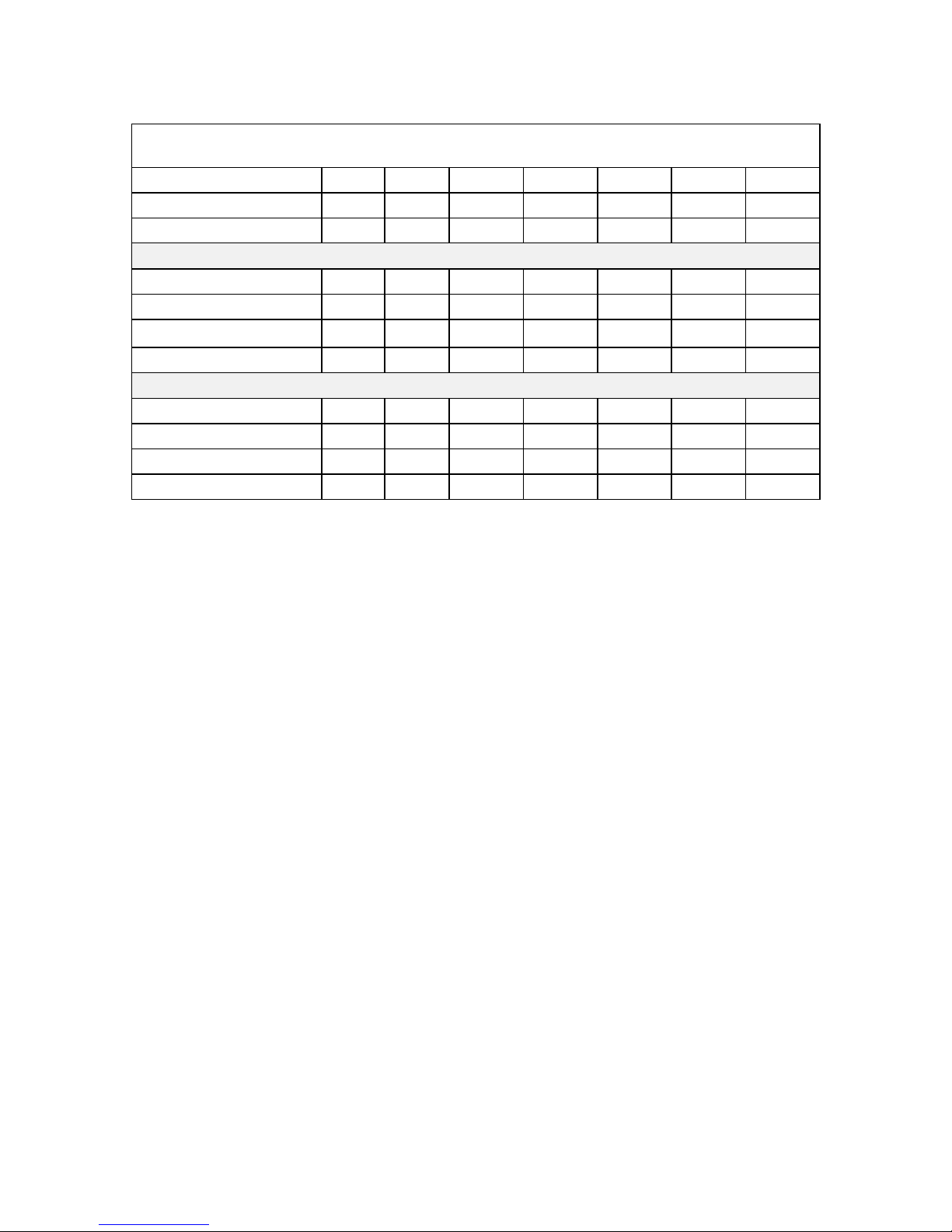
potentially dangerous areas inside the unit. T hese ar e ident ified with
the following warning labels.
Hazardous voltage inside. Can shock, burn, or cause
death. No user serviceable parts inside. Refer all
service to qualified serviceman.
5
Page 14
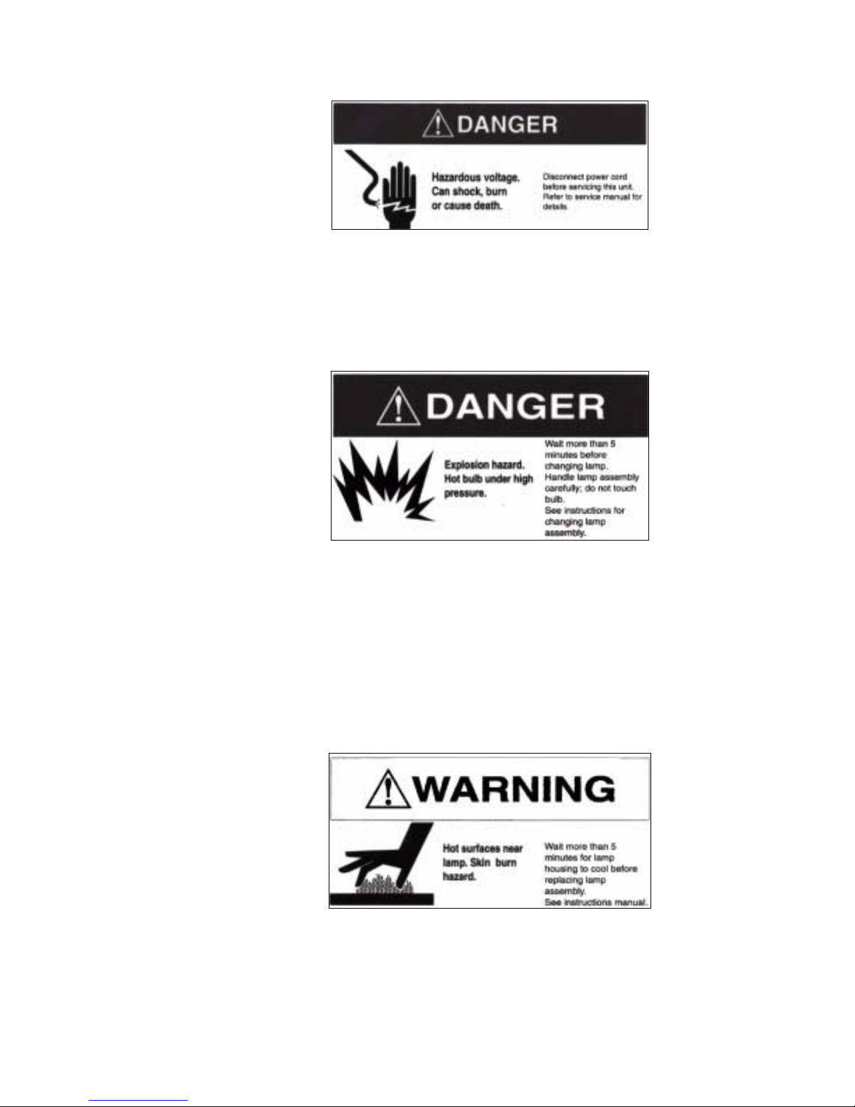
Clarity Visual Systems
Hazardous voltage. Can shock, burn or cause death.
Disconnect power cord before servicing this unit . Refer
to service manual for details.
Explosion hazard. Hot bulb under high pressure. Wait
more than 5 minutes before changing lamp. Handle
lamp assembly carefully; do not touch bulb. See
instructions for changing lamp assembly.
Hot surface near lamp. Skin burn hazard. Wait mor e
than 5 minutes for lamp housing to cool before
replacing lamp assembly. See instruction manual.
June 1999
6
Page 15

WN-5220-S VideoWall User’s Guide
UV radiation from unprotected, operating bulb. Eye
damage injury. Do not disturb light path shielding f r om
the bulb.
WARNING
Only the WN-5220- S lamp, air filter, and fuse are user
serviceable. Always turn off and disconnect power before
servicing these items. Refer all ot her service to a qualified
service center. Failure to do so could result in electrical shock,
ultraviolet radiation burns, contact heat bur ns, serious injury, or
irreparable damage to the WN-5220-S and may void your
factory warranty.
WARNING
WARNING
WARNING
The area around the projection lamp and the pr ojection lamp
assembly become extremely hot during and after use. Use
extreme caution and let the WN-5220-S’s lamp assembly cool
for 5 minutes before t ouching or replacing the lamp assembly.
The WN- 5220- S cont ains electrical interlocks that prevent
operation of the display when the front screen is r em oved. Do
not bypass these interlocks, except for servicing . Never
operate the WN-5220-S with any access panels or the front
screen removed from the unit, except for servicing. Operating
the WN-5220- S with access panels or the front screen
removed can expose service or operating personnel to
ultraviolet burns and high electrical voltages. Always wear
ultraviolet-blocking eyewear with side guards when servicing
the WN-5220- S.
The WN- 5220- S uses a high-intensity projection-lamp module.
Do not attempt to replace the projection lamp module with any
alternative light source. Doing so can cause overheating or
unacceptable image quality. Replacement lam p m odules m ay
7
Page 16
Clarity Visual Systems
WARNING
CAUTION
CAUTION
be ordered from Clarity Visual Systems, Inc. Use only the
projection lamp module specified by Clarity Visual Systems,
Inc. or an authorized Clarity Visual Systems, Inc. Service
center. Use of any other lamp voids the warranty.
Do not block the WN-5220-S cooling fan or free air movement
under, over, or around the WN-5220-S. Loose papers or other
objects should not be nearer to the WN-5220-S than 6 inches
on any side.
Air handling ducts can discharge unwanted dust or hightemperature air directly on the display. Do not oper at e t he
WN-5220-S in dust y or high-temperature conditions.
Where several WN-5220-S displays are combined vertically,
installation of the top level requir es a m inim um of 12 inches of
clearance in order to position and fasten t he display in place.
CAUTION
CAUTION
CAUTION
Some types of environmental lighting , such as incandescent, or
high-intensity discharge lamps such as metal halide or m ercury
vapor lamps create high temperatures. This can cause
excessive heating of the display. The unit should be positioned
away from lighting to prevent heat buildup.
The front screen of the WN-5220-S display can be easily
scratched and the optical quality degraded by f ing erprints.
Install the WN-5220-S in such a way that it is not exposed to
touching or possible scratching by hard objects.
Display units with Ultra-Thin Mullion screens are not
serviceable from the front .
June 1999
8
Page 17

Read the chapter on safety precautions bef ore installing and
operating the WN-5220-S VideoWall.
WARNING
WN-5220-S VideoWall User’s Guide
Mechanical Installation
Use help. The WN-5220-S weighs approximately 120 lbs
(55 kg). Do not attempt to lift or m ove the WN-5220-S without
help. Always use all four lifting handles to move or lift the WN5220-S.
The WN- 5220- S com es with either a st andar d scr een or an Ultra-Thin
Mullion Screen:
standard screen
The
•
has a mullion about 1/8
th
inch (3 mm) wide.
The mullion is a strip of sheet met al sur r ounding the screen and
holds it in place.
Ultra-Thin Mullion Screen
The
•
have the 1/8
th
inch strip of sheet metal around the scr een. The
, or mullionless screen, does not
viewing area of the screen goes right to t he edge of the display
unit. This makes the lines between display units much less
apparent in the finished video wall.
The following table shows installation specifications for common
display configurations. (The t able applies t o both the standard screen
and the Ultra-Thin Mullion Screen.)
9
Page 18
Clarity Visual Systems
Height x Width
Number of display units
1x1
Single
1x2
2 displays
2x2
4 displays
2x3
6 displays
3x3
9 displays
3x4
12 displays
4x4
16 displays
Screen Height, inches 31.3 31.3 62.6 62.6 93.3 93.9 125.2
Screen Width, inches 41.7 83.4 83.4 125.1 125.1 166.8 166.8
Weight, pounds 120 240 480 720 1080 1440 1920
115 Volts A/C Input
Current, amps 8 16 32 48 72 96 128
Power, watts 920 1840 3680 5520 8280 11,040 14,720
Heat, BTU/hr 2827 5655 11,310 16,965 25,448 33,931 45,241
Air Cond., tons .24 .47 .94 1.41 2.12 2.83 3.77
230 Volts A/C Input
Current, amps 4 8 16 24 27 48 64
Power, watts 920 1840 3680 5520 8280 11,040 14,720
Heat, BTU/hr 2827 5655 11,310 16,965 25,448 33,931 45,241
Air Cond., tons .24 .47 .94 1.41 2.12 2.83 3.77
Site Requirements
Power
Table 1
Make sure the power cord is compatible with the nominal power
source used with the WN-5220-S display.
Power Consumption
Power consumption of the WN-5220-S is 920 Watts, or approximately
8 Amps current draw at 115 VAC (4 Amps at 230 VAC). The
WN-5220-S can be configured to operate on either 90-130 VAC or
180-260 VAC nominal power sources at 50/60 Hz.
Voltage Range
The operating voltage rang e of the W N- 5220- S is set via a switch on
the power supply near the AC power plug and on/off switch.
Operation of the display at the incorr ect voltage level can cause
damage to the unit which is not covered by the warranty.
!"Select the setting labeled 115V if your power source is
between 100 and 120 Volts AC.
!"Select the setting labeled 230V if your power source is
between 200 and 240 Volts AC.
If the input voltage drops below approximately 90V (175V if the
WN-5220-S is set to the 230V setting) the display will automatically
shut down to protect itself.
June 1999
10
Page 19
WN-5220-S VideoWall User’s Guide
On a typical 20A, 115V circuit, no more than t wo WN-5220-S displays
may be installed. This allows an extra current marg in. If any circuit
used to power one or more W N- 5220- S displays is not a dedicated
circuit, the additional electrical load placed on the cir cuit by other
equipment must be considered.
WARNING
Displays that are intended for 240V configuration must have a
properly rated power supply cord and attachment plug supplied
by the installer.
WARNING
If extension cords are used for power, use only 3-prong
grounded cords sized to handle system power requirements.
Using the wrong-size extension cord can cause a fire-safety
hazard and can reduce the voltage available to the
WN-5220-S. If the extension cord is warm to the touch it is t oo
small and should be immediately removed from operation.
Temperature and Humidity
The WN- 5220- S is designed to operate over an ambient temperatur e
range of 0° to 35° C (32° to 95° F) and a humidity of 20 to 80 % R.H.
non-condensing.
Some types of environmental lighting , such as incandescent, or high
intensity discharge lamps such as metal halide or mer cur y vapor
lamps, create high temperatur es and t his can cause excessive
heating of the WN-5220-S. Displays should be positioned far enough
away from high-temperature lights to prevent heat buildup.
Nearby heat sources can cause high operating temper at ur es in the
WN-5220-S display. Minimize the display’s exposure to heating ducts,
radiators, or other external heat sources.
Flooring
A single WN- 5220- S display unit weighs appr oximat ely 120 lbs (55
kg). Befor e inst alling the WN- 5220- S, determine the structural
integrity of the flooring where it will be used. The floor should be level
and strong enough to support the combined weight of the number of
displays and other equipment used in the installation. Take special
care when installing a WN- 5220-S in a wall configuration on a
temporary structure such as a stage floor, where the flooring could
bend or collapse under the weight of the installat ion. Never st ack
more than four (4) WN-5220-S displays vertically on a tempor ar y
floor.
11
Page 20

Clarity Visual Systems
Clearance
Normal maintenance, such as lamp module and air filter replacement,
can be performed from the front or rear of the WN-5220-S. Maintain
sufficient clearance to allow easy access from t he front. A minimum of
4 feet is recommended. For full maintenance from the r ear , the
minimum recommended clearance is 3 feet .
To allow proper cooling, the minimum required clearance to the rear
of the display should be 6 inches. The minimum required clearance to
the top at the front of the unit is 6 inches. See Environmental
Specifications on page 97 for cooling requirements.
If installed in a video wall configuration, a m inim um of 12 inches to
the ceiling from the t op of the highest display is needed if the unit s
are installed from the front.
Cooling
Regardless of clearances and the gener al am bient temperature, the
most important fact or t hat affects reliable operat ion is t he temperature
and quantity of air coming int o the display. The intake air temperature
at the air filter must not exceed 95° F (35° C). If there is any doubt
about this temperature in an installat ion, r un t he displays for several
hours before taking t em per at ure measurements. Prevent problems by
replacing dirty air filters and keeping the air path clear.
June 1999
12
Page 21
WN-5220-S VideoWall User’s Guide
Mechanical Setup, Standard Screen
Install the WN-5220-S in the desired position and connect the power
and signal cables. See the following section f or an explanation of the
cabling configuration.
Figure 1 Connecting display units
To setup the WN-5220-S display in a video wall configuration, follow
these steps:
1. Grasp the screen on each side
at the bottom
2. Slip fingers between the screen
frame
3. Using both hands…
The “screen” you are removing is 2 or 3 inches thick.
Pull out at the bottom first, to separate the latchhooks from the latches. It comes out with a “pop.”
The screen should now be loose at the bottom, but
still attached at the top.
Slip fingers between the screen frame and the
display chassis, as close to the top latches as
possible and pull the top of the screen from the
latches.
Carefully remove the screen and set it aside.
13
Page 22
Clarity Visual Systems
4. Assemble the lower row first.
5. Stack the next higher row.
6. Insert a supplied fastener.
Line up the legs for the bottom row as straight as
possible.
Insert a ¼” X 2 ½” bolt through the holes as shown
in Figure 1. Tighten a nut securely on this bolt.
Secure the legs to the floor. Use the tapped 5/16-18
holes in the front and rear of the legs. You can put an
eye-bolt in this hole and secure it to the floor with a
lag screw. Or use angle bracket, screwed to the floor
and bolted to this hole in front and rear. Or use the
optional
putting the lower row of displays on it.
Before going to the next higher rows, see that the
bottom row is straight. From one end of the line, look
along the front of the displays. The line should be
straight and flat. Level is not as important as straight
and flat.
Slide the legs of each display into the mating sockets
of the display in the first (lower) row. Check it for
“straight and flat.”
Insert a bolt through the hole in side wall of the lower
unit into each leg of the unit above.
Tighten a nut on this bolt to lock the units together.
See
BAS-520
Figure 1 above
base, securing it to the floor and
7. Continue with subsequent rows
of displays
8. For added stability…
9. Check
10. Reinstall screens
Lock each display to the adjacent displays after the
row above it (if any) has been installed.
Use the rear-tapped holes in the legs of the upper
units to fasten to a solid support, such as a structural
wall.
The threaded inserts in each leg are female 5/16-18
UNC.
Check that all displays in the video wall are locked
together.
Reinstall each display’s screen.
Mechanical Setup, Ultra-Thin Mullion Screen
CAUTION
You will need these tools:
Displays with the Ultra-Thin Mullion Screens are not
serviceable from the front . Service should be performed
through the rear access cover.
a large, flat blade screwdriver
•
an SAT-500 Screen Alignment Tool ( two of these tools makes
•
installing a video wall even easier.)
black cloth tape
•
a tape measure (inches or centimeters)
•
June 1999
14
Page 23
•
•
The thin mullion display screens consist of two basic parts. There is
the screen itself and the f r ame it is held in, an assembly which is
Reta ining scre w
Finger hole
Space
Adapter Plate
Thin Mullion Screen
Figure 2 Ultra-Thin Mullion Screen
WN-5220-S VideoWall User’s Guide
1/2” open end wrench, deep-well socket, or an adjustable
wrench
5/64” Allen hex wrench
about 3” (7 cm) thick. T he scr een
attaches to the second part, an adapter
plate which is about 1/4” (6 mm) thick.
The adapter plate is mounted on the front
of the display unit.
During the alignment process, you
remove the screen from the adapter
plate, then adjust the adapter plat e t o
make its corners square and alig n
correctly with its neighbors. Then the
screen is re-installed and adjusted in or
out.
Installing a video wall with Ultra-Thin
Mullion Screens is a little more complex
than installing the wall with standard
mullion screens. Mechanical alignment is
more critical, and the larger the video
wall, the more precisely each unit must
be aligned to produce a good looking
image. The outcome of this alignment
process is partly dependent on how flat
the floor is, but it is most ly dependent on
how tightly the displays are fitted to each
other.
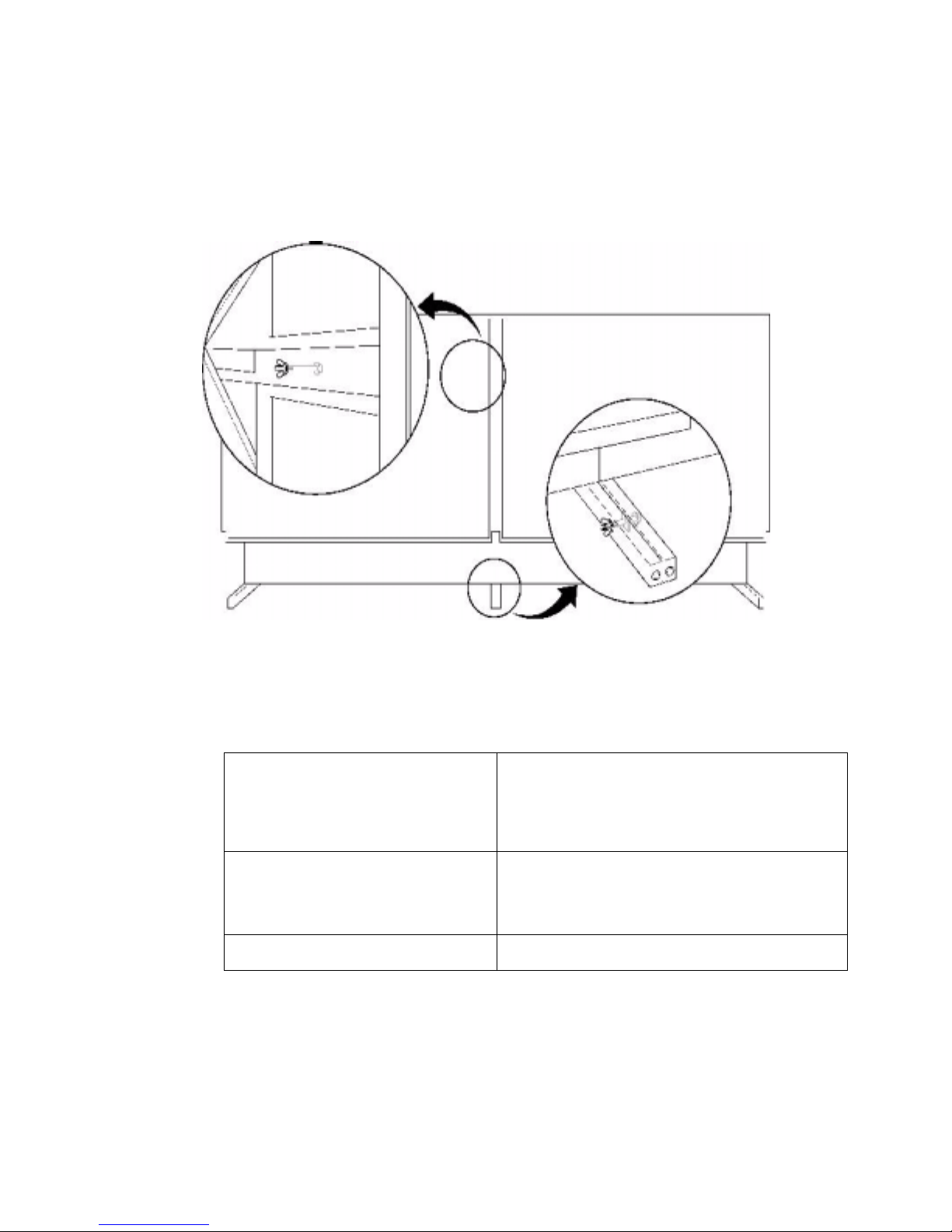
Basic Steps for Alignment
This is a summary of the steps necessary to build a video wall thin mullion
displays and align their screens. This is a
perform each step follow the summ ar y.
1. Remove the screens from all the display units.
2. Build the video wall.
3. Start with the display unit in the center of t he bot tom row. Square its
adapter plate.
4. Using the Alignment Tool, working along the bottom row in both
directions from the squared adapter plate and align each of the ot her
Adapter Plates to its neighbor.
summary
only. The details on how to
15
Page 24
Clarity Visual Systems
5. Align the adapter plates on the rest of the rows, working upward, to the
adapter plates in the bottom row.
6. Hang the screens on the bottom row and adjust them in or out so the
front surfaces (t he scr een faces) are flat with each other. Then do t he
rows above.
7. Put retaining screws in the top row and cover any holes and seams with
black tape to prevent light leak s.
Alignment Procedure in Detail
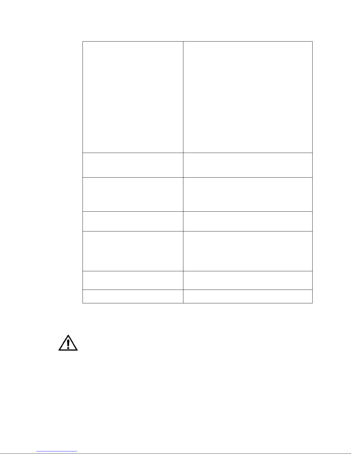
Read through all the detailed parts of each numbered step before starting it.
1. Remove the screens from all
the display units
2. Build the video wall.
.
A. Look down on the top of the screen and locate
the two retaining screws. Remove these screws,
using the 5/64-inch Allen hex wrench, and set
them aside.
B. Grab the sides of the screen, or use the finger
holes, and lift it up about half an inch (1 cm), and
remove it from the adapter plate. Set it aside.
A. Assemble the lower row first. Line up the legs for
the bottom row as straight as possible. Insert a
¼” x 2½” bolt through the holes as shown in
Figure 1. Tighten a nut securely on this bolt, but
not so tight as to bend the legs. From one end of
the bottom row, look down the row. See that all
the units are aligned, that the line of the front of
the display units does not curve forward or
backward, up or down. The straighter the first
row, the better the finished wall will be. And the
easier it will be to get in right.
B. Secure the legs to the floor. Use the tapped 5/16-
18 holes in the front and rear of the legs. You can
put an eye-bolt in this hole and secure it to the
floor with a lag screw. Or use angle bracket,
screwed to the floor and bolted to this hole in front
and rear. Or use the optional
securing it to the floor and putting the lower row of
displays on it. Stack the next higher row. Sliding
the legs of each display into the mating sockets of
the display in the first (lower) row.
C. Insert a bolt (supplied). Insert a bolt through the
hole in side wall of the lower unit and into each
leg of the unit above. Tighten a nut on this bolt to
lock the units together. See Figure 1 above.
Tighten all the bolts after you have checked for
straightness, as in Step A above.
D. Continue with higher rows of displays. Lock each
display to the adjacent displays after the row
above it (if any) has been installed. Check for
straightness on each row.
E. For added stability, use the tapped holes in the
rear of the legs of the upper units to fasten to a
solid support, such as a structural wall. The
threaded inserts in each leg are female 5/16-18
UNC.
BAS-520
base,
June 1999
16
Page 25
WN-5220-S VideoWall User’s Guide
F. Check that all displays in the video wall are
locked together. And straight.
3. Start with the display unit in the
center of the bottom row. This
will be the Base Unit. Align the
Base Unit’s adapter plate.
(If the
bottom row has an even number of
display units, choose either middle
one. This step can be done before
the wall is built, if necessary.)
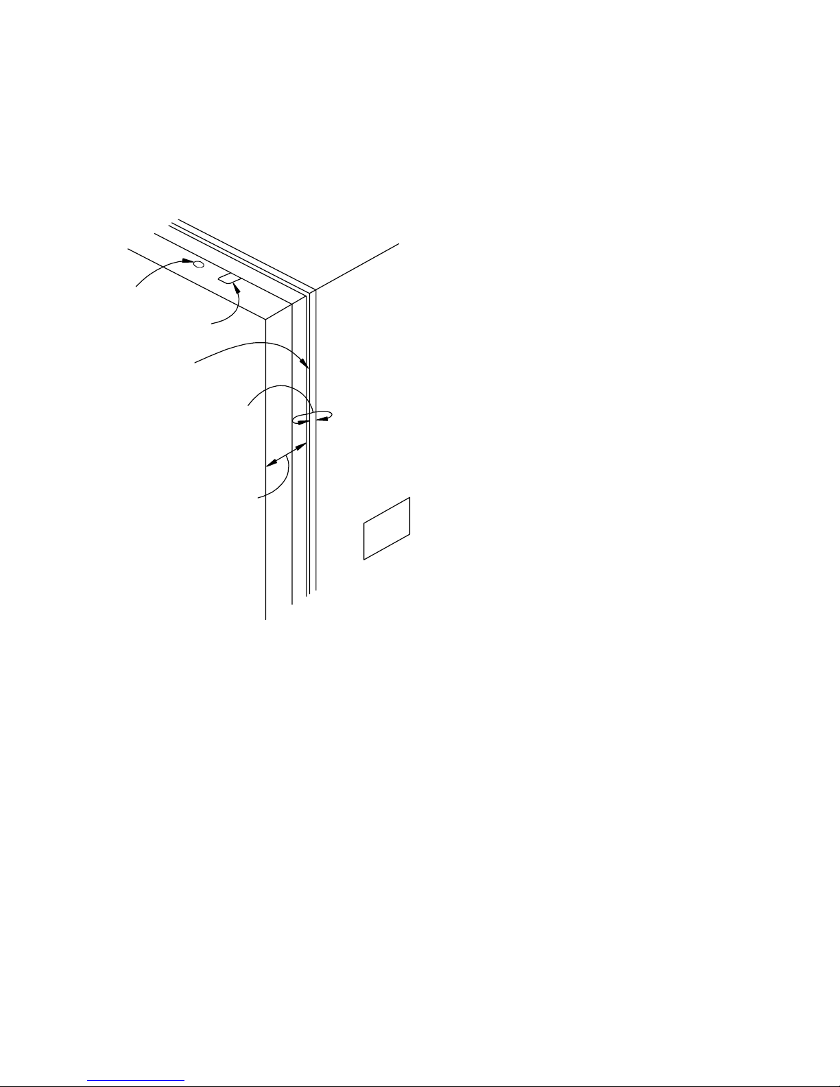
A. Look at the sides of the Adapter Frame. (See
Figure 3, below.) Starting at the top edge and
moving down you will see a large Locking Screw,
a pointed Alignment Bolt, and an Alignment Hole.
Near the middle of each side is a threaded hole
for the Alignment Tool’s spring-loaded screws.
(Do not attach the Alignment Tool yet.) At the
bottom of the side notice the Alignment Hole, the
Alignment Bolt, and the Locking Screw.
B. Look at all the Alignment Bolts of all units. They
should all be the same distance out. The factory
standard is 3/32
nd
of an inch, measured to the
base of the hex nut, or three full revolutions of the
bolt from when it is completely down against the
frame.
C. Check to see that the Adapter Frame of the Base
Unit is centered on the chassis. If the frame is not
centered on the chassis opening, for instance, if it
is offset to the left, then all the other frames will
have to be offset in this same direction. It is best if
this first frame is nicely centered on its chassis
opening.
D. Check to see that all the Locking Screws are
tight.
E. Measure the opening diagonally, from corner to
corner in both directions, and compare the
results. Be sure to measure from exactly the
same points each time. An accuracy of 1/32
inch (0.8 mm) is necessary for most applications,
but the more accurately you can do this,
particularly in the bottom center unit, the better
the video wall will be aligned and the better the
picture will look.
F. If the two measurements are the same, you have
a rectangle with perfectly square corners,
nd
4. Working along the bottom row
in both directions, align each of
the adapter plates, using the
Alignment Tool.
and you may go on to Step 4.
G. If the two measurements are not the same, within
nd
1/32
inch (0.8 mm), the frame is not a rectangle
with perfectly square corners, it is a
parallelogram.
Loosen the top Locking
Screws on each side. Move the adapter plate left
or right a bit and tighten the screws. Measure the
diagonals again. Repeat this process until you are
satisfied that the two diagonals are the same.
This means the adapter plate is a perfect
rectangle with square corners.
A. Now that the center unit adapter plate is squared,
align one of its neighbors in the bottom row.
17
Page 26
Clarity Visual Systems
g
5. Align the adapter plates on the
units above the Base Unit,
working upward.
8
6
2
B. The diagram above shows the order in which you
should align the displays in a typical video wall.
(Note: This is not the same as the Unit ID
address of the display units.)
C. The Alignment Tool fits over the seam of two
adjacent adapter plates. The Tool has six guide
pins, three on each side, and four spring-loaded
screws, two on each side. (Only two of the springloaded screws, one on each side, will be used at
a time.)
D. Position the Alignment Tool between the two
displays. One of these (#1) is already square and
the other (#2) is about to be aligned. Fit the tool
into display #1 first and attach it with the lower
spring-loaded screw. The guide pins should go
into the Alignment Holes in display #1.
E. Loosen the two Locking Screws in #2 on its right
side under the Alignment Tool and move the
adapter plate of display #2 until the guide pins go
in the Alignment Holes. Secure the Alignment
Tool to #2 with the spring-loaded screw. Tighten
the two Locking Screws on #2 under the
Alignment Tool. (Do not be concerned about the
units in the row above at this time.)
F. With the Alignment Tool still in place, check
display #2 for squareness by measuring the
diagonals. Loosen the Locking Screws on #2 that
are on the other side from the Alignment Tool,
and adjust adapter plate #2 until it is squarecornered rectangle.
G. When you are satisfied that display #2 is aligned
to display #1 and it has perfectly square corners,
remove the Alignment Tool. (If you have two
Alignment Tools, leave this first one in place, and
put the second on the other side.)
H. Go to the display on the other side of the center
display (#3) and align it to the center display,
following the steps 4.C through 4.G.
A. Start with the display above the Base Unit. Align
display #4 to display #1. Put the Alignment Tools
on either side of the Base Unit, #1. The upper
uide pin should now fit the bottom Alignment
5
4
1
9
7
3
June 1999
18
Page 27
WN-5220-S VideoWall User’s Guide
6. Hang the screens on the
bottom row and adjust them in
or out so their front surfaces
are flat with each other.
Hole of #4. Loosen the bottom Locking Screw in
#4 and make it fit. Do the same on the other side,
moving the Alignment Tool, if you have only one.
B. Measure the diagonals of #4. Loosen the top two
Locking Screws and make its corners square,
then tighten the screws.
C. Continue with display #5, working your way up the
video wall to the top.
D. When you have completed the inverted-T, use
these as a frame and align the other units to it,
working from the lower rows upward. For each
display, you should be sure it is the correct
distance vertically and horizontally from all its
neighbors and that each unit’s diagonals are
equal.
A. Hang the screens on the bottom row. Be sure the
finger holes are on the top of each screen. When
each screen is seated, pull on it slightly to make
sure it is secure at both the top and bottom.
B. Notice the seams. Are the two screens flush at
each seam? If not, note how much you will have
to adjust one of the screens to make it flat and
flush with its neighbor. Measure this amount, but
be careful not to scratch the screens. Also, sight
along the row from the end. Look down the groove
on the top of the screens. This helps to prevent
where the corners match,
but the screens are not flat. Make a diagram of
the video wall and note how far to move each
corner of each unit in or out. Try to get the wall flat
within 1/32” inch (0.8 mm)
C. Remove the screens again.
D. Working from your notes, adjust the pointed
Alignment Bolts with the ½-inch wrench. Looking
at the display from the front, each complete turn
of the bolt CW (clockwise) pulls the corner of the
screen IN (away from you) by 1/32nd of an inch
(0.8 mm).
E. Hang the screens again and check your work.
F. With the screens in place on the bottom row, put
the screens on the next row above. “Flatten” this
row in the same way, paying attention to how
these fit with the bottom row as well as with their
neighbors to the left and right.
19
Page 28
Clarity Visual Systems
7. Put retaining screws in the top
row and cover holes and seams
with black tape to prevent light
leaks.
A. When all the screens are aligned with each other
to make a flat, square video wall, put the screws
in the top row of screens to hold them in place.
B. The finger holes and the space between the
screen and the adapter plate can be a source of
light leaks, allowing stray light to hit the back of
the screen and wash out some of the picture. To
prevent this, cover the finger holes in the top row
of displays with black cloth tape. “Gaffer” tape
does a nice job of this. Masking tape is
sometimes difficult to remove cleanly. You can
check for light leaks during the video setup
process. Select “Curtain” from the main menu and
verify that the whole screen is black. It is best to
do this in the actual lighting that will be on when
the wall is used.
Figure 3 Adapter Plate Parts
Lock i n g
Screw
Alignment
Bolt
Alignment
Hole
Hole for Spri ng-
Loaded screw
Alignment
Hole
Alignment
Bolt
Lock i n g
Screw
June 1999
20
Page 29

WN-5220-S VideoWall User’s Guide
Cables
Video connections from the signal source t o the WN-5220-S depend
on the type of signal supplied by the source. The com pat ible video
inputs are; PC 800x600 (SVGA), PC 640x480 (VGA), MAC 800X600
or 640X480, and 31.5 kHz (progr essive scan) RG BS Video. The VIM300 option recognizes 15.75 kHz (interlaced) RGBS video, composit e
video, and S-Video for NTSC, PAL and SECAM. These will be
processed and displayed.
The Loop-thru video output uses a standard 15-pin VGA t ype
connector for output to an external com puter monitor or another
display. The format of t he Loop- t hru video is same as the source
video. VGA and MAC will have RGB with separate H-Sync and
V-Sync. RGBS video will come out RGBS with the composite sync on
the connector’s H-Sync pin. RGB Sync on Green sources will loopthru RGBS-Sync on Green. Displays with the VIM-300 option also
have a Composite Video and S-Video loop-thru connectors.
The video cables used should be high quality and shielded to insure
the best image quality when displayed.
Using poor quality cables can lead to picture noi se, jitter and
crosstalk.
Control data enters the display via the RS-232 In connection, and is
supplied to an adjacent display (if used) via the RS-232 Out
connector. High quality shielded cables designed for RS-232
communication should be used to ensure proper data transm ission
and control.
21
Page 30

Clarity Visual Systems
June 1999
22
Page 31

WN-5220-S VideoWall User’s Guide
Initial Setup
After the displays are installed, follow these steps for
unit:
Step 1 - Power-Up
Step 2 - Adjust the Input Signal Settings
Step 3 - Adjust the Colors
Step 4 - Save the Settings
Step 1 – Power-Up
CAUTION
CAUTION
100 Volt Users –
plug on the power supply to 115V.
115
plug on the power supply to 115V.
Volt Users -
display
each
Set the red voltage switch at t he power
Set the red voltage switch at t he power
CAUTION
1. Turn the main power
switch (next to the
power cord) to the ON
(1) position
230 Volt Users -
Set the red voltage switch at t he power
plug on the power supply to 230V.
The STBY LED flashes, indicating the power up cycle has
begun. Wait approximately three minutes until the STBY
LED is on continuously.
23
Page 32

Clarity Visual Systems
2. Press the remote
control ON button to
power up each Display
3. Check for normal
operation
You will hear a ‘beep,” and the sound of the internal fans.
The lamp will come on, but will require approximately 5
minutes to fully warm up. There is a built-in delay from
when you press the remote’s ON button to when the lamp
lights. The extent of the delay depends on the Monitor ID
Unit setting. The two switches have a total number of 256
individual Monitor ID settings.
GROUP ID numbers are 0-9 and A-F for a total of 16
different settings. Each number is equal to that
number times 16. A setting of 3 is equal to 48.
UNIT ID numbers are 0-9 and A-F for a total of 16
different settings. Each number is equal to that
number times one. A setting of C equals 12.
The Monitor ID number is the combination of the Group ID
plus the Unit ID. A Group ID number of 2 and a Unit ID
number of 5 equals a Monitor ID of 37.
The delay the time between an “on” command to the
display and the ignition of the lamp is approximately 2
seconds times the Monitor Unit ID number.
Observe the LED on the rear of each unit. When proper
power is on, the STBY LED is off, and the fan and lamp
LEDs are on. A faint glow from the lamp exhaust vent in
the rear of the unit indicates the lamp is on.
June 1999
24
Page 33

Step 2 - Adjust the Input Signal Settings
Select the Source
Source Select
Frequency
Phase
Input Level
Position
Zoom
Wall Processor
Color Balance
Curtain
Hours
Save Config
Recall Config
Reset Config
Misc Control
About
WN-5220-S VideoWall User’s Guide
Source Select Source
#
$
PC
#
$
800x600 MAC
PC
••••
[ ] Auto 9-PIN
[ ] Sync On Green BNC
[ ] Interlace C-Video
S-Video
H Freq: 00000
Lines: 000
V Rate: 00
Source Select Mode
#
$
PC
#
$
800x600
640x480
800x600
••••
[ ] Auto
[ ] Sync On Green
[ ] Interlace
H Freq: 00000
Lines: 000
V Freq: 00
(The menu with the VIM-300 option installed is pictured here.)
25
Page 34

Clarity Visual Systems
After all the displays are turned on, use t his procedure to select the
correct source. This must be done with
unit in a video wall.
each
1. On the remote
control, press
SOURCE
2. Press the
Up/Down arrow
keys and
highlight the
upper
pair of
arrows
3. Auto
#### $$$$
The Source Select menu is displayed.
Notice the menu choices of “Source” on the right side of
the menu. The current selection in shown next to the
arrows and is marked with a bullet in the right hand list.
Use the left/right keys to make this selection. (Depending
on the options installed, the unit you have may not display
all these choices.)
If you have selected a good Source in Step 2, “Auto” can
set Mode automatically. Highlight the [ ] next to Auto and
press ENTER. Auto takes information from H Freq, Lines,
and V Freq, shown at the bottom of the menu, and sets
the image size and refresh rate. Auto does this just once.
The X will appear in Auto for a very brief moment.
computer sources, always use Auto rather than
selecting the Mode manually.
Note: PCs sometimes produce a 400 line video signal.
This happens when Windows boots up or when the PC
has a fault and shows a fault message. During this time,
the display will roll, because it does not recognize 400-line
video and can’t sync to it. If this happens, and you have
no other way to see the video output of the computer,
press Source on the remote control. Then highlight Auto
and press Enter. The display will now recognize and show
the 400-line video image. (This mode cannot be saved in
memory.) After the PC’s problem is fixed, use Auto again
to reset the input mode.
For
June 1999
26
4. Sync on Green
5. Interlace
H Freq:
Lines:
V Freq:
If the Source is RGBS or MAC and the source has sync
on the green channel, press ENTER to put an X in this
box. However, Auto (See Auto above) takes care of this,
and much more, for you.
This displays whether or not Interlace is present in the
signal; you can’t change it.
Shows the horizontal frequency of the displayed signal.
You can’t change this value.
Shows the number of horizontal lines in the displayed
signal. You can’t change this value.
Shows the frame rate in Hertz of the displayed signal. You
can’t change this value.
Page 35

WN-5220-S VideoWall User’s Guide
Adjust the Black Input Level - PC, MAC or RGBS Video
(This does not apply to Composite or S-Video sources – see Comp
Video/S-Video Level Adjustment on page 30.
Source Select
Frequency
Phase
Input Level
Position
Zoom
Wall Processor
Color Balance
Curtain
Hours
Save Config
Recall Config
Reset Config
Misc Control
About
Input Level
Black Level
White Level
Black Level
(Requires black field)
Auto [ ]
#### $$$$
All
Level Sample
Red 126 000
Green 125 001
Blue 129 000
Adjusting the input levels allows the unit to display the f ull color range
of the video source. If the input levels are not pr oper ly adjust ed the
image may look washed-out or posterized.
The Black Level must be adjusted
White Level.
Note:
to color balance the displays. Matching the displays so they all
produce the same colors is done in a later step called Color Balance.
Color Balance and Level Adjust are entirely independent of each
other. Level Adjust must be done with external video signals. Color
Balance may be done with internally generated patterns.
before
adjusting the
Black Level Adjust and White Level Adjust should
be used
not
27
Page 36

Clarity Visual Systems
1. Display a black screen image from
the signal source (
built-in test patterns)
2. Press the Level button, or
highlight Level in the main menu
and press ENTER.
3. Use the up/down arrows to
highlight Black Level and press
ENTER.
4. Move the cursor to Auto and press
ENTER.
not
from the
Examples of all-black sources are a black PC Paint
screen or frame 50882 on Reference Recordings, “A
Video Standard” test disk. Note: It is not necessary
for the entire screen to be black. The area of interest
is within 100 pixels of the upper left corner of the
Black Level menu.
The Input Level menu is displayed.
The Black Level menu is displayed
The display will automatically seek the black level of
the input signal and adjust the A/D converter to it.
Adjust the White Input Level – PC, MAC or RGBS Video
(This does not apply to Composite or S-Video sources – see Comp Video/SVideo Level Adjustment on page 30.)
Source Select
Frequency
Phase
Input Level
Position
Zoom
Wall Processor
Color Balance
Curtain
Hours
Save Config
Recall Config
Reset Config
Misc Control
About
Input Level
Black Level
White Level
White Level
(Requires white field)
Auto [ ]
All
Level Sample
Red 128 255
Green 128 255
Blue 128 255
#### $$$$
June 1999
28
Page 37

WN-5220-S VideoWall User’s Guide
Adjusting the input levels allows the unit to display the f ull color range
of the video source. If the input levels are not pr oper ly adjust ed the
image may look washed-out or posterized.
The input black level must be adjusted to match the source
before adjusting the input white level!
1. Display an all-white image from
the signal source (
built-in test patterns)
2. Press the Level button, or
highlight Level in the main
menu and press ENTER.
3. Use the up/down arrows to
highlight White Level and press
ENTER.
4. Move the cursor to Auto and
press ENTER.
not
from the
Examples of all-white sources are a white PC Paint
screen or frame 50823 on Reference Recordings, “A
Video Standard” test disk. It is not necessary for the
entire screen to be white. The area of interest is
within 100 pixels of the upper left corner of the White
Level menu.
The Input Level menu is displayed.
The White Level menu is displayed
The display will automatically seek the white level of
the input signal and adjust the A/D converter to it.
29
Page 38

Clarity Visual Systems
Comp Video/S-Video Level Ad justment
Source Select
Frequency
Phase
Input Level
Position
Zoom
Wall Processor
Color Balance
Curtain
Hours
Save Config
Recall Config
Reset Config
Misc Control
About
Video Controls
Brightness 128
Contrast 128
Saturation 128
Hue 128
Blue Only [ ]
Sample
R:010 G:008 B:149
This menu selection is only available when the source selected is
Comp Video or S-Video in units with the VIM-300 option installed. It is
not available when PC, MAC or RGBS sources are selected.
Brightness:
This adjusts the overall lightness and darkness of the
image.
Contrast:
Increases the difference between light and dark parts of
the image.
Saturation:
Hue:
Changes the tint of images to be more gr een or m ore
Adjusts the am ount of color the image has.
magenta colored.
1. Press the remote control LEVEL
button
2. Display an all-black image from
not
the source (
test patterns)
from the built-in
Brings up the Video Controls menu (must have Comp
Video or S-Video selected as a source).
Frame 50882 on Reference Recordings, “A Video
Standard” test disk is an all-black image.
June 1999
30
Page 39

WN-5220-S VideoWall User’s Guide
3. Adjust Brightness
4. Display an all-white image from
the source
5. Adjust Contrast
Set the Sample values for R, G and B as close to 001
as possible while keeping the Brightness number as
high as possible.
If all the initial Sample values (R, G, & B) are greater
than 001, then reduce the Brightness number until
the first Sample value reaches 001.
If the initial Sample values are showing 001, then
increase the Brightness number until all Sample
values are 002 or greater. Stop adjusting when the
last Sample value goes from 001 to 002.
If Brightness is decreased while the Sample values
are at 001, the color range for the displayed image
will be decreased.
Frame 50823 on Reference Recordings, “A Video
Standard” test disk is an all-white image.
Set the Sample values for R, G and B as close to 254
as possible while keeping the Contrast number as
low as possible.
If all the initial Sample values are less than 254 then
increase the Contrast number until the first Sample
value reaches 254.
If the initial Sample values are showing 254 then
decrease the Contrast number until all Sample
values are 253 or less. Stop adjusting when the last
Sample value goes from 254 to 253.
If Contrast is increased while the Sample values are
at 254, the color range for the displayed image will be
decreased.
6. Display a standard SMPTE Color
Bar pattern
7. Enable the Blue Only function
8. Adjust Saturation
A SMPTE Color Bar pattern is available at frame
17177 on Reference Recordings, “A Video Standard”
test disk.
Select the Blue Only option with the up/down arrows
and press ENTER to enable it. At this point the
screen will show only shades of blue.
Adjust Saturation up or down until the large color
bars at the each end of the pattern match the smaller
color bars beneath them.
31
Page 40

Clarity Visual Systems
9. Adjust Hue
10. Exit the Video Controls m enu
Adjust Hue up or down until the two central color bars
match the smaller color bars beneath them.
Press the PREV MENU button on the remote. This
will exit the menu and de-select Blue Only at the
same time.
June 1999
32
Page 41

WN-5220-S VideoWall User’s Guide
Adjust the Frequency
(This control has different effects with computer and video sources.)
Source Select
Frequency
Phase
Input Level
Position
Zoom
Wall Processor
Color Balance
Curtain
Hours
Save Config
Recall Config
Reset Config
Misc Control
About
Frequency Select
096
For RGBS, Composite and S-video sources –
Use the FREQ function to adjust the image’s horizontal width.
1. Press the remote control FREQ
button
2. Press the Left/Right arrow keys
Displays the Frequency Select menu. Observe the
horizontal width of the image.
Expand or contract the image horizontally.
For Computer (PC or MAC) sources –
Use the FREQ function to match the internal sampling clock of the
display to the incoming video data.
1. Turn Sharpness on
In the main menu, highlight Misc Control and press
Enter. If there is
Sharpness and press Enter.
an X for Sharpness, highlight
not
33
Page 42

Clarity Visual Systems
2. Display an image containing
many on/off (black/white)
transitions
3. Press the remote control FREQ
button
4. Press the left/right arrow keys
5. Press PREV MENU
A checkerboard pattern works best. One of the “fill”
patterns in Windows 95 Paint has this. Start Paint
program found under Accessories. Select Image,
Attributes, Black and White, OK, Yes. Select View
and see that Color Box is checked. Choose the Fill
tool (paint jar spilling over). In the bottom row of
black/white shades, click the 9
Click in the drawing area. Choose View, View Bitmap
to fill the computer screen with this pattern.
With MAC OS 8.0, look for a checkerboard pattern in
File, Control Panel, Desktop Patterns.
With Sharpness
correct and does not match the input source, you will
see large vertical bands in the pattern.
The FREQ adjustment menu is displayed.
The vertical bands will disappear when the frequency
matches the incoming signal.
Exit the FREQ menu.
enabled
th
box from the left.
, if the FREQ setting is not
Adjust the Phase
This setting is important for computer input. It has no effect with
Composite or S-Video sources.
Source Select
Frequency
Phase
Input Level
Position
Zoom
Wall Processor
Color Balance
Curtain
Hours
Save Config
Recall Config
Reset Config
Misc Control
About
Phase Select
028
June 1999
34
Page 43

WN-5220-S VideoWall User’s Guide
Use the PHASE button to adjust the phase of the internal sampling
clock relative to the incoming data. This adjustment is usually not
necessary for most applications, but can be used to eliminate some
types of video noise.
1. Press the remote
control PHASE
button
2. Press the
Left/Right arrow
keys
3. Press PREV
MENU
The PHASE adjustment menu is displayed.
Adjust to produce the best image quality. For computer
applications, use the same large area checkerboard as for
the FREQ adjustment. Incorrect Phase will show up as
horizontal streaks of random noise. This shows most
clearly with Sharpness ON.
Exit the PHASE menu.
Note: If the display unit is part of a video wall which is being fed by an
external multiplexer, a potential problem exists for Frequency and
Phase settings. The default vert ical r at e is 60Hz, which is correct for
normal computer sources.
Set the Sharpness
Source Select
Frequency
Phase
Input Level
Position
Zoom
Wall Processor
Color Balance
Curtain
Hours
Save Config
Recall Config
Reset Config
Misc Control
About
Misc Control
[X] Sharpness
[X] 16M Colors
[X] Buzzer Enable
[ ] Flip Horz
[ ] Flip Vert
[ ] Auto Lamp On
[ ] Test Patterns
35
Page 44

Clarity Visual Systems
Use the Sharpness menu to toggle Sharpness O n/ O ff. In general, the
sharpness should be off (no X) for composite and S-video sources,
and on (with X) for PC, MAC, or RGBS sources. Shar pness controls
an internal filter that r educes som e t ypes of video noise and softens
the edges.
1. Press the remote
control MENU
button
2. Press the up/down
arrow keys
3. Press ENTER
4. Press the up/down
arrow keys
5. Press ENTER
6. Press PREV MENU
Displays the main menu.
Move the cursor to the Misc Control selection.
The Misc Control menu is displayed.
Move the cursor to the Sharpness Selection.
Use the ENTER key to toggle sharpness on or off.
On
for PC, MAC, RGBS; of f for Comp and S-video.
Exit the Misc Control menu.
Position the Image
Source Select
Frequency
Phase
Input Level
Position
Zoom
Wall Processor
Color Balance
Curtain
Hours
Save Config
Recall Config
Reset Config
Misc Control
About
Position
%
"#" "$
&
Use the arrow keys to adjust the position of the image on each
display unit.
June 1999
36
Page 45

WN-5220-S VideoWall User’s Guide
1. Press the MENU
button on the
remote control
2. Press the
Up/Down arrow
keys
3. Press ENTER
4. Press the remote
control arrow
keys
Displays the main menu.
Move the cursor to the Position selection.
Displays the Video Position menu.
Position the image. It is easiest to see the effect of
Position when the image is a some form of geometry
pattern, one that exactly defines the edges of the image.
Note: W hen t he image is expanded with Zoom, as it is when Wall Mode is on, the
Position control has two movement speeds, fine and coarse. At first, the
movement is in fine steps, the smallest st eps possible. After 8 fine steps, the
movement is coarse, moving faster in lar ger steps. If the direct ion of movement is
changed, Position goes back to fine steps for the next 8 steps. This means you
may have to pass the position you want, then back up.
Detailed explanation: W hen using Big Picture for a 2x2 wall, each pixel in the
original picture (the
For the first 8 clicks of the Position control, the image moves 1
picture) is displayed with four
input
output
pixels in a 2x2 block.
output
pixel at each
click, the smallest amount t he im age can move electronically. After 8 clicks, the
image moves by
pixels or 2 screen pixels per click, which moves the image
input
faster. When you move the image in a new direction, the Position contr ol r evert s t o
the 1-output-pixel rate, the slowest rate .
For Composite or S-Video displays, Position speed works a little differently. For the
first 8 clicks of t he remote control, Position moves the imag e one
before. After 8 clicks
horizontally
expansion. So, for a 2x2 wall, the 9
pixels instead of two. For this 2x2 wall, the 9
, the image moves by two times the Big Picture
th
horizontal click moves the image four output
th
vertical
click moves the image two
output
pixel, as
output pixels.
37
Page 46

Clarity Visual Systems
Scale the Image
Use the arrow keys to adjust the size of the im age on each display.
Source Select
Frequency
Phase
Input Level
Position
Zoom
Wall Processor
Color Balance
Curtain
Hours
Save Config
Recall Config
Reset Config
Misc Control
About
Zoom Factor
Left
Right
Top
Bottom
- +
"#" "$
"#" "$
"#" "$
"#" "$
[ ] Lock
[ ] Default
W:0640
H:0480
June 1999
38
1. Press the MENU
button on the
remote control
2. Press the Up/Down
arrow keys
3. Press ENTER
Displays the main menu.
Move the cursor to the Zoom selection.
Displays the Zoom Factor menu.
Page 47

WN-5220-S VideoWall User’s Guide
4. Scale the image
Step 3 - Adjust the Colors
Source Select
Frequency
Phase
Input Level
Position
Zoom
Wall Processor
Color Balance
Curtain
Hours
Save Config
Recall Config
Reset Config
Misc Control
About
Color balancing is essentially balancing the brightness and color of all
the lamps in the video wall, so you do not need to color balance the
displays for each source. The color balance inf ormation is saved in
memory in only one location, not for each source.
The goal of color balancing t he displays is to match the luminance
and white color of all the displays in video wall, and then match the
intermediate gray shades. Therefore, color balancing is accomplished
with all displays on in the finished video wall. (If you have only one
unit, color balancing is not very important. )
Select an edge of the image that needs to be expanded or
compressed (Left, Right, Up or Down). It is easiest to see
the effect of Zoom when the image is a some form of
geometry pattern, one that exactly defines the edges of the
image.
Selecting the Lock feature causes the image to scale the
same amount in the opposite direction. If you scale the
Right, the Left will scale by the same amount. Similarly, Up
and Down
The Default feature scales the image back to 800x600 or
640x480 pixels, depending on the source.
Note: Resetting the Scale to default settings will also clear
any Position changes that have been made.
Color Balance
Wht Gry
All
####$$$$ ####$$$$
Red 031 007
Green 031 007
Blue 031 007
39
Page 48

Clarity Visual Systems
The color balance menu provides control over the individual RED,
GREEN, and BLUE settings to balance the white color, as well as an
ALL adjustment to control the overall lum inance. I n addition, similar
control for the RED, G REEN, and BLUE set tings is provided to adjust
the balance of the gray shades without affecting the white balance.
For white balancing
selections have a number associated with them between 0 and 31.
Zero is the darkest and 031 the brig htest. The ALL selection allows all
of the balance settings to be adj ust ed sim ultaneously. The up/down
arrow keys moves the cursor from All t o Red, Green, Blue in the
White colum n, then All, Red, Green, and Blue in the Gr ay column,
then back to All in the White column again. The left/right arrow keys
increment and decrement the brightness number.
For gray balancing
settings have a number associated with them between 0 and 7. Zero
is the darkest and 007 the bright est .
The following chart shows the relationship of t he m enu item
adjustments.
, the individual RED, GREEN, and BLUE color
, the individual RED, GREEN, and BLUE balance
1. Display an all-white
image
2. Open the Color
menu
3. Maximize all settings
4. Identify the leastbright display in the
system
5. Luminance match
the displays
6. Color balance the
displays – white
mode
On each display in the video wall, open the Misc Control
menu, select Test Pattern and choose White.
Press the Color button on the remote control, or choose
Color Balance from the main menu and press Enter.
Adjust the WHT setting of
and the GRY setting of ALL displays to 007.
The darkest display is already as bright as it will ever be. This
display will serve as a baseline to which the other displays
will be adjusted, since it cannot be adjusted to be brighter.
Note: The baseline display does not have to be the middle
one. It should be the darkest one, wherever it is in the wall.
Beginning with the display next to the baseline display, adjust
the ALL settings on the white levels to approximately match
the luminance (brightness) of the baseline unit.
Adjust the relative amounts of RED, GREEN, and BLUE in
the white (WHT) column to achieve the best match in color
and luminance to the baseline display.
If a color appears to need to be increased, but that color is
already up as high as it can go, then the other two colors can
be reduced. For instance, if you need the white to be have
more red, but red is already at 031, reduce the green and
blue. This will make the display look more red.
ALL
displays so they are at 031
7. Adjust the next
display
June 1999
40
Adjust each of the displays for white balance, working
outward from the baseline unit. Do not go to the next step of
adjusting for Gray until you are satisfied that all the displays
look the same for a white image.
Page 49

WN-5220-S VideoWall User’s Guide
8. Display a 50% gray
image
9. Identify the least
bright unit again
10. Color balance the
displays – 50% gray
mode
On each display in the video wall, open the Misc Control
menu, select Test Pattern and choose 50% Gray.
Find the unit that looks the darkest. This may not be the
same one that was the darkest one with a White test pattern.
This is the baseline unit for Gray
Adjust the relative amounts of RED, GREEN, and BLUE in
the gray (GRY) column to achieve the best match in color
and luminance to the baseline display.
The following chart shows the relationship of t he m enu item
adjustments.
Color Increase will: Decrease will:
All Increase the overall luminance
(brightness)
Red Change white toward red Change white toward cyan
Green Change white toward green Change white toward magenta
Blue Change white toward blue Change white toward yellow
Note: If one color needs to be increased, but that color is already as high as it can go, then the
other two colors can be decreased.
Decrease the overall luminance
(brightness)
A helpful technique to use when adjusting the color s and gray shades is to
“overshoot” as you adjust to emphasize the eff ect that the current adjustment
is having to the overall image, and then to back off to f ine t une. This helps to
give an intuitive feel for the pr ocess.
It is often helpful t o switch between the internal white and gray patterns and
actual video images to fine tune the system. Avoid mak ing major changes
when adjusting to the video images because this can throw off the white or
gray balance. Remember also that the Input Level adjustment has a large
effect on color. I f Input Level adjustments have not been made, color balance
for live video will be difficult. However, you may adjust Color Balance
or after
you do the Input Level adjustment. They do not affect each other –
before
that is, an adjustment in Color Balance does not affect the Input Level
adjustment, and vice versa – but they must both be adjusted pr oper ly f or the
screens in the cube to match in color balance, luminance and black level.
Do not adjust Color Balance with Red, Green and Blue test patterns. This is
a method sometimes used with CRT displays, and it will not work with these
Clarity displays.
After you have color balanced all the units, save the setting s for each unit. It
does not matter which source-mode combination you save, because color
balance data is saved once for all sources and modes. You should not have
41
Page 50

Clarity Visual Systems
to color balance the displays again until you change a lamp. However, lamps
near the end of their lif e m ay beg in t o change color, so it is a good idea to
check color balance occasionally.
June 1999
42
Page 51

Step 4 – Save, Recall, or Reset the Settings
After all adjustments have been made, Save the set t ings. There is a
separate Save location for each source in each mode – PC at
800x600, PC at 640x480, RGBS at 31.5 MHz, RGBS at 15.75 MHz,
etc. After you have adjusted the displays for one source, save these
settings before going to the next source and adjusting it. (Remember,
you only have to do the color balancing once.)
The Save, Recall, and Reset menus look alike and oper ate in the
same way, so the explanation for Save will tell you how the Recall
and Reset menus operate. (Resetting does
where settings are saved. See Figure 4 later in this section.)
Source Select
Frequency
Phase
Input Level
Position
Zoom
Wall Processor
Color Balance
Curtain
Hours
Save Config
Recall Config
Reset Config
Misc Control
About
Source
Save Configuration
# $
#### $$$$
Save MAC
9-PIN
BNC
C-Video
S-Video
Mode
Save Configuration
#### $$$$
# $
Save 800x600
WN-5220-S VideoWall User’s Guide
overwrite the memory
not
ALL
ALL PC
PC
All
••••
All
••••
ALL 640x480
43
Page 52

Clarity Visual Systems
1. Press the remote control MENU
button
2. Press the Up/Down arrow keys
3. Press ENTER
4. Press the Up/Down arrow keys
to highlight the
arrows
5. Press the Left/Right arrow keys
6. Press the Up/Down arrow keys
to highlight the
arrows
7. Press the Left/Right arrow keys
8. Press the Up/Down arrow keys
to highlight Save (or Recall or
Reset)
#### $$$$
#### $$$$
upper
lower
pair of
pair of
The Main menu is displayed.
Move the cursor to the Save Config (or Recall Config
or Reset Config) selection.
The Save Config (or Recall Config or Reset Config)
menu is displayed.
This is the Source selection area. The list of sources
is shown in the right column, with the current
selection preceded by a bullet
the arrow symbols.
Use the left/right buttons to choose the Source you
want to Save/Recall/Reset.
This is the Mode selection area, where you will
choose the modes that will be Saved/Recalled/Reset
for the previously selected Source. There is a
separate memory for
Use the left/right buttons to choose the Mode you
want to Save/Recall/Reset. (If the Source is “ALL,”
the only choice for Mode is also “ALL.”)
Press ENTER. A new menu appears as shown
below.
each
••••
and stated next to
source in
each
mode.
Save Configuration Sure
PC
#### $$$$
ALL
#### $$$$
Save
Are you sure?
Yes No
9. Press the Left/Right arrow keys
to highlight Yes
Press ENTER. The settings will be
saved/recalled/reset for the Sources and Modes you
chose. A brief message appears, replacing Yes No
with Saving Settings, Recall Settings, or Restore
Defaults. Then the highlight goes back to the top.
Shortcut: Unless you have made changes to a source or mode that
you
do not
want to save, it is easiest and safest to Save All sources,
All modes.
June 1999
44
Page 53

WN-5220-S VideoWall User’s Guide
Note: Resetting to fact or y default settings does
settings in memory until you Save them.
Rec all
Act ive
Settings
Save
Figure 4 Block diagram of memory system
Res et
Saved
Memory
destroy the saved
not
Factory
Def ault
Values
Turning off the System
Turn off the Lamp, Enter Standby Mode
Use the remote to turn of f the lamp and enter standby mode. The
main power switch on the back of the power supply is left on and the
unit remains in standby mode until turned on again.
1. Press the remote control OFF
button – or the hard-wired
REMOTE ON/STBY switch – or
the POWER button on the rear
connector panel
The unit is placed in the standby delay mode and the
lamp is shut off and locked out for 3 minutes. The fans
continue to operate during lockout to ensure proper
cooling. Three beeps will sound if an attempt is made to
turn on the units during the 3 minute lockout.
During the standby delay cycle the STBY LED on the rear
connector panel will blink.
45
Page 54

Clarity Visual Systems
Turn off Main Power Switch
Turn off the m a in power switch
for servicing or moving the
only
display, or if the display will not be used for an extended period of
time. If the unit is t ur ned off at the main power switch, the 3-minut e
power up delay is required when the unit is turned on again.
1. Turn off main power switch
The main power switch is located next to the AC power
plug at the back of the display.
June 1999
46
Page 55

WN-5220-S VideoWall User’s Guide
Clarity’s Big Picture™
Wall Processor Setup Instructions
These are the basic steps to follow to display a single image over an entire wall of
displays. Big Picture works with any video wall up to 4x4. Big Picture can be setup
and saved for each video source, so you can switch between sources while
maintaining the specific magnification and position settings for each source.
To determine whether a particular display unit has Big Pictur e, open the main menu
by pressing Menu on the remote control. If Wall Processor is
items, this unit does not have Big Picture.
one of the listed
not
1. Build the wall
2. Select the source
3. Adjust the image settings
4. Disable wall mode
5. Reset Zoom
6. Center the image
Install the wall and attach source and power cables as
described in earlier sections.
Use an amplifier/splitter device (distribution amplifier)
from the source or, if you are using loop-thru, use short,
shielded cables to minimize noise and image jitter.
In the menu for
use Big Picture.
As described in Step 2, Step 3, and Step 4 in earlier
sections, adjust black and white levels for each display;
set phase and frequency; color balance the wall.
Open the Wall Processor menu and make sure that the
Wall mode
checked. Do this for
Set Zoom in the menu to the default width and height of
800x600 or 640x480, depending on the Source and
Mode.
Find the edges of the image using the arrow buttons in
the Position menu to move the image.
For standard mullions, each mullion covers 3 pixels of
the image and each button press in the Position menu
moves the image one line or pixel at a time. Move the
image so that 3 pixels on each side of the image are
behind their respective mullions. For Ultra-Thin Mullion
screens, one pixel should hide behind each mullion.
When you move the standard size (not zoomed) image,
if you find that more or fewer than 3 pixels (or one pixel)
are hidden, then the optical image size needs to be
adjusted. Do not Zoom the image to accomplish this.
feature at the bottom of the menu is
display, select the source that will
each
display.
each
not
47
Page 56

Clarity Visual Systems
7. Set each display’s address
Assign each display a unique address using the Unit
ID knob. (The Group ID setting has no effect on Big
Picture.)
The address of the display in the upper left corner (as
seen from the front)
be zero. The addresses of
must
the other displays must increase left to right, top
bottom, increasing by one for each display. Therefore,
the display in the lower right corner (as seen from the
front)
has the highest address.
always
2x2 example $
0 1
(Seen from the
front)
3x3 example $
2 3
0 1 2
3 4 5
6 7 8
June 1999
48
Page 57

WN-5220-S VideoWall User’s Guide
8. Set the Wall Size on each
display
Open the Wall Processor menu. Enter the horizontal
and vertical wall size. Each display’s menu should
show the same horizontal and vertical wall size.
Each display should show a different Current Unit
value. This value represents its location in the wall.
Source Select
Frequency
Phase
Input Level
Position
Zoom
Wall Processor
Color Balance
Curtain
Hours
Save Config
Recall Config
Reset Config
Misc Control
About
If this unit has Big Pictur e,
you will see a menu like this:
Wall Processor
Wall Size:
Horizontal: 002
Vertical: 002
Current Unit: 01
Misc:
[ ] Calc wall pos
[ ] Wall mode
If this unit does not have Big Pictur e,
you will see a menu like this:
The Big Picture option is not
installed. Please see the
About menu for contact
information on purchasing
the Big Picture option.
9. Put each display into Wall
Mode
Move the menu cursor to the Calc wall pos line and
press the ENTER button. This calculates the position
of the selected display within the image and puts the
display into Wall Mode. Each display will now show
only its segment of the overall image.
Do this with each display in the wall and exit the Wall
Processor menu.
49
Page 58

Clarity Visual Systems
10. Fine tune the wall image
11. Save the settings
If there are other video sources on different input connectors that will
use Big Picture, go throug h t his whole process for each video source.
Then save these settings.
Loop-Thru of Source Video
Loop-thru works in differ ent ways depending on the t ype of source.
Slight degradation of the image may occur as each loop-thru stage is
encountered. This may indicate the need f or a distribution amplifier.
The Composite or S-Video inputs
connectors.
If the previous steps were done correctly, the image in
each display should not need to be adjusted by more
than two lines in any direction.
If an adjustment to the image must be made, use the
Zoom menu to move only the edge that needs
adjustment.
Open the Save Config menu and save settings for the
current Source and Mode on each
described above in
the Settings
Step 4 – Save, Recall, or Reset
on page 43.
display
, as
have their own separate loop-thru
If the source video is PC or MAC
, the same signal is output f r om the
LOOP-THRU connector, which can be connected to the next unit’s PC
input.
If the source is RGB with separate composite sync at 31.5 kHz
(progressive scan), it will come out the LOOP-THRU connector as
RGB with the composite sync on the connector’s H-Sync pin and
separated V-Sync on the V-Sync pin. Feed this to the next unit’s
RGBS connector. It might also work to feed this to the next unit’s PC
connector.
If the source is RGB Sync on Green at 31.5 kHz
(progressive), it will
come out the LOOP-THRU connector as RGB-Sync on Green, plus
composite sync on the H-Sync output pin, and separated V-Sync on
the V-Sync pin. Feed this to the next unit’s RGBS connector. It might
also work to feed this to the next unit’s PC connector .
If the source is RGBS at 15.75 kHz
LOOP-THRU connector will also be 15.75 kHz.
(interlaced), the output from the
It will not work
to loop
this output to the next display’s PC input, because the PC input is
expecting 31.5 kHz. To loop RGBS at 15.75 t o t he next display, m ake
an adapter to go from 15- pin t o 9- pin using the wiring diagram below.
Standard 15-pin-to-9-pin adapters m ay also be available from some
computer stores. Connect the first display’s LOOP-THRU output to t he
next display’s 9-pin RGBS input. Alternatively, use a 15-pin to 4-BNC
adapter cable. These are also usually available from electr onics or
computer stores.
June 1999
50
Page 59

WN-5220-S VideoWall User’s Guide
Source video
RGBS 15.75 kHz
15-pin t o 9- pin
adapter ca ble
LOOP-THRU
connector
1
2
3
13
6
15-p i n
9-pin of "next" display
RGBS
connector
1
2
3
4
6
51
Page 60

Clarity Visual Systems
Installing Big Picture Option Key
The Big Picture Option Key enables the functions and features
associated with Clarity’s Big Picture™. For Electronics Modules with a
2x7-pin connector, the Big Picture Opt ion Key can be f ield- inst alled.
This 2x7 connector is next to the power connector, which comes from
the power supply. (Clarity’s Big Picture cannot be field installed to
Electronics Modules that do not have a 2x7 connector.)
The Option Key consists of and integ r at ed Printed Circuit Board
Assembly and Cable Harness. Included as part of the Pr inted Circuit
Board Assembly are 2 adhesive backed nylon PC Board mounts. To
install it, follow these steps.
1. Turn off the power
2. Plug in the
connector
3. Mount the circuit
board
4. Turn on power
If the display is on, turn it off with the remote control
(or by pressing the button on the rear panel). Wait
for the fans to stop (3 minutes). Turn off the power
with the switch at the power supply input and
remove the power cord.
Plug the connector of the Big Picture Option Key
into the 2x7 connector on the Electronics Module.
Remove the protective backing from the PCB
mounts. Apply the mounts and board assembly in a
vertical orientation to the back of the small mirror
mount.
Connect the power cord and start the display as
usual. Note: The Big Picture Option Key can be
installed without turning off the power. However, the
Electronics Module must be re-started from a nopower state to recognize the presence of the key.
June 1999
52
Page 61

WN-5220-S VideoWall User’s Guide
Other Features and
Adjustments
The following features and adj ust m ents are available via the remote.
Curtain
Source Select
Frequency
Phase
Input Level
Position
Zoom
Wall Processor
Color Balance
Curtain
Hours
Save Config
Recall Config
Reset Config
Misc Control
About
Curtain Select
[ ] Curtain On
1. Press the
CURTAIN button
on the remote
2. Press CURTAIN
again
Displays a black screen instead of the input signal.
Displays the input signal.
53
Page 62

Clarity Visual Systems
Monitor Select
1. Press MON SEL
on the remote
2. Press MON SEL
again
ID
1. Press ID on the
Remote
2. Press ID again
Miscellaneous Controls
The Misc Control menu contains:
Sharpness
16M Colors
Buzzer Enable
Horizontal Flip
Vertical Flip
Auto Lamp On
Test Patterns
Disables all remote functions, except MON SEL, on the
display to prevent the unit from unintended adjustment
while adjusting other units. Also used to prevent stray IR
radiation from other sources from affecting this unit.
Restores remote functions on the display.
Displays the Monitor ID as selected by the Monitor ID
switch in the rear of the unit.
Removes the display of the Monitor ID position
June 1999
54
Page 63

WN-5220-S VideoWall User’s Guide
Source Select
Frequency
Phase
Input Level
Position
Zoom
Wall Processor
Color Balance
Curtain
Hours
Save Config
Recall Config
Reset Config
Misc Control
About
Misc Control
[X] Sharpness
[X] 16M Colors
[X] Buzzer Enable
[ ] Flip Horz
[ ] Flip Vert
[ ] Auto Lamp On
[ ] Test Patterns
1. Press the MAIN
MENU button on
the remote
2. Press the
up/down arrow
keys
3. Press ENTER
Set the Number of Colors
1. Press the
up/down arrow
keys
2. Press ENTER
The Main menu is displayed.
Move the cursor to the Misc Control selection.
The Misc Control menu is displayed.
Move the cursor to the 16M Colors selection.
Select between 256k and 16M colors. Normally, the full 16
million color palette is used.
55
Page 64

Clarity Visual Systems
Remote Control Tone
1. Press the
up/down arrow
keys
2. Press ENTER
Move the cursor to the Buzzer Enable selection.
Press ENTER to toggle the remote control buzzer on or
off.
Flip the Image Horizontally
1. Press the
up/down arrow
keys
2. Press ENTER
Move the cursor to the Flip Horz selection.
Flips (reverses) the displayed image horizontally.
Flip the Image Vertically
1. Press the
up/down arrow
keys
2. Press ENTER
Move the cursor to the Flip Vert selection.
Flips (reverses) the displayed image vertically.
June 1999
56
Page 65

WN-5220-S VideoWall User’s Guide
Auto Lamp On
Reset Lamp Hours
After a lamp change, use t his m enu t o reset the lamp hour timer to
zero. The system hour timer displays the total hours that power has
been applied to the display with the power supply switch on. The
system hour timer cannot be reset. Lamp hours accrue when the
display is running (FAN and LAMP LEDs are on solid).
1. Press the
up/down arrow
keys as required
2. Press ENTER
Source Select
Frequency
Phase
Input Level
Position
Zoom
Wall Processor
Color Balance
Curtain
Hours
Save Config
Recall Config
Reset Config
Misc Control
About
Move the cursor to the Auto Lamp On selection.
When enabled, the lamp will automatically come on after
the 3 minute standby timer has elapsed.
Lamp Hours: 0243
System Hours: 0886
Reset Lamp Hours?
[ ] Yes [X] No
Was Lamp Changed?
[ ] Yes [ ] No
57
Page 66

Clarity Visual Systems
1. Press the MAIN MENU
button on the remote
2. Press the up/down
arrow keys
3. Press ENTER
4. Press left/right arrow
keys
5. Press ENTER
6. Press left/right arrow
keys
7. Press ENTER
The Main menu is displayed.
Move the cursor to the Hours selection.
The Lamp Hours menu displays the current number of
lamp operating hours. Replace the lamp at 3000 hours.
This menu also shows total system hours.
Use the left or right arrow keys to highlight the Yes
selection.
Press the ENTER button to proceed in resetting the lamp
hours to zero.
At this point a warning will prompt ‘Did You Replace The
Lamp?’ If the lamp was replaced, use the left or right
arrow keys to highlight the Yes selection.
Press the ENTER button to proceed in resetting the lamp
hours to zero.
June 1999
58
Page 67

WN-5220-S VideoWall User’s Guide
About
This displays the Clarity Visual Systems contact inform at ion. It also
displays the version of firmware being used. ( The Project, Version,
Build and Date values will vary among units. The Project and Build
numbers are of concern to manufacturing only.)
Source Select
Frequency
Phase
Input Level
Position
Zoom
Wall Processor
Color Balance
Curtain
Hours
Save Config
Recall Config
Reset Config
Misc Control
About
Clarity Visual Systems
9025 SW Hillman Court
Suite 3122
Wilsonville, OR 97070
USA
Tel(503) 570-0700
Web www.ClarityVisual.com
Project: 573-0500-00
Version: Rev A
Build: 0673
Date: Fri, Mar 12, 1999
59
Page 68

Clarity Visual Systems
June 1999
60
Page 69

WN-5220-S VideoWall User’s Guide
Cleaning and Maintenance
Once the W N-5220-S is set up and adjusted, periodic maintenance will
consist of cleaning the display and replacing consumable par t s such as
the lamp and filter. Use the pr ocedur es in this section to remove and
replace WN-5220- S m odules as needed to maintain trouble-free
operation.
Lamp
Before you remove the lamp, switch off the WN- 5220- S with the r em ote
control, or press the black POWER button on the electronics module,
and allow the lamp cooling cycle to finish (3 minutes). T hen switch off
the power at the rear panel AC switch.
The WN-5220-S has two screen options:
standard screen
The
•
The mullion is a strip of sheet met al surrounding the screen which
holds it in place.
Ultra-Thin Mullion Screen
The
•
have the 1/8
viewing area of the screen goes right to the edge of the display unit.
This makes the lines between display units much less apparent in
the finished video wall.
With standar d scr eens, electrical interlocks prevent operation when the
front screen is removed. Do not operat e t he display with any access
panels or the front screen removed from the unit, except when required
for servicing. Operating the display with access panels or the front
screen removed can expose service or operating personnel to
ultraviolet burns and high electrical voltages. Always wear ultravioletblocking eyewear with side guards when servicing the display.
For Standard Screens, removing the screen provides service access to
other replaceable modules from the front of the display. Service access
for units with Ultra-T hin Mullion Screens is from the rear only.
th
inch strip of sheet metal around the scr een. The
has a mullion about 1/8
, or mullionless screen, does not
th
inch (3 mm) wide.
61
Page 70

Clarity Visual Systems
Lamp Replacement, Front, Standard Mullion Screens
CAUTION
Follow these steps to remove the standard, wider mullion screen and
replace the lamp, if the display unit is not built into a video wall. Read all
the steps before starting.
For the standard screens, with the wider mullion, the screen
may be removed by hand from stand-alone displays without
damaging the screen. Where screen edges are adj acent to
each other in a video wall, removing the screen without
screen removal tool may damage the female par t of the screen
latch. In video wall configurations, use the SRT-100 Screen
Removal Tool (see instructions below and Options on page 2)
to prevent damage to the screen.
a
1. Turn off the power
2. Unplug power cord
3. Remove screen
4. Unplug lamp
connector
5. Unhook the lamp
6. Remove the lamp
Switch off the WN-5220-S using the remote and allow the cooling cycle
to complete (3 minutes) before switching off the AC power at the rearpanel switch.
Remove the AC power cord from the WN-5220-S.
If this display unit is part of a completed video wall, see the instructions
below on “Removing a Standard Screen Using the Screen Removal
Tool.” Then go to Step 4.
Grasp the screen at each side of the bottom and pull out to separate the
latch-hooks from the latches. It comes out with a “pop.” The screen
should not be loose at the bottom, but still attached at the top.
Slip your fingers between the screen frame and the display chassis, as
close to the top latches as possible and pull the top of the screen from
the latches. Don’t twist the screen as it comes off the latches.
The lamp connector is next to the reflector fan. Unplug the connector by
pulling it up.
Unhook the two latches holding the lamp module to the optical
assembly.
Lifting up on the handle, tilt the lamp module away from the latches until
it can be pulled free of the optical assembly.
7. Install new lamp
8. Reset the Lamp Hours
June 1999
62
Carefully remove from the display by lifting the lamp module straight up
to clear the fans, and then withdrawing.
Replacement is the reverse of the above procedure. After installing the
lamp module, ensure that the high-voltage connector is in place and that
the latches are securely latched before replacing the screen or the lamp
service access cover.
Reset the lamp hours in the menu.
Page 71

WN-5220-S VideoWall User’s Guide
Removing a Standard Screen Using the Screen Removal Tool
5. Find the bumps on
the side mullions
6. Insert the removal
tool
7. Squeeze the handle
of the SRT-100
8. Repeat for all four
corners
On both sides of the screen, near the top and bottom, the
mullion is slightly lifted from the screen material, forming a
little bump. The removal tool fits here.
The small hook on the removal tool slips under the bump in
the mullion. The other side of the tool should press against the
mullion of the neighboring screen.
Squeezing the handle of the removal tool pulls one screen out
far enough to let it “pop” out at that corner. The tool uses the
neighboring screen for leverage.
Remove the screen carefully and set it aside.
These 2 parts push
against the mullion
of t he n ei ghb ori ng
scree n.
This hooks un der
the bu mp i n t h e
mullion
Figure 5 SRT-100, Screen Removal Tool
63
Page 72

Clarity Visual Systems
Lamp Replacement, Rear Access, Either Screen Type
WARNING
Befor e ser vicing t he display, always switch the AC power off at
the
panel power switch and remove the power cord. When
rear
the WN-5220- S VideoWall is connected to t he electrical mains,
some circuits still contain line voltage, even when power is
switched off.
CAUTION
Do not
the lamp or reflector. O ils from the skin will cause
touch
these surfaces to become etched when the lamp is operated,
dramatically shortening the lif e of the lamp.
1. Turn off the power
2. Unplug power cord
3. Remove screen or
lamp access cover
4. Unplug the lamp
5. Unhook the lamp
Switch off the WN-5220-S using the remote and allow the cooling cycle
to complete (3 minutes) before switching off the AC power at the rearpanel switch.
Remove the AC power cord from the WN-5220-S.
Unfasten the 8 quarter-turn screws on the lamp access cover and
remove the cover.
The lamp connector is next to the reflector fan. Unplug the connector by
pulling up on it.
Unhook the two latches holding the lamp module to the optical
assembly.
6. Remove the lamp
7. Install new lamp
8. Reset the Lamp Hours
Lifting up on the handle, tilt the lamp module away from the latches until
it can be pulled free of the optical assembly.
Carefully remove from the display by lifting the lamp module straight up
to clear the fans, and then withdrawing.
Replacement is the reverse of the above procedure. After installing the
lamp module, ensure that the high-voltage connector is in place and that
the latches are securely latched before replacing the screen or the lamp
service access cover.
Reset the lamp hours in the menu.
Air Filter Replacement, Front or Rear Access
Length of time between air f ilt er replacements depends on the
environment in which the display is operated. Air filter cleanliness
should be periodically checked and the air filter r eplaced when dirty, at
a minimum of every 3,000 hours of operation. An excessively dirty air
filter can block air flow to the optical assembly and cause excessive
heat buildup inside the display, possibly reducing lamp life. The air filter
is most easily accessed from the rear of the display by first removing
the lamp access cover.
June 1999
64
Page 73

WN-5220-S VideoWall User’s Guide
CAUTION
Use care when removing the air filter to avoid causing
accumulated dust to fall into t he opt ical assembly.
1. Turn off the power
2. Unplug power cord
3. Remove screen or
lamp access cover
4. Remove the filter
9. Remove residual
dust
Switch off the WN-5220-S using the remote and allow the
cooling cycle to complete (3 minutes) before switching off
the AC power at the rear-panel switch.
Remove the AC power cord from the WN-5220-S.
To gain access to the filter from the front of the display,
remove the screen first. Do not remove Ultra-Thin Mullion
screens; service for these displays should always be done
from the rear.
To gain access to the filter from the rear of the display,
unfasten the 8 quarter-turn screws on the lamp access
cover and remove the cover.
From the rear, pull the filter straight out.
From the front, pull the filter up and to the right. Gently
work the filter out of the display.
Vacuum away any dust around the fan and filter supports.
6. Install new filter
7. Replace the screen
or lamp access
cover
8. Check for airflow
Cleaning the Screen and Mirrors
The best way to clean screens and mirrors is with clean, dry,
compressed air and try to blow off the debris. If this does not work (a
finger print, for instance) use a good quality optical cleaning solut ion
and lint-free paper wipes or cheesecloth.
cleaning agent to the tissue first; don’t spray it directly on the mirror or
screen. This will sometimes appear to leave a light r esidue, but it will
buff off, leaving a streak-free mirror. Because the mirrors are frontsurface mirrors, use care when cleaning them .
Some representative cleaning products are:
Install a new filter with the arrow on the top edge up and
pointed toward the optical assembly (front of display).
Switch on the unit and check for proper airflow by holding
a piece of paper near the airflow exhaust at the rear of the
unit.
Note:
Apply the liquid
Zero Charge Screen & Keyboard Cleaner,
•
Amarillo, Texas; (803) 372-8523
made by Tech Spray,
65
Page 74

Clarity Visual Systems
Klear Screen Laptop & Computer Screen Cleaner
•
Merridrew Enterprises, Danville, California; (510) 838- 8774
Sparkle
•
282-3289
The inside of the screen
, made by Paulson and Roles, Portland, Oregon; ( 503)
is harder to clean; usually the problem on the
, by
inside is finger prints. Do not use cleaning products on the inside of the
screen. Instead, use a little isopropyl alcohol on a piece of cheese
cloth, and don’t press hard. Don’t buf f it off. Let the alcohol evaporate.
Note
: The screen is a laminate of two pieces. If excess liquid runs
down the screen and collects at the bottom, it can wick up between the
two parts. This is nearly impossible to correct.
June 1999
66
Page 75

WN-5220-S VideoWall User’s Guide
Troubleshooting
This section provides tips and strategies for resolving problems or issues you
might encounter either during installation or in normal use of the display.
Many problems can be rectified without the need for service by following the
troubleshooting steps below.
If you are unable to resolve the problem by following the suggestions listed
under the Failure Symptoms column, you will need to contact your service
provider.
Power and Start-Up Problems
When AC power is applied to the unit by tur ning on the main AC power
switch, the unit enters a 3-minute standby-delay sequence. During this time,
the STBY LED on the rear panel flashes and the Lam p and Fan LEDs are
off. Also during this time, the unit does not respond to remote or manual
controls and alerts you that it is locked by giving 3 short beeps when you
press a button on the remote control.
The unit enters the standby mode when the 3-minute standby delay is
complete. This is shown when the STBY lamp comes steadily on. At this t im e
the unit is ready to accept an “ON” command.
This is the sequence of events that m ust occur for a W N- 5220- S to light the
lamp and display an image.
67
Page 76

Clarity Visual Systems
Normal Power-Up
Sequence
1. Attach acceptable AC
power to display
2. Turn on main power
switch
3. Electronics go into
standby-delay mode
4. VideoWall is in a ready
state waiting for an
ON command
5. When the display
receives an ON
command the fans
turn on and the lamp
ignites
Sequence Note Failure Symptoms At This Part Of
Verify that 115V/230V
switch is set to the
appropriate voltage
T
he main power switch is
located on the back of the
display, next to the
connector that the AC
power cord plugs into
STBY LED comes on for a
few seconds and then
flashes for 3 minutes
The status LEDs are
located on the rear
connector panel
STBY LED stays on solid
LAMP and FAN LEDs are
off
If Auto On is enabled in the
Misc Control menu, the
display will attempt to turn
on automatically
Buzzer will beep once
Fan turns on
FAN and LAMP LEDs light
STBY LED goes off
The time that it takes for
the lamp to fire is 2
seconds times the Monitor
Unit ID setting on the rear
connector panel
!
.
STBY LED does not come on at all
•
Check the voltage at the wall outlet
•
Check fuse at AC plug on Power Supply
Module
•
Contact your service provider
STBY LED comes on and then goes out and
stays out
•
Cover the IR window on the Electronics
•
Contact your service provider
Electronics go back into standby-delay mode
(the fans will run and the FAN LED will stay on
while in this standby mode).
Verify that the interlock switches are fully
closing.
Contact your service provider.
The lamp doesn’t ignite.
Verify that the lamp power connector is
plugged in.
Replace the lamp.
Contact your service provider
All 3 LEDs are on.
Press the POWER button on the connector
panel or cycle power to the display.
Contact your service provider.
The Sequence
Module with a piece of opaque tape to
determine if the problem is due to too
many stray IR signals
June 1999
68
Page 77

WN-5220-S VideoWall User’s Guide
Normal Power-Up
Sequence
6. The electronics turn on
the LCD and start
sending data to it
Sequence Note Failure Symptoms At This Part Of
The Sequence
If there is video present on
the selected source (see
Source Select in menu),
the video image will be
displayed.
If there is no video present,
the message “SOURCE
ABSENT” will be displayed.
Menus can be accessed
and settings saved and
changed.
Menu can be selected, but no video is present
•
Make sure that the right source is
selected in the menu
•
Verify that the Curtain option in the menu
is not on
•
Check the video cable connections
•
Contact your service provider
No menu or video can be displayed
•
Replace the remote batteries and/or
remote
•
Contact your service provider
Much of the preliminary diagnostics can be done by observing the 3 LEDs on the
rear connector panel. Table 2 shows the LED combinations for the most likely
failure modes if the WN-5220-S is not oper at ing correctly.
Standby LED Lamp LED Fan LED Indication
Flashing Off On Normal operation or Interlocks
open. See Note 1
Off On On Normal operation or lamp problem.
See Note 2
On
Off Off Display is in the STBY (standby)
mode waiting for an ON command.
Table 2
Note 1
If the STBY LED is flashing and the Lamp LED is off, one of two conditions
exist. Either the display was just shut down normally with the On/Off button or
the unit has shut itself down and the likely cause is that the interlock circuit is
open. The interlock circuit consists of switches on the front screen and rear
lamp access panel. These prevent accidental exposure to the lamp when it is
turned on. Verify that the screen and rear lamp access doors are in place. If
the problem persists, contact your service provider.
Note 2
If the STBY LED is off, the Lamp LED is on, the Fan LED is on and the lamp is
not lit, the electronics module is operating and the likely problem is with the
lamp or it’s power system. If replacing the lamp and restarting the WN-5220-S
does not resolve the problem, contact your service provider.
69
Page 78

Clarity Visual Systems
Common Problems and Answers
Problem Answer
I have a valid signal coming in,
but the SOURCE LED doesn’t
light, and I have no picture.
I have a valid signal coming in,
the SOURCE LED lights up,
but the picture is all black.
I have a valid signal coming in,
the SOURCE LED lights up,
but the picture is all white.
The remote control doesn’t
seem to work.
When I press On to light the
lamp, the lamp does not light,
and the STBY LED starts
flashing again.
When I press On, it takes the
lamp a long time to light.
The source is PC 800 x 600,
and I know the source is good,
but the picture is rolling.
The wrong source is selected in the menu. In the main menu, choose
Source to open the Source Select menu. Use the up-down arrows to
highlight the top pair of arrows.
Use the right-left arrows to choose the Source corresponding to the
input connector you are using on the rear panel.
highlight Auto and press Enter
selected input, the unit will selected the correct mode for the input.
If you can see any menu, even if it is upside down or left-right reversed,
it means the Electronics Module is talking to the LCD correctly.
With the remote control, press Curtain. If there is an X in Curtain On,
press Enter. Curtain On prevents the source signal from getting to the
screen.
Is the Source black? If the source is black, as it might be if the source
is a computer and the computer is in a sleep mode, the image will be
black. If the source is video, are you in the tape leader or trailer that is
black?
Has the lamp failed? If the FAN and LAMP LEDs are on, the unit
believes that the lamp is on. Look at the rear panel, if possible. When
the lamp is lit, you should be able to see some light coming out of fan
exhaust opening.
Is the Black Test Pattern being used? In Misc Control, choose Test
Patterns, then choose Off.
Is the source all white?
Press Menu on the remote control. If you see a menu, then the
Electronics Module is talking to the LCD. If you can’t bring up any
menu, call a service technician.
Is the White Test Pattern being used? In Misc Control, choose Test
Patterns, then choose Off.
Press ID on the remote control. If IR Disabled has an X, this monitor is
currently unable to respond to the IR signals coming from the remote
control. Press Enter to remove the X for IR Disabled.
Get closer with the remote control.
Aim at a different point on the screen, and change the angle.
Remove the screen and look at the Electronics Module. The IR sensor
is on top, near the 4-pin connector, facing up. Is it covered?
Are the AAA batteries in the remote control good?
This is probably an interlock problem. Normally, after the 3-minute
delay during which the STBY LED flashes, the STBY LED is on without
flashing, and the FAN and LAMP LEDs are off. If you press On at this
time, and the STBY LED starts flashing again, it is almost always
caused by an open interlock.
Check the screen. Is it pressed into place in all four corners? (UltraThin Mullion screens do
Is the rear panel in place and secure?
This is normal. After the 3-minute delay, there is an additional delay
time determined by the Unit ID knob setting. When you press ON, the
lamp waits 2 seconds times the Unit knob setting. If the knob is set to
9, the delay is 18 seconds. If the knob is on F, the delay is 2x15=30
seconds.
If the source is 800 x 600, and you manually switch to the 640 x 480
mode, sometimes when you manually switch back to 800 x 600, the
picture will roll sideways and vertically, as though it had lost sync. To fix
highlight Auto and press Enter
this,
look at the PC input to determine its format and set the registers
accordingly. For sources other than Composite and S-video,
use Auto to select the Mode.
Then use up-down to
. If there is a good source on the
have an interlock for the screen.)
not
. This will force the electronics to
always
June 1999
70
Page 79

WN-5220-S VideoWall User’s Guide
Image Problems
Symptom operation of the display after each step
Image is dim
Lamp ignites, but –
• No image
• Screen is all black or all white
• Image has an abnormally
strong hue of a single color
Displayed image is too small or
too large
Active area of the image is not
fully on the screen
Follow these steps in order. Check the
1. Verify that the display has adequate ventilation and that the fans
are working.
2. Verify that the input signal is good.
3. Adjust the Black Level via the menu while displaying an external
black video image and the White Level while displaying an
external white video image and set each of the colors in the Color
Balance WHT menu to 31 and the GRY menu to 7.
4. Replace the lamp.
5. Check the light path for obstructions.
6. Contact your service provider.
1. Verify that the correct source is selected in the Source Select
menu. (See also Note below.)
2. If the image has a strong green hue:
Verify that Sync on green is selected in the source menu for
sources that have sync on the green channel.
3. Verify that the input signal is good.
PC or MAC
RGBS Video
4. Verify that Curtain in the menu is off by pressing the Curtain
button on the remote.
5. Adjust the Black Level and White Level in the menu
6. Contact your service provider.
1. Make sure that the processor driving the display is scaling the
video correctly.
2. Reset Zoom to the default settings. Then readjust each edge of
the image to fit the screen.
3. Adjust the Frequency setting in the menu.
4. Make sure that the image is positioned correctly on the screen
using the remote control.
5. Contact your service provider.
1. Adjust image position with the remote.
2. Reset Zoom to default settings.
3. Contact your service provider.
– video card is outputting 800x600 or 640x480 pixels
– video processor settings are properly set
.
Note: PCs sometimes produce a 400 line video signal. This happens when Windows boots up and
when the PC has a fault and shows a fault message. During this time, the Clarity display will roll,
because it does not recognize 400-line video and can’t sync to it. If this happens, and you have no
other way to see the video output of the computer, press Source on the remote control. Then
highlight Auto and press Enter
(This mode cannot be saved in memory.) After the PC’s problem is fixed, use
input mode.
. The display will now recognize and show the 400-line video image.
Auto
again to reset the
71
Page 80

Clarity Visual Systems
RGBS
Connector Pinouts
1. Red Video
2. Green Video
3. Blue Video
4. Composite Sync
5. Ground
6. Ground
7. Ground
8. Ground
9. Ground
June 1999
72
Page 81

WN-5220-S VideoWall User’s Guide
MAC
1. Ground
2. Red Video
3. Horizontal Sync
4. Ground
5. Green Video
6. Ground
7. No Connect
8. No Connect
9. Blue Video
10. No Connect
11. Ground
12. Vertical Sync
13. Ground
14. Ground
15. No Connect
PC & LOOP-THRU
1. Red Video
2. Green Video
3. Blue Video
4. No Connect
5. No Connect
6. Ground
7. Ground
8. Ground
9. No Connect
10. Ground
11. No Connect
12. No Connect
13. Horizontal Sync
14. Vertical Sync
15. No Connect
73
Page 82

Page 83

RS-232 IN
WN-5220-S VideoWall User’s Guide
1. No Connect
2. Transmit Data (TXD)
3. Receive Data (RXD)
4. Connected to pins 6 and 8
5. Ground
6. Connected to pins 4 and 8
7. No Connect
8. Connected to pins 4 and 6
No Connect
9.
RS-232 OUT
1. No Connect
2. Receive Data (RXD)
3. Transmit Data (TXD)
4. Connected to pins 6 and 8
5. Ground
6. Connected to pins 4 and 8
7. No Connect
8. Connected to pins 4 and 6
9.
No Connect
75
Page 84

Clarity Visual Systems
S-VIDEO
1. Ground
2. Ground
3. Y (Luma)
4. C (Chroma)
June 1999
76
Page 85

WN-5220-S VideoWall User’s Guide
Interface and Controls
Rear Panel Indicat o rs, Connectors and Controls
The rear panel of the WN-5220-S VideoWall is shown below.
The S-Video and Composite Video inputs are part of the VIM-300 option. If your units do
not have this option, these connector ports will be empty.
Rear Panel Indicators
LED Indicators Description
STBY
FAN
LAMP
TEMP
REMOTE
On steady when unit is in STBY mode and main electrical
power is switched on. This LED blinks for 3 minutes when
the main power is initially switched on or when the lamp is
switched off to enter STBY mode. When blinking, the
cooling fan is on, but the projection lamp cannot be turned
on.
On during cooling fan operation. Remains on for 3-minute
cool-down cycle after lamp is switched off.
On during projection lamp operation.
(Not functional in the WN-5220-S)
Indicates activity of the IR sensor. Stray Infrared radiation
causes a faint glow and flicker. A signal from the Remote
Control causes a 1/10
th
second flash.
77
Page 86

Clarity Visual Systems
play
Source
Local
Global
Rear Panel Connectors
Connector Description
MAC
On = valid source detected. If this is off, either the wrong
source is selected, or the source has no signal in it.
This LED glows very briefly whenever a valid packet of
data is detected at the RS-232 connector
is meant for
command addressed specifically to this unit. This display
unit will try to execute this command. It will return an
acknowledgement (ACK) only if the command was
addressed to
This LED glows whenever data activity is detected at the
RS-232 connector. It does not matter whether the packet
was addressed to
a command formatted for Clarity display use. It tells you
there is a good connection to the controlling computer.
The brightness of the LED is proportional to the density of
the incoming data.
Macintosh II video signal input, 800x600 or 640x480 pixels.
15-pin D-Sub, female.
unit. It may be a global command, or a
this
unit exclusively.
this
unit on not, or even whether this is
this
the packet
and
PC
LOOP THRU
IBM-compatible SVGA or VGA signal input, 800x600 or
640x480 pixels. 15-pin high-density D-Sub, female.
The selected video input is output from this 15-pin,
high-density, D-Sub, female connector. Normally the output
of the loop-thru connector is sent to the next display’s PC
input. But see Exceptions below.
The format of the loop-thru video is same as the source
video. PC or MAC inputs will output RGB with separate
H-Sync and V-Sync.
RGBS IN with separate composite sync will come out the
loop-thru as RGBS with the composite sync on the
connector’s H-Sync pin and separated V-Sync on the
V-Sync pin. RGB Sync on Green sources will loop-thru as
RGB-Sync on Green, plus composite sync on the H-Sync
output pin and separated V-Sync on the V-Sync pin.
Exception: If the selected input is Composite or S-Video, the
Loop-thru connector has no output. Composite and S-Video
have separate loop-thru connectors.
Exception: If the selected input is RGBS
15.75 kHz, the output from the loop-thru connector will also
be 15.75 kHz. It will
display’s PC input, because the PC input is expecting 31.5
kHz. To loop RGBS 15.75 to the next display, make an
adapter from 15-pin to 9-pin. Then connect the first
dis
’s loop-thru with this connector to the next display’s
work to loop this output to the next
not
the signal is
and
June 1999
78
Page 87

p
WN-5220-S VideoWall User’s Guide
Connector Description
9-pin RGBS input. See explanation on page 50.
RGBS
(9-pin D-Sub,
male)
RGBS
(R, G, B, Csync;
4 BNC connectors)
S-VIDEO
COMPOSITE
Video input from a 31.5 kHz device (such as scan-doubled
NTSC video). 9-pin D-Sub, male input. This input is
separate from the BNC RGBS input. Video can be cabled to
both the 9-pin D-Sub and the BNC connectors and selected
in the Source menu. With the VIM-300 option, this port will
also accept component 15.75 kHz video. If you use 15.75
kHz RGB video, see Exception above under Loop-Thru.
Sync can be composite sync on the S pin or sync-on-green.
This is also the input to use when coming from the LoopThru connector of another display unit.
Video input from a 31.5 kHz device (such as scan-doubled
NTSC video). BNC, female connectors. This input is
separate from the BNC RGBS input. Video can be cabled to
both the 9-pin D-Sub and the BNC connectors and selected
in the Source menu. With the VIM-300 option this port will
also accept component 15.75 kHz video. Sync can be
composite sync on the S connector or sync-on-green.
Only available with the VIM-300 option.
IN = NTSC, PAL or SECAM S-Video
OUT = buffered output of the input signal
Only available with the VIM-300 option.
IN = NTSC, PAL or SECAM composite video
OUT = buffered output of the input signal
RS-232 IN
RS-232 OUT
Rear Panel Controls
Control Description
MONITOR ID
RS-232 control input from a direct computer link or looped
from the RS-232 OUT of another display, when controlling
multiple displays from one computer. 9-pin D-Sub, female.
RS-232 control output connects to the RS-232 IN on
another display, when controlling multiple displays from one
computer. 9-pin D-Sub, male.
16-position rotary switches select a unique Monitor ID
number for each unit in a video wall configuration. The two
switches have a total number of 256 individual Monitor ID
settings.
GROUP
UNIT
The Monitor ID number is the combination of the Group ID
- ID numbers are 0 – 9 and A – F for a total of 16
different settings. Each number is equal to that
number times 16. A setting of 3 is equal to 48.
-
ID numbers are 0 – 9 and A – F for a total of 16
different settings. Each number is equal to that
number times one. A setting of 3 equals 3, a
setting of B equals 11.
lus the Unit ID. A Group ID number of 2 and a Unit ID
79
Page 88

Clarity Visual Systems
number of 5 equals a Monitor ID of 37.
This setting also delays the time between an “on” command
to the display and the ignition of the lamp. The delay is
approximately 2 seconds times the Monitor Unit ID number.
POWER
Power On/Off
Power On/STBY push-button switch. Controls power to the
lamp and fans by toggling unit between ON and STBY
modes.
Rocker switch near the A/C power input connector. Main AC
power switch.
Remote Control
Use the remote control or RS-232 input
for all setup and control f unct ions.
The remote must be pointed direct ly at
the display’s screen when the remote is
used to access the items in the menu.
The most reliable position for control of
The farther away that the remot e control is from the display, the weaker t he
signal will be that reaches the screen. The weaker the signal, the less
reliable the control of the display will be. The rem ote is powered by two 1.5
volt AAA batteries.
the display is on an axis perpendicular to
the front of the scr een.
June 1999
80
Remote Control Functions
Some on-screen sub-menus can be accessed directly by pressing the
specific menu item’s associated button on t he remote control.
Remote Button Description
On
Off
Source
Curtain
Level
If the main power breaker on the rear is on, and the 3-minute delay period
has been completed so the STBY LED is on and
turns on the lamp.
Turns the lamp off immediately. The fan will remain on for 3 more
minutes. The lamp may not be turned on again until this 3-minute period
is finished.
Displays the Source Select menu, from which the type of input source,
PC, MAC, and RGBS 31.5 kHz video. With the VIM-300 option, RGBS
15.75 kHz video, Composite video and S-Video may be selected.
Toggles between the selected video and a black screen.
Displays the Input Level menu, where input levels for black and white are
set. These can be set automatically.
blinking, this button
not
Page 89

WN-5220-S VideoWall User’s Guide
Remote Button Description
Phase
Freq
Color
Reset
Mon Sel
ID
Menu
Displays the Phase Select menu, for synchronizing the WN-5220-S
internal clock to the clock phase of the incoming signal.
Displays the Frequency Select menu, for matching internal clock
frequency to source frequency (for computer sources) and for adjusting
horizontal width for video sources.
Displays the Color Balance menu, which allows color and luminance
matching among the several WN-5220-S displays in a video wall.
Displays the Reset Menu. From here, you can reset some or all sources
and modes to factory default settings. This does
settings unless you Reset, then Save.
Allows you to disable or enable the control of this display with the remote
control. This is useful when configuring multiple displays in a video wall,
to prevent remote adjustments on all units except one. Also prevents
interference of the from strong ambient sources of IR radiation.
Displays current setting of the Monitor ID switches. Group numbers are 0F (0 – 15) and Unit numbers are also 0-F (0 – 15), giving a total
addressable range of 256. In a video wall, all units should have the same
Group number and different Unit numbers.
Displays the Main Menu, from which all other functions may be selected
and set by navigating with the arrow keys. The following items in the Main
Menu are also available from dedicated buttons, providing shortcuts to
the most commonly used functions: Source, Curtain, Level, Phase, Freq,
Color, Reset. (If the Main Menu is visible, pressing Menu again closes it.)
affect the Saved
not
Prev Menu
Enter
Up/Down arrow
buttons
Left/Right
arrow buttons
Closes the current menu and moves the cursor to the parent menu.
Accepts the current menu selections, or opens the selected sub-menu.
Navigate through the menus. The up/down arrows move up and down a
menu. They never make a selection. Use Enter or the Left/Right keys to
make selections. The only menu in which Up/down does not move you to
a new menu item is in Positioning.
The Left/Right arrows are used to make choices from multi-choice menus,
such as Mode and Source Select. They do
menus. Use the Up/Down arrows to navigate, even for items in two
columns, such as those found in the Color menu.
navigate through the
not
81
Page 90

WN-5220-S VideoWall User’s Guide
Menus
Notes for menu descriptions:
* This command is also available from a special button on t he r emote control.
† In the Color Balance menu, the up-down arrows move the highlig ht through the two
columns. The left-r ight arrows change the highlighted value.
‡ This command is available
§ The numbers in this menu are for ref er ence only; t hey are not m easurements.
Main Menu
Source
Frequency
Phase
Input Level
Position
Zoom
Wall Processor
Color Balance
Curtain
Hours
Save Config
Recall Config
Reset Config
Misc Control
About
Source Select
[ ] Auto
[ ] Sync on Green
[ ] Interlace
H Freq: 00000
Lines: 000
V Freq: 00
#### $$$$
#### $$$$
*
*
*
*
*
[source]
[mode]
*
*
Opens the Source Select menu
Opens the Frequency adjust window
Opens the Phase adjust window
Opens Input Level menu (when PC, MAC or RGBS is the selected
source) or Video Controls menu (when Composite or S-video is the
selected source)
Opens the Position window
Opens the Zoom menu
Opens the Wall Processor menu
Opens the Color Balance menu
Opens Curtain menu
Opens Hours menu
Opens Save Config(uration) menu
Opens Recall Config(uration) menu
Opens Reset Config(uration) menu
Opens Misc(ellaneous) Control menu
Opens About menu
[source] is one of the following:
PC
MAC
9-pin (RGBS)
BNC (RGBS)
C-Video
S-Video
[mode] is one of the following, depending on the Source selected:
640x480
800x600
832x624
525/60Hz
625/50Hz
NTSC
PAL
SECAM
Detects and sets the mode parameters for a selected source
Forces Sync on Green for RGBS, in case auto detection does not find
this correctly
Forces Interlace scanning, in case auto detection does not find this
correctly
Shows H rate in Hertz of selected source
Shows total number of horizontal lines in the selected source
Shows frame rate in Hertz of selected source
from a special button on the rem ote control.
only
82
Page 91

WN-5220-S VideoWall User’s Guide
Frequency Select
000
Adjust frequency; number shown does not directly correlate to freq. §
Phase Select
000
Adjust phase; number shown does not directly correlate to phase. §
Input Level
Black Level
White Level
(This menu shown only when selected source is PC, MAC or RGBS)
Opens Black Level menu
Opens White Level menu
Video Controls
Brightness 000
Contrast 000
Saturation 000
Hue 000
Blue Only [ ]
Sample
R: xxx G: xxx B: xxx
(This menu shown only when selected source is composite or S-video)
Adjusts brightness of a video signal; numbers are arbitrary
Adjusts contrast of a video signal
Adjusts saturation of a video signal
Adjusts hue (tint) of a video signal
For composite and S-video signals, turns Blue “gun” on; Red and Blue
“guns” off; used for adjusting saturation and hue of displayed colors
Black Level
(Requires Black field)
Auto [ ]
Automatically adjusts display to Black Level of incoming PC, MAC, or
RGBS signal
All
Level Sample
Red 127 004
Green 125 001
Blue 129 000
#### $$$$
Raises or lowers all three (RGB) levels together
Level shows the current (internal) setting of R, G, and B. §
Sample shows the levels (in bits) detected in the incoming signal;
000 is black, 255 is white.
White Level
(Requires White field)
Auto [ ]
Automatically adjusts display to Black Level of incoming computer
signal
All
Level Sample
Red 127 254
Green 125 255
Blue 129 255
#### $$$$
Raises or lowers all three (RGB) levels together
Level shows the current (internal) setting of R, G, and B. §
Sample shows the levels (in bits) detected in the incoming signal;
000 is black, 255 is white.
Position
%%%%
#### $$$$
&&&&
Moves image left / right / up / down
Zoom Factor
- +
Left W: xxx
Right
Top H: xxx
Bottom
[ ] Lock
[ ] Default
Zooms the left half of the image; W: xxx shows width in pixels
Zooms the right half of the image
Zooms the top half of the image; H: xxx shows height in pixels
Zooms the bottom half of the image
Locks left-right and top-bottom together, so zooming in one direction
also zoom is opposite direction.
Reverts to default zoom for the currently selected Source and Wall
Mode
83
Page 92

Clarity Visual Systems
Color Balance † *
Wht Gry
Red 031 007
Green 031 007
Blue 031 007
Curtain Select
[ ] Curtain On
Lamp Hours: xxxx
System Hours: xxxx
Reset Lamp hours
[ ] Yes [ ] No
Was Lamp Changed?
[ ] Yes [ ] No
ID ‡
Group 0
Unit 2
Misc Control
[ ] Sharpness
[ ] 16M Colors
[ ] Buzzer Enable
[ ] Flip Horz
[ ] Flip Vert
[ ] Auto Lamp On
[ ] Test Patterns
Test Patterns
[ ] Off
[ ] White
[ ] Black
[ ] 50% Gray
[ ] Red
[ ] Green
[ ] Blue
[ ] Geometry
[ ] Gray Scale
Monitor Select ‡
[ ] IR Disabled
Wht (white) values 000 – 031; Gry (gray) values 000-007
Left-right arrows change Red values of White or Gray Color Balance
Left-right arrows change Green values of White or Gray Color
Balance
Left-right arrows change Blue values of White or Gray Color Balance
Enter turns Curtain on and off. X means Curtain is on and no video
will be displayed.
Shows number of hours lamp was on since last Lamp Hours Reset
Shows number of hours system (Electronics Module) has been used
To reset lamp hours, use left-right arrows to highlight
Enter
press
. New menu (below) asks for confirmation.
[ ] Yes
, then
To confirm lamp hours reset, use left-right arrows to highlight
[ ] Yes
, then press
Enter.
Shows Group ID of this display unit; hexadecimal number
Shows Unit ID number of this display unit. Used for Wall Processor
calculations; hexadecimal number. Unit number times 2 equals lamp
turn-on delay time in seconds.
Turns Sharpness on and off (should be on for PC and MAC)
Turns 16 mullion color mode on and off; off = 256k colors
Turns Buzzer (at each press of a remote control button) on (X) and off
Reverses image left-right
Reverses image up-down
When X is present, lamp tries to turn on after the standby delay has
elapsed.
Opens Test Patterns menu; patterns are internally generated.
No test pattern; external video passes through to screen
Internal White field
Internal Black field
Internal Gray (50% white) pattern
Internal Red field
Internal Green field
Internal Blue field
Internal grid pattern showing edges of LCD image; outside edge is
one pixel of white
Internal pattern ranging from black to white (left to right)
Prevents stray infra-red radiation from disturbing Electronics Module.
Also used to turn off IR reception in some units so remote control
does not change them. When X is present, only ID button on remote
control will affect the unit.
June 1999
84
Page 93

Wall Processor
Wall Size:
Horizontal: xxx
Vertical: xxx
Current Unit: xx
Misc:
[ ] Calc Wall Pos
[ ] Wall Mode
Save Config
#### $$$$
#### $$$$
[source]
[mode]
WN-5220-S VideoWall User’s Guide
Enter number of units in video wall horizontally
Enter number of unit is video wall vertically
Number of current unit, taken from Unit knob on rear panel
Select and press Enter to automatically calculate wall position of this
unit and turn on Wall Mode
Select and press Enter to turn Wall Mode on and off.
Left-right arrows select source to save:
All
PC
MAC
9-pin (RGBS)
BNC (RGBS)
C-video
S-video
Left-right arrows select mode to save:
Source Mode
All All [modes are saved for all sources]
PC All [PC modes are saved]
640x480
800x600
MAC All [MAC modes are saved]
640x480
800x600
832x624
RGBS 9-pin All [RGBS 9-pin modes are saved]
640x480
800x600
525/60Hz
625/50Hz
RGBS BNC All [RGBS BNC modes are saved]
640x480
800x600
525/60Hz
625/50Hz
Composite All [Composite modes are saved]
NTSC
PAL
SECAM
S-Video All [S-Video modes are saved]
NTSC
PAL
SECAM
85
Page 94

Clarity Visual Systems
Recall Config
#### $$$$
#### $$$$
[source]
[mode]
Left-right arrows select source to recall:
All
PC
MAC
9-pin (RGBS)
BNC (RGBS)
C-video
S-video
Left-right arrows select mode to recall:
Source Mode
All All [modes are recalled for all sources]
PC All [PC modes are recalled]
640x480
800x600
MAC All [MAC modes are recalled]
640x480
800x600
832x624
RGBS 9-pin All [RGBS 9-pin modes are recalled]
640x480
800x600
525/60Hz
625/50Hz
RGBS BNC All [RGBS BNC modes are recalled]
640x480
800x600
525/60Hz
625/50Hz
Composite All [Composite modes are recalled]
NTSC
PAL
SECAM
S-Video All [S-Video modes are recalled]
NTSC
PAL
SECAM
June 1999
86
Page 95

WN-5220-S VideoWall User’s Guide
Reset Config
#### $$$$
#### $$$$
[source]
[mode]
Left-right arrows select source to reset:
All
PC
MAC
9-pin (RGBS)
BNC (RGBS)
C-video
S-video
Left-right arrows select mode to reset:
Source Mode
All All [modes are reset for all sources]
PC All [PC modes are reset]
640x480
800x600
MAC All [MAC modes are reset]
640x480
800x600
832x624
RGBS 9-pin All [RGBS 9-pin modes are reset]
640x480
800x600
525/60Hz
625/50Hz
RGBS BNC All [RGBS BNC modes are reset]
640x480
800x600
525/60Hz
625/50Hz
Composite All [Composite modes are reset]
NTSC
PAL
SECAM
S-Video All [S-Video modes are reset]
NTSC
PAL
SECAM
87
Page 96

Clarity Visual Systems
June 1999
88
Page 97

WN-5220-S VideoWall User’s Guide
RS-232 Control
Transmission Speed 19200 BAUD
Transmission Data Data Length: 8, Stop Bit: 1, Parity Bit: None
No standard hardware or software pacing is used such as DTR/ RTS
or XON/XOFF. Commands should be paced using the ACK, NAK,
UNK, or ERR responses from the display.
Standard RS-232 levels, +/- 12V, are used. Some lapt op PC’s use
ground and +5V and are not always successful in communicating with
the display.
The display’s RS-232 port is always active except during the boot
process which is the first 10 seconds after power is applied to the
display electronics.
In single address mode (not when global commands are being used)
the host machine must wait for an ACK, NAK, UNK or ERR response
from the display before sending t he next com m and. When global
commands are sent, the displays will not return a response, so a
delay of ½ second should be maintained between commands to avoid
possible errors.
The protocol for communicat ion t o the display consists of a 7 byte
command line as described below.
STX
(1 byte)
IDT
(2 byte)
CMD
(3 byte)
ETX
(1 byte)
Where;
ASCII STX
Description Abbreviation Hex Decimal Character Control
Start of Text STX 02 2
- Start of transmission charact er , = 02h
Ctrl- B
IDT
- Monitor ID bytes are used to identify which display will receive
the RS-232 command. This is a 2 byte address that is set by the
Group and Unit Monitor ID knobs on the display’s connector panel.
Each knob has 16 possible settings with the Group setting t he high
byte and the Unit setting the low byte. The address consists of the
89
Page 98

Clarity Visual Systems
ASCII Alphanumeric characters (0-9, A-F for the Group setting and
0-9, A-F for the Unit set ting) providing the means to control up to 256
combinations (00 to FF).
Multiple units can be controlled simultaneously by using the ASCII
character for the asterisk (*) in place of either or bot h of the IDT
monitor ID bytes. The (*) is a wild card character and pr ovides a
means to control multiple units simultaneously. There are four types
of addressing that are support ed.
1. Single address mode
01, 02, A2, AA, FF are valid examples. Only the single
display that matches this address attempts t o execute t his
command. An acknowledgement is sent in this mode.
Note
: Do not set several displays to the same Unit and
Group address. If two displays have the same Group and
Unit ID, and a Single Address Mode command is sent to
that address, both units will send an acknowledgement at
the same time, causing some conf usion in t he data on the
RS-232 line.
2. Group address mode
specified, while the unit part of t he addr ess is not : 1*, 9*,
A*, F* are valid examples. All displays that match the
group number attempt to execute t his com mand. No
acknowledgement is sent in this mode.
3. Unit address mode
specified, while the group part of the address is set as
global: *2, *9, *F are valid examples. All displays that
match the unit number attempt to execute this command.
No acknowledgement is sent in this mode.
4. Broadcast mode
part of the packet is “ **” . All displays attempt to execute
this command. No acknowledgement is sent in t his m ode.
– the entire address is specified: 00,
– the group part of the addr ess is
– the unit part of the address is
– both group and unit are “*”, so t he IDT
June 1999
90
All addressing is done in hex.
CMD
- CMD is a 3 byte command character string. These command
strings are shown in the table listing the RS-232 comm and codes.
ASCII ETX
Description Abbreviation Hex Decimal Character Control
End of Text ETX 03 3
For example, to turn on a display with an address of 06, it would need
to receive the following command:
- End of transmission character, = 03h
'
06 PON ❤
❤
Ctrl- C
Page 99

Note
: For a data packet to be valid, it must start with STX and end
WN-5220-S VideoWall User’s Guide
with ETX, and the time from STX to ETX must be less than one
second.
91
Page 100

Clarity Visual Systems
RS-232 Control Items
Notes:
* Indicates an ASCII character is returned from the cube in this location.
$ Indicates 8-bit data is returned from the cube in this location
# Indicates 8-bit data is transmitted to the cube in this location
1 ACK or NCK will be transmitted following the video cube receiving a non-global instruction. For
commands which request data transmitted back the transmitted response will be the
acknowledge.
“1” is the numeral; “I” is the letter
Function
Power / Stand by PON POF PO* Run state PON
Frequency Adjust FRU FRD FR$ FW# $ and # = 0 - 126
Phase Adjust PHU PHD PR$ PW# $ and # = 0 - 31
V-Position Up / Down VPU VPD VR$ VW#
H-Position Left/Ri ght HP L HPR HR$ HW#
V-Image Control Normal/Reversed VF0 VF1 VF* 0 = normal, 1 = reversed
H-Image Control Normal/Reversed HF0 HF1 HF* 0 = normal, 1 = reversed
Curtain CON COF CO* CON = on, COF = off
Sharpness SON SOF SO* SON = on, SOF = off
16M/256k Colors CHI CLO CL* I = 16M, O = 256k
Buzzer BON BOF BO* N = on, F = off
IR Remote Enable/Disable ION IOF IO* N = on, F = off
Startup Delay ST1 ST0 ST* 0=3minutes / 1=90seconds
Monitor ID Menu Display MID Display monitor ID dialog box
Hours Menu Display LHR Di splay the hours dialog box
Read Lamp Hours (high byte) LH$
Read Lamp Hours (low byte) LL$
Lamp Hours Reset LRS Reset Lamp hours to zero
Read System Hours (high byte) TH$
Read System Hours (low byte) TL$
Clear Display Menus CLM Clears all menus with one comm and
System Controls
RS-232 COMMANDS
Inc Dec
Source Controls
Select VGA Input IN* IN1
Select MAC Input IN* IN2
Select RGBS 9-pin Input IN* IN3
Select RGBS BNC Input IN* IN4
Select Composite Video Input IN* IN5
Select S-Video Input IN* IN6
Auto-select the m ode of the source ATO
Select mode 0 IM1
Select Mode 1 IM2
Select Mode 2 IM3
Select Mode 3 IM4
Read Input Mode IM*
Save All Settings SAA
Save VGA Settings SA1
Save MAC Settings SA2
Save RGBS 9-pin Settings SA3
Save RGBS BNC Settings SA4
Save Composite Video Settings SA5
RS-232
DATA
Get Set
Comments
Standby state POF
Lockout state POX
Any unknown state PO?
PO* returns PON, POF, POX
Respond with 0=256k / 1=16M
June 1999
92
 Loading...