

Clarity Wildcat WN-4030-S, Wildcat WN-4030-SE Service Manual
Wildcat Series
WN-4030-S
WN-4030-SE
GuideService


WN-4030-S
WN-4030-SE
Wildcat Series
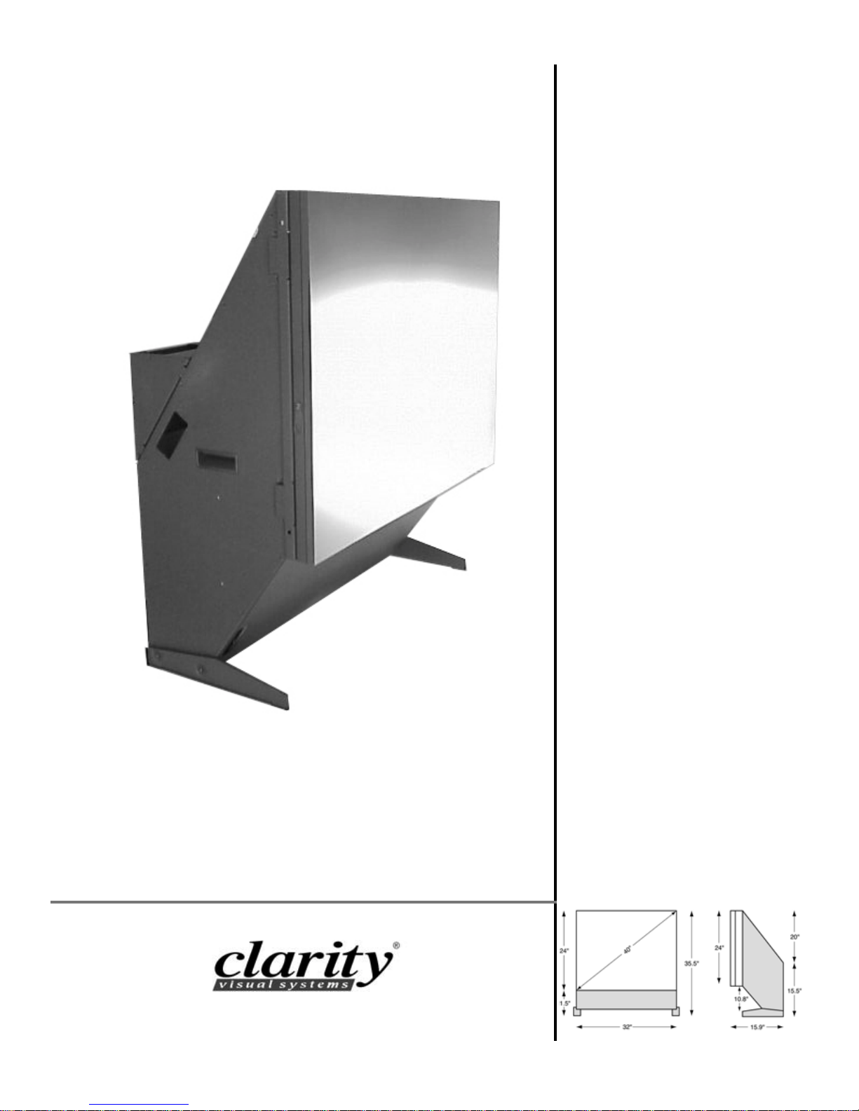
40" Display Wall Unit
Service Guide
070-0050-01
18 April 2003

© 2003 by Clarity Visual Systems™, Inc.
All Rights Reserved.
Contents of this publication may not be reproduced in any form without permission of Clarity Visual Systems,
Inc.
Trademark Credits
Windows™ is a trademark of Microsoft Corp.
Clarity's Big Picture™ is a trademark of Clarity Visual Systems, Inc.
All other names are trademarks or registered trademarks of their respective companies.
Disclaimer:
The information contained in this document is subject to change without notice.
Clarity Visual Systems Company makes no warranty of any kind with regard to this material. While every precaution has been taken in the preparation of this manual, Clarity V isual Syst ems shall not be liable for errors or
omissions contained herein or for incidental or consequential damages in connection with the furnishing, performance, or use of this material.
ii

iii

iv

Table of Contents
1Some Basic Information… 1
1.1 About the WN-4030 … 2
1.2 Your Safety Is Important … 4
1.3 Removing the Screen … 6
1.4 ESD Can Kill Equipment … 8
2 Troubleshooting the Problem … 11
2.1 What Kind of Problem Is It? … 12
2.1.1 Normal Startup Sequence … 14
2.1.2 Startup Problems … 16
2.1.2.1 Using the Remote Control and LEDs … 18
2.1.2.2 How to the Use Menu Chains … 20
2.1.2.3 How to Read On-Screen Status Code … 22
2.1.2.4 How to Read the Inside LEDs … 24
2.1.2.5 How to Read the Status Menu … 26
2.1.2.6 How to Get to the Service Menu … 28
2.1.3 Image Problems … 30
2.1.3.1 Loop-Thru Has Limits … 32
2.1.3.2 How Mode Detect Works … 34
2.1.4 Cooling Problems and Solutions … 36
2.2 Functional Tests in the Field … 38
2.2.1 Is the Picture Acceptable? … 40
2.3 How To Get Technical Support … 42
3 Regular Maintenance … 45
3.1 Changing the Lamp from the Rear … 46
3.2 Replacing the Lamp from the Front … 48
3.2.1 Removing the Optical Engine … 50
3.2.2 Replacing the Optical Engine … 52
3.3 Changing the Air Filter … 54
3.4 Cleaning the Screen and Mirror … 56
4 Taking Apart a Wall … 59
4.1 Removing a Floor-Mounted Display … 60
4.2 Removing a Wall-Mounted Display … 62
5 Replacing Parts … 65
5.1 Where Everything Is … 66
5.2 Replacing the Power Supply … 68
5.3 Replacing the Electronics Module … 70
5.3.1 Installing the Big Picture Key … 72

5.3.2 Installing a Video Decoder Card … 76
5.4 Replacing Parts under the Light Shield … 80
5.4.1 Removing the Optical Engine … 82
5.4.1.1 Replacing the Thermal Cutoff Switch … 84
5.4.1.2 Replacing the Intake Fan … 86
5.4.1.3 Removing the LCD in Optical Engine 750-0605-00 … 88
5.4.1.4 Replacing the LCD in Optical Engine 750-0605-00 … 90
5.4.1.5 Removing the LCD in Optical Engine 750-0605-01 … 92
5.4.1.6 Replacing the LCD in Optical Engine 750-0605-01 … 94
5.4.2 Installing the Optical Engine … 96
5.4.3 Changing the Lamp Ballast … 98
5.4.4 Replacing the Exhaust Fan … 100
5.5 AC Power Entry Repair … 102
6 Reference Section … 105
6.1 Menu Structures, Wildcat S … 106
6.2 Menu Structures, Wildcat SE … 114
6.3 On-Screen Status Codes, Both Wildcats … 124
6.4 LEDs, Wildcat S … 126
6.5 LEDs, Wildcat SE … 128
6.6 Connector Diagrams … 130
6.7 Wiring Diagrams … 132
6.8 Specifications for the WN-4030 … 134
6.10 Technical Support Forms … 140
Index … 143

1 Some Basic Information
1.1 About the WN-4030 … 2
1.2 Your Safety Is Important … 4
1.3 Removing the Screen … 6
1.4 ESD Can Kill Equipment … 8
1

1.1 About the WN-4030
This manual covers both models of the Clarity Wildcat display for troubleshooting and parts replacement. Parts are replaced at the module or “black box” level; there are no component level repairs
required.
The Clarity Wildcat comes in two types:
• WN-4030-S is the standard version. It uses an
800 × 600 LCD, but it also accepts 640 × 480
computer pictures. Optional inputs for C-Video
and S-Video are available, and these connectors
may be in the unit you are servicing. Clarity’s Big
Picture™ is an option that spreads one image over
a wall of displays.
• WN-4030-SE also uses an 800 × 600 LCD, but it
accepts inputs up to 1600 × 1200 and down converts them to 800 × 600.
The two models, called Wildcat S and Wildcat SE,
have somewhat different menus, but in most other
respects they are the same.
Tools required
Fortunately, not many tools are required.
• a #2 Phillips screwdriver
• a flat-blade screwdriver – sometimes even a coin
will do the job for this
• 3/8" socket for the bolts that hold displays
together
•5/16" socket for the nuts that hold cable hole cov-
ers and brackets
Some general information about the WN-4030
• There is no electrical interlock on the screen.
Removing the screen does not turn off the high
voltage, and the lamp stays lit.
• There is an interlock on the lamp access door at
the rear. Opening this door turns off the high voltage and the lamp goes out.
• There is an electrical interlock on the light shield
that covers the optical engine. Removing this
shield turns off the high voltage, and the lamp
goes out.
• There is no electrical interlock on the other rear
access door, the one behind the electronics module.
• The power supply is self-adjusting to 115V or
230V.
not last this long. Median means “middle.” If you
could line up a bunch of lamps in the order they were
going to fail (assuming you could know this in
advance), the lamp in the middle would last 8000
hours.
For the lamps in a WN-4030-SH, the median lamp
life is 4000 hours.
A guide to this manual
This manual is divided into sections and subsections. In general, it is as good idea to read the parent
sections before trying to do something described in a
subsection. For instance, if you want to remove the
“gizmo-thingy,” as described in section 3.2.1.2, first
read sections 3.2 and 3.2.1.
Information about operations and RS232 commands are found in the separate Wildcat S and Wildcat SE manuals, part numbers 070-0046-xx and
070-0082-xx.
Terms used in this manual
The words
•cube
•display
• unit
all mean a single WN-4030 display.
• WN-4030 or “Wildcat” means either type of Wild-
cat.
Lamp Life
The median life of the lamp in a WN-4030-S is
8000 hours. Half of any sample of lamps will last at
least this long. Some lamps, maybe half of them, will
2
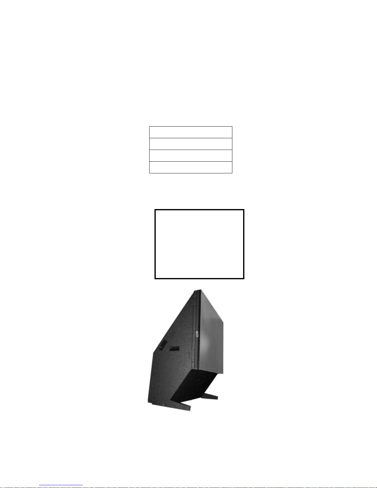
Tools You Will Need
#2 Phillips screwdriver
flat-blade screwdriver
3/8" socket wrench
5/16" socket wrench
In this Service
Guide,
the words, “display,”
“unit,” and “cube”
all mean a WN-4030,
one of these
!
3

1.2 Your Safety Is Important
This list of safety warning and caution notes isn’t very long. Reading it could save you from getting an
electric shock, a UV radiation burn, or a heat burn.
These display units were designed with safety in
mind. However, if you don’t heed the safety warning
and cautions, you could get hurt. The safety warning
are on stickers in various places in and on the display.
they are reproduced on these pages so you can see
them all at once.
There are some other times you should be aware of
that relate to safety, things to keep in mind while
installing and using the displays:
• There is no electrical interlock for the screen.
Removing the screen does not turn off the AC
power or the lamp.
• There is a switch under the light shield.
Removing the light shield turns off high voltage
to the lamp. Do not bypass this switch.
• There is another switch behind the lamp access
door in the rear. Opening this door turns off
high voltage to the lamp. Do not bypass this
switch.
• If the displays are hung on a wall, the wall must
be strong enough to hold them. Each unit
weighs about 68 lbs (31 k g). S imply mounti ng
them into wallboard or wall paneling won’t be
adequate or safe.
• If the displays are standing on the floor, use the
optional base. Secure the bases to the floor and
to each other before stacking displays on them.
Then secure the displays to the base. the base is
not very deep, front to back, and a high stack
could tip over , injuring or even killing someone.
You may not need a base for one row of displays
on the floor, but if the displays will be stacked
two high, use the base. Very high stacks – over
four high – should be tied back to a supporting
wall.
4
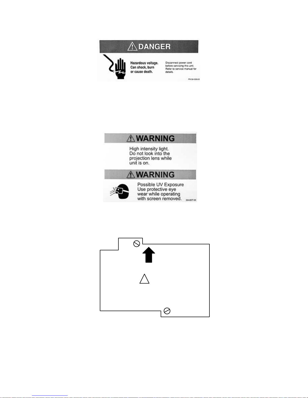
FRONT
!
WARNING
HOT SURFACES NEAR
LAMP. SKIN BURN
HAZARD
Lamp housing label, seen from the rear.
When you see it, this label will appear upside down,
and the arrow will point down.
5
1.3 Removing the Screen
The screen is held on by four spring-loaded clips. When the display is in a wall, insert a thin object
between the screens to bring out the built-in scr een handles. Don't lift the display by the screen. When
you place the displays in a wall, use the external hand grips or the internal struts for lifting.
The screen is held on with four spring-loaded latches,
one near each corner.
To remove the screen from a single display
When it is standing alone, pull out sharply at the
four corners. Y ou only need to pull out about one inch
to release the latch. The display is relatively light (68
lbs.), and four latches together are strong. It may be
necessary to have someone hold the back of the display as you pull forward.
CAUTION
Do not twist the screen as you remove it.
Twisting the screen may break the springloaded latches. Pull straight forward. If one of
the latches still holds a corner, do not twist
the screen to get it loose.fio
To remove the screen from display in a wall
On Wildcats with glass screens, use a suction cup
to pull at the four corners of the glass, one corner at a
time. Pull out sharply just enough to release the
spring latch, about one inch or 25 mm.
On some Wildcats, you can use the built-in tabs.
The tabs are small nylon handles, one on each side of
the screen.
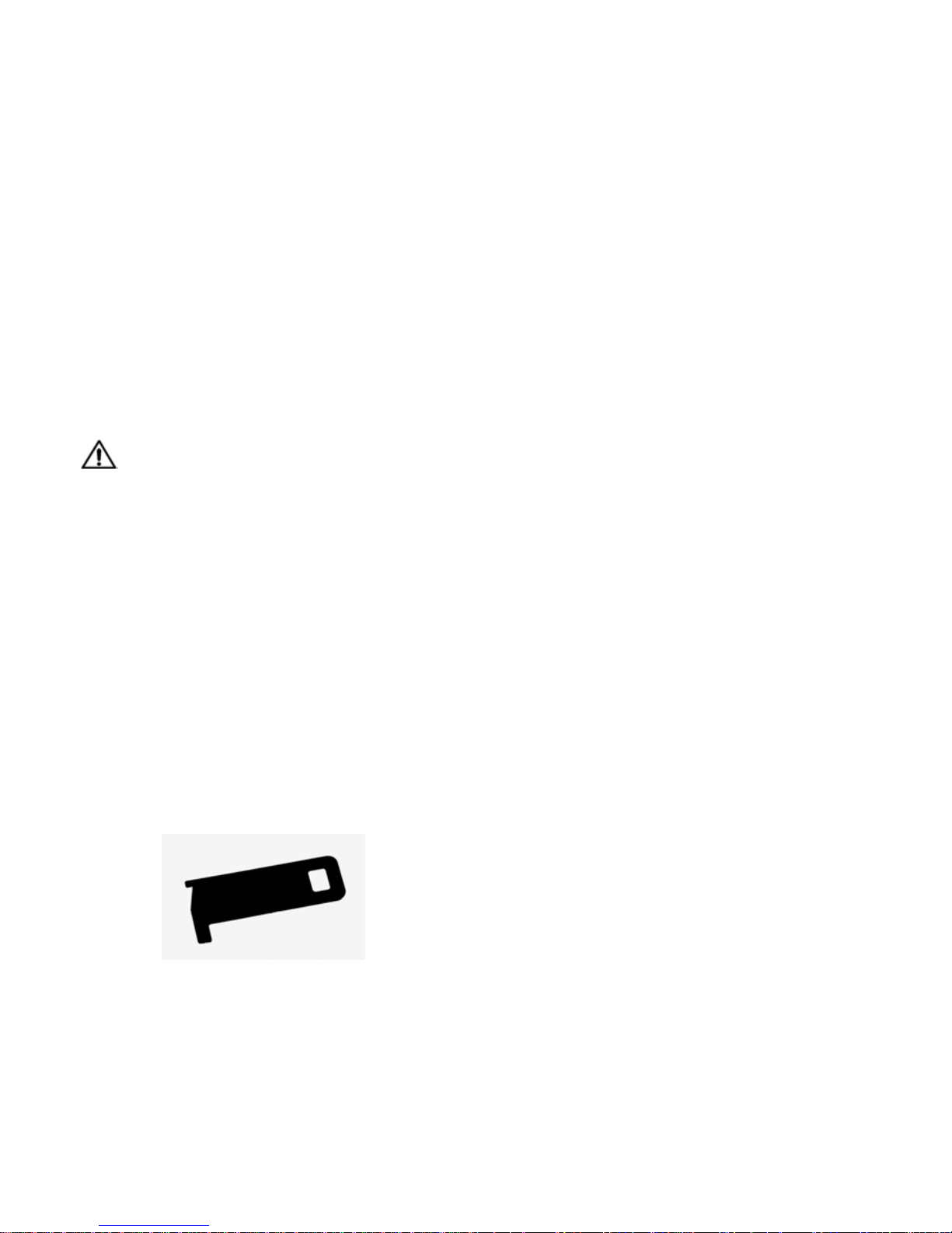
Use the screen puller tool, shown here. Slide the
tool between the screens and hook the tab to retrieve
it. The tab has points to hook or push to get it to turn
out. If you don't have the screen pullers, you can use
anything thin and plastic, such as a credit card.
tool, through the hole in the tab to get a good grip on
it. Be careful not to scratch the screen.
Do not twist the screen as you remove it. If one of
the latches still holds a corner , do not tw ist the screen
to get it loose.
To replace the screen
, line up the screen with the four corners of the
chassis. Use the heel of your hand to press sharply at
each corner, snapping the latches in place.
Screen tethers
Some installations use wire tethers on the screen
for safety. The wires hold the screen on both sides.
You can still remo ve the screen and lower it to work
inside, and usually that is enough.
If you have to remove the screen completely,
remove the tethers from the chassis end and leave the
tethers attached the screens. The tethers loop around
a threaded stud on the chassis. The stud has a nylock
nut. The loop at this end of the tether is large enough
to come off over the nut.
When you replace screens like this, loop the wire
over the stud again, and do not tighten the nut.
Handling the displays
The display has two hand grips, one on each side.
Do not lift the display by the screen.
When the screen is off, you can use the two braces
inside, near the upper corners. These are handy when
lifting displays into a wall.
You need to pull on the correct tabs. There will be
two tabs between each pair of screens. To pull a
screen, use the upper tab on the right side and the
lower tab on the left. Remember: High-right, Lowleft.
Pull sharply forward on the tabs. You may have to
put something, such as a tie-wrap or the screen puller
6
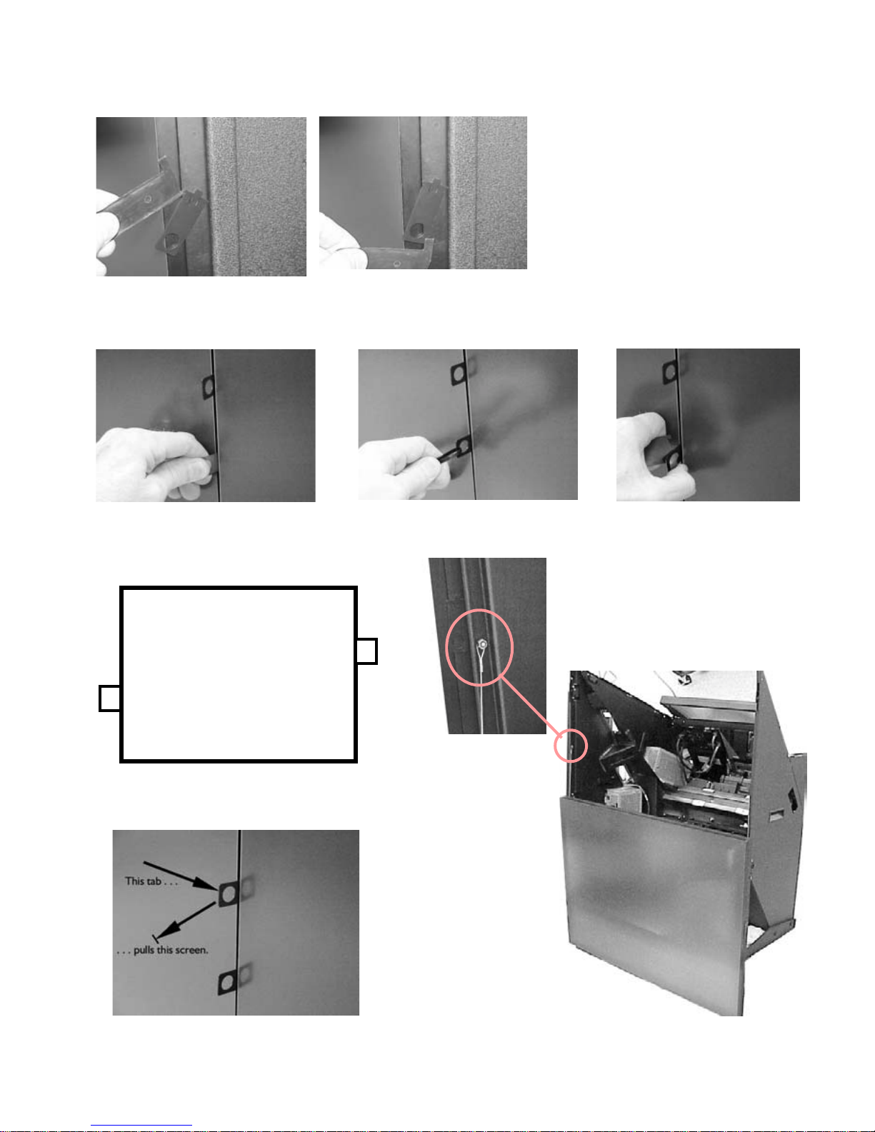
1a. Use screen puller tool to push
the hooks on the tab …
2a. Pull the tab, resting hand against
next screen …
High Right
1b … or hook the tab and pull it out.
b … or pull the tab with a tie-wrap …
2c … or pull the tab with the
screen puller tool.
Screen tethers are looped over a stud on
the inside of the chassis frame.
Do not tighten this nut.
Low Left
When you remove a screen from a wall, use
the High tab on the Right
and the Low tab on the Left.
7

1.4 ESD Can Kill Equipment
ESD – electro-static discharge – can literally kill electronic equipment. The components in the
WN-4030, particularly the electronics module, are very susceptible to ESD. Take precautions by using
an approved grounding strap when handling these parts.
MOS-FETs and J-FETs (two types of field-effect tran-
sistors) are wonderful components in circuits. They
provide high amplification with very little power consumption, but they are extremely vulnerable to static
discharge. These components are used in the modules (electronic boxes) in this product.
Static electricity can easily build up in your body,
and you won’t even know it. Rubber-soled shoes on
vinyl floors, walking across carpet or rugs, even swiveling in your chair can build up enough static electricity to zap (kill) a FET. If you kill the FET, you kill the
module it is in.
To prevent electro-static discharge (ESD)
, use a wrist ground strap whenever you remove
and handle any of these modules:
•the electronics module
•the lamp ballast
•the power supply
Before you remove any module listed above, connect
your wrist strap to the main chassis.
Before you install a new module, connect your wrist
strap to the main chassis.
If you carry the module, connect the wrist strap to a
ground point on the module.
When you pack a module for shipping
, use an anti-static bag, if possible. If you don’t
have an anti-static bag, wrap the module in aluminum foil before packing it.
Never, never
pack the bare module in loose, styrofoam "peanuts." When these styrofoam pieces touch the connectors, they can easily zap a FET.
8

ESD Precautions
for handling electronics modules,
power supplies
and ballasts:
• When you remove an electronic "box," connect a wrist strap
to the main chassis before you start.
• When you walk with an electronic part, always connect a
wrist strap to a ground point (the case) on the part.
• When you ship a part separately, put it in an anti-static bag,
or wrap it in aluminum foil, before packing it in a carton.
• Never put the bare, unwrapped device in an ordinary plastic
bag or styrofoam of any kind.
9

10

2 Troubleshooting the Problem
2.1 What Kind of Problem Is It … 12
2.1.1 Normal Startup Sequence … 14
2.1.2 Startup Problems … 16
2.1.2.1 Using the Remote Control and LEDs … 18
2.1.2.2 How to the Use Menu Chains … 20
2.1.2.3 How to Read On-Screen Status Code … 22
2.1.2.4 How to Read the Inside LEDs … 24
2.1.2.5 How to Read the Status Menu … 26
2.1.2.6 How to Get to the Service Menu … 28
2.1.3 Image Problems … 30
2.1.3.1 Loop-Thru Has Limits … 32
2.1.3.2 How Mode Detect Works … 34
2.1.4 Cooling Problems and Solutions … 36
2.2 Functional Tests in the Field … 38
2.2.1 Is the Picture Acceptable? … 40
2.3 How To Get Technical Support … 42
11

2.1 What Kind of Problem Is It?
Is this a startup problem or an image problem? Usually a black screen means its a startup problem. If
you can see anything at all, it is probably an image problem. This whole chapter divides the types of
problems into smaller and smaller groups, eventually leading you to another section of this manual.
Types of startup problems
Look through this list. If any of these things apply
to your situation, the problem is a startup problem.
• The lamp will not light.
• You can’t display any menus.
• When you press the
gives a triple beep, a very rapid beep-beep-beep.
• When you press the
pens.
• When you press the
flashing, out-of-focus, colored light.
If you see any of the problems above, turn to “Startup
Problems” on page 16.
LAMP ON button, the display
MONITOR button, nothing hap-
MONITOR button, you see a
Types of image problems
If any of these things apply to your situation, the
problem is an image problem.
• The picture is noisy .
• There is a black area on the side or top or bottom
of the screen, and you can’t move the image into
this space with the Position control.
• There is a sign on the screen that says S
A
BSENT.
•You are displaying a computer screen, and you
can’t see enough of the edges.
• The colors seem wrong.
• This display has different colors than the other
display in the wall.
• This display is darker or brighter than the others.
• When you press
of-focus, showing at the bottom of the screen. (No
problem. This is normal.)
• Image is distorted.
• Image is out of focus.
• Lamp is on, but you have no image.
• Image isn’t positioned on the screen properly.
• The lamp lights, but the screen is all white. You
can’t see any picture. When you press the
button on the remote control, no menu appears.
MONITOR, there is a red light, out-
OURCE
MONITOR
12
If you see any of these problems, turn to “Image Problems” on page 30.

13

2.1 What Kind of Problem Is It?
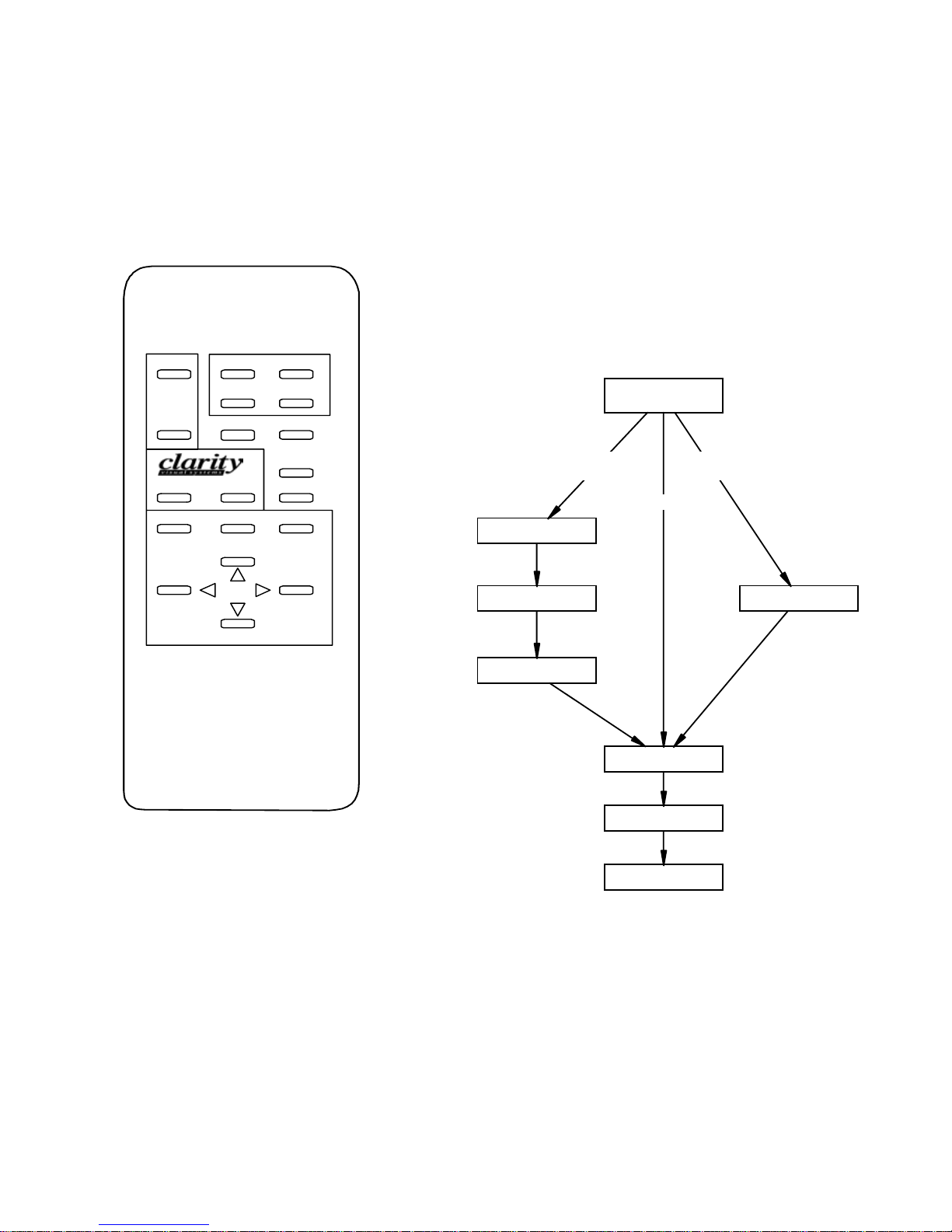
2.1.1 Normal Startup Sequence
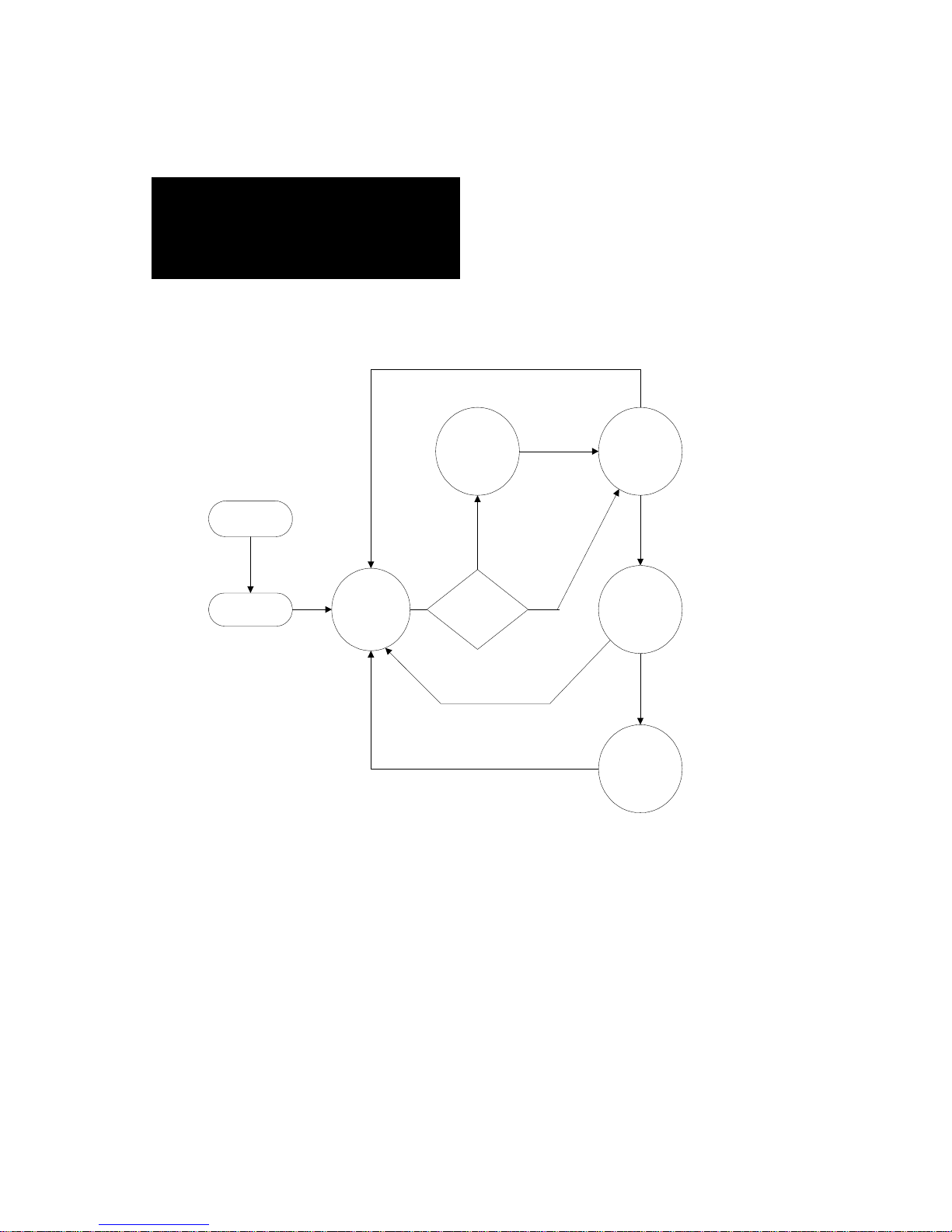
If Auto Lamp On is enabled, the lamp should turn on about one minute after AC power is applied. If
Auto Lamp On is not enabled, about one minute after AC power is applied you can manually turn on
the lamp.
You can observe the startup sequence from the front
or rear . R emove the screen to see it from the fron t and
watch the LEDs on the electronics module. From the
rear, open the right (larger) access door to see the
LEDs.
What happens in the WN-4030:
1. Plug AC power into the power entry box.
2. Turn on the AC switch, which lights up. This
sends AC to the power supply.
3. The power supply sends +5v, –5v and +12v to
the electronics module, the optical engine, and
350V to the lamp ballast.
4. When the electronics module first has voltage, it
goes through an initialization period and takes
care of some housekeeping tasks. It checks the
RS232 port to see if there is any data there. LEDs
turn on and off during initialization.
5. The electronics module turns on the two fans and
goes into a lockout period, for 30 seconds. The
Standby LED flashes. During lockout, you cannot
turn on the lamp. You should see these LEDs:
electronics module is waiting for a lamp on command. This is the standby mode. The fans stop.:
LAMP ON
EXHT FAN
INTK FAN
STANDBY
TEMP
INTRLOCK
SOURCE
RS232 ACT
RS232 CMD
REMOTE
CPU ACT
!!!"""$$$$#
! If Auto Lamp On is checked in the Misc Control menu,
the display goes directly from lockout (Step Step 5.) to
the lamp ignition stage (Step Step 1.). Step Step 1. is
bypassed, and the Standby is never on steady.
1. When the electronics module receives an On
command, or Auto Lamp On is enabled, it enters
the ignition stage.
a) The fans start.
b) The interlock system is monitored to see that
all interlocks are closed.
c) The LCD is energized.
d)The lamp ballast is enabled
LAMP ON
EXHT FAN
INTK FAN
STANDBY
TEMP
INTRLOCK
SOURCE
RS232 ACT
RS232 CMD
REMOTE
!""#""$$$$#
! off
" on
# 1 flash per second
% 2 flashes per second
$ don’t care
1. At the end of lockout, the Standby LED turns on
steady, without flashing, which shows that the
14
! If the either fan is not turning, or if any interlock is open,
the electronics module goes back into the lockout
CPU ACT
period, Step Step 5. above. If a fan is connected but it
isn’t turning, that fan’s LED will flash. If the fan is
completely disconnected, its LED will be off.
2. The lamp ballast applies 25 kV to the lamp which
produces an arc in the lamp. As the gas in the
lamp heats up, it becomes more conductive,
which causes the ballast to decrease the voltage
and increase the current. During this ignition
stage, the Standby LED flashes quickly (2 flashes
per second).
LAMP ON
EXHT FAN
INTK FAN
STANDBY
TEMP
INTRLOCK
SOURCE
RS232 ACT
RS232 CMD
REMOTE
CPU ACT
%""%""$$$$#
1. When the lamp is lit, the ballast sends a signal to
the electronics module, and the Standby LED goes
out. The Lamp LED turns on.
LAMP ON
EXHT FAN
INTK FAN
STANDBY
TEMP
INTRLOCK
SOURCE
RS232 ACT
RS232 CMD
REMOTE
CPU ACT
"""!""$$$$#
Interlock opens
Standby state: Standby
LED is on steadily, no
flashing
AC Power Up
Electronics
initializes itself
Lockout state: Standby LED
is flashing slowily, one flash
per second
Lockout:
30 seconds
Standby
No
Auto Lamp On
Enabled?
Interlock opens
Remote Lamp Off
RS232 POF
Interlock opens
Remote Lamp Off
RS232 POF
RS232 PON
Remote Lamp On
Yes
Lamp Delay, if
any, from Misc
Control menu
Lamp Ignition
Lamp On
Ignition state: Standby LED
is flashing quickly, two
flashes per second
Lamp On state: Standby
LED is off
15

2.1 What Kind of Problem Is It?
2.1.2 Startup Problems
Startup problems usually mean the screen is black – no image, no menus. If the display has power and
the electronics are working, you can learn a lot by watching the LEDs (inside the cube, viewed with
the screen off) or the On-Screen Status Codes (viewed with the screen on).
Follow these steps to determine what the problem is:
1. Press the
Do you see a Monitor Status menu?
a) Yes – This is not a startup problem. Turn to
section “Image Problems” on page 30.
b)No – Go to Step 2..
2. Do you see a colored light in the lower right part
of the screen? It may be flashing or steady. It may
have two colors. It will be out of focus and look
strange.
a) Y es – This light is flashing in a non-secret code.
See “How to Read On-Screen Status Code” on
page 22 to learn how to read the code.
b) No – The electronics module is not operating.
Go to Step 3..
3. Remove the screen. Is the circuit breaker inside
the unit lit?
a) Yes – Go to Step 4..
b) No – Power problems: Check line cord, source
AC power, circuit breaker switch.
4. Are any LEDs lit on the electronics module?
a) Yes – These LEDs will tell you the state of the
display. See section “How to Read the Inside
LEDs” on page 24 to learn w hat th e se LED s
mean.
b)No – Go to Step 5..
5. Is the power supply on the left wall of the cube
connected to the left side of the electronics module?
a) Yes – Either the power supply is dead or the
electronics module is dead. Or both. Swap the
power supply with a known good supply. (See
section “Replacing the Power Supply” on
page 68.) If that does not help, then swap the
electronics module with a known good one. See
section “Replacing the Electronics Module” on
page 70.)
b) No – Turn off AC power. Connect the power
supply to the electronics module. Turn on AC
power again.
MONITOR button on the remote control.
16

17

2.1 What Kind of Problem Is It?
2.1.2 Startup Problems
2.1.2.1 Using the Remote Control and LEDs
The LEDs are inside, but they are duplicated in the Status Menu. If you can’t see the inside LEDs,
there are two bright LEDs that flash a code on the scr een. The r emote control has special buttons that
start menu chains, a series of menus presented in the order you normally use them.
The remote control opens menus on the screen and
gives you control of the electronics. The remote has
many “hot key” buttons that go directly to the control
you want.
Many of the hot keys lead you through a menu
chain, a series of menus presented in a natural order.
Each press of a hot key moves you to the next menu
in the chain.
The menu chains are slightly intelligent;: they take
you through different paths depending on what
choices you make in the menus. These chains are
listed on the facing page and shown as diagrams in
“How to the Use Menu Chains” on page 20.
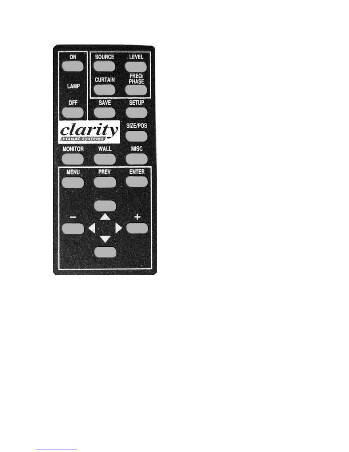
Menu button
Press the
open the Main Menu. The up and down arrow buttons move the selection arrow through the various
items. Press
Many of the Main Menu items have hot keys, so
you can initiate these functions without using the
Main Menu. This is a little faster and more convenient.
The
selection or it moves you to the next menu.
Menu symbols
MENU button on the remote control to
ENTER to choose an item.
ENTER button either activates the current
" is the selection arrow. Move this symbol with
the up and down arrow keys on the remote
control to choose a function. Press
activate the function.
ENTER to
#$ means you can change this item with the + and
– arrow keys.
$ at the right end of a menu item means that
when you press
another menu.
ENTER for this item, it leads to
! is a radio button. Only one of these buttons in a
group can be selected at a time. Use the
button to select one of these radio buttons,
which deselects all the others.
ENTER
" is the currently selected radio button.
& is a check box that is not checked. Select it with
ENTER button. Several check boxes can be
the
selected at one time.
' is a check box that is selected. Its feature is cur-
rently active. Deselect it with the
ENTER key.
# is a selector dot in the Source Select menu
(only). It indicates the current selection.
" is a momentary push button. Press
push it when the selection arrow points to it.
When this button is pushed, it changes shape a
little.
LEDs and Status menu
The WN-4030 has three ways to find out what is
happening: Status menu, inside LEDs, and
On-Screen Status Codes.
Press
MONITOR on the remote control to see the
Status menu. Part of this menu repeats the state of
the inside LEDs. Turn the page to see an explanation
of all the items in this menu.
You can see the inside LEDs if you remove the
screen. You can also see them through the rear access
door. See “How to Read the Inside LEDs” on page 24.
The On-Screen Status Codes help you when the
lamp does not light and you can’t see the inside
LEDs. Press
Codes operate. They flash a simple code in the lower
left part of the screen. See “How to Read On-Screen
Status Code” on page 22.
MONITOR to make the On-Screen Status
ENTER to
18
SETUP button menu chain goes to menu:
Source Select, then
if Source1 or Source2 is selected, then
Frequency/Phase
Black Level
White Level
Color Balance
Position
Save Config
or if Digital is selected, then
Color Balance
Position
Save Config
or if C-Video or is S-Video selected, then
Video Controls
Color Balance
Position
Save Config
LEVEL button menu chain goes to menu:
if the currently selected source is Source1
or Source2, then
Black Level
White Level
Color Balance
or if the currently select source is Digital, then
“Input level controls do not apply to digital
sources”, then
Color Balance
or if the currently selected source is C-Video or
S-Video, then
Video Controls
Color Balance
SOURCE button menu chain goes to menu:
Source Select, then
if Source1 or Source2 is selected, then
Frequency/Phase
Black Level
White Level
Mode Detect
or if Digital is selected, then
Mode Detect
or if C-Video or is S-Video selected, then
Video Controls
Mode Detect
SAVE button menu chain goes to menu:
Save Config
Recall Config
Reset Config
SIZE/POS button menu chain goes to menu:
Position
Zoom Control
19
2.1 What Kind of Problem Is It?
2.1.2 Startup Problems
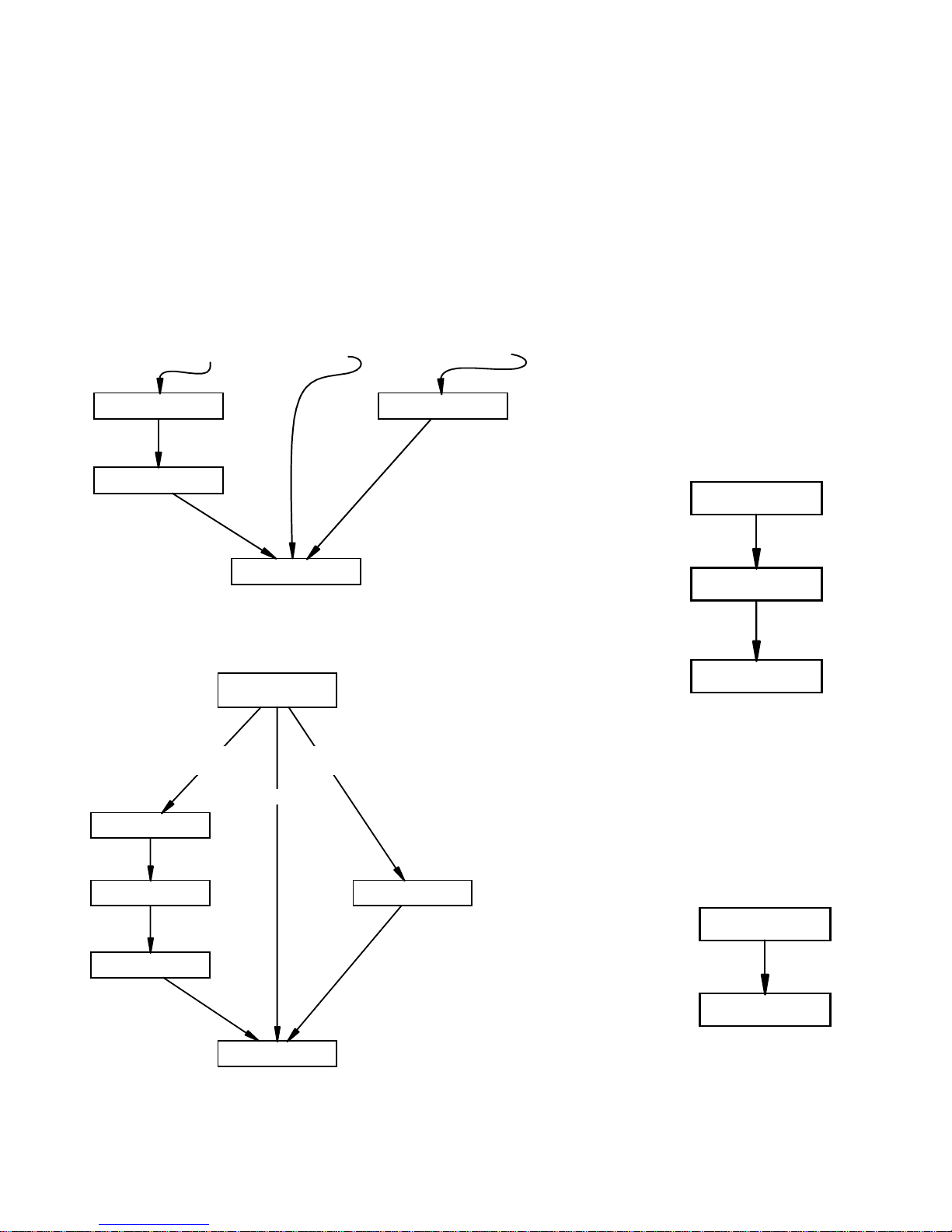
2.1.2.2 How to the Use Menu Chains
The menu chains go through a string of related menus. The diagrams on these pages show how these
strings connect one menu to another . Each push of the designated button steps to the next menu. The
last push exits all menus.
LEVEL button menu chain
If the current source
is Source1 or Source2
Black Level
White Level
OURCE button menu chain
If Source1 or Source2
is selected. . .
If the current
source is Digital
Color Balance
Source Select
If C-Video or S-Video
is selected. . .
If the current source
is C-Video or S-Video
Video Controls
SAVE button menu chain
Save Config
Recall Config
Reset Config
If Digital is selected. . .
Frequency / Phase
Black Level
White Level
Mode Detect
20
SIZE/POS button menu chain
Video Controls
Position
Zoom Control
SETUP button menu chain
LAMP
OFF
+
SOURCEON
CURTAIN
SAVE
WALLMONITOR
PREV M ENUMENU ENTER
LEVE L
FREQ/
PHAS E
SETUP
SIZE/POS
MISC
–
If Source1 or Source2
is selected. . .
Frequency / Phase
Black Level
White Level
Source Select
If C-Video or S-Video
is selected. . .
If Digital is selected. . .
Video Controls
Color Ba lan ce
Remote control
Position
Save Config
21

2.1 What Kind of Problem Is It?
2.1.2 Startup Problems
2.1.2.3 How to Read On-Screen Status Code
If the lamp is not lit, you can still get important information from the display by watching the
On-Screen Status Code. Two, bright LEDs flash behind the screen in a simple code.
The Status Menu is the best place to get information
about the display, and the inside LEDs are next best.
But if the lamp won't light and you don't want to (or
can't) take the screen off, the On-Screen Status Code
will tell you what you need to know.
The On-Screen Status Code are two very bright
LEDs (one red and one green or some other color)
that flash on the back of the screen at the lower right
corner. The flashes form a coded pattern , whic h can
tell you about the system.
To start the On-Screen Status Code
Aim the remote control at the screen and press
monitor. If the lamp is on, this will also display the
Status menu. You should immediately see the LEDs
in the lower right corner of the screen. (If you do not
see these LEDs
This is not a secret code. The table on the facing
page shows the patterns. Read the pattern, then look
in the following list for an explanation.
Exhaust Fan locked—The rotor on the exhaust fan
has stopped. Either some object has stopped it
from rotating, the fan is disconnected, or it has
failed. The lamp will not light until this problem is
fixed.
Intake Fan locked—The rotor on the intake fan has
stopped. Either some object has stopped it from
rotating, the fan is disconnected, or it has failed.
The lamp will not light until this problem is fixed.
Thermal interlock open—The lamp has overheated,
tripping the thermal interlock. This interlock can
be reset, but you should first determine why it
tripped. The lamp will not light until this problem
is fixed.
Lamp door switch open—The lamp door at the rear
is open or not securely closed. The lamp will not
light until this door is closed.
Light shield switch open —The light shield is not
properly in place and not closing the switch. The
lamp will not light until the light shield is properly
in its place.
One or more temps went beyond limit—A t least one
of the three temperature sensors has detected a
temperature over its limit. The lamp may still
light.
Unit is in lockout period—The lockout period is
about 30 seconds long. Every time the lamp goes
off the system goes into this lockout state while
the fans cool the lamp so it can be lit again. This
lockout state also occurs during AC power up. At
this end of this period the display should go into
Standby, below, or the lamp will turn on automatically.
Unit is in Standby—After the lockout state, the sys-
tem goes into Standby and waits for an On command from the remote or from RS232. If the Auto
Lamp On feature in Misc Control is enabled with
an ×, the display goes from Lockout to Lamp On
immediately, unless there is an Interlock open.
Lamp is on—If you see this pattern and you do not
see the Status menu, something is seriously
wrong. The electronics module thinks the lamp is
on, but it isn't. Call a qualified service person.
The Priority rating in the table shows which problems are most important. If there are two problems,
only the pattern with the lower number will show up
in the code. When this problem is fixed, the next
problem will show in the code.
To stop the On-Screen Status Code
Press the monitor button again. The Status menu
goes away.
How the On-Screen Status Code works
The pattern is designed so you can look at the colors or the long-short pattern of the lights. Or both.
The pattern repeats continuously .
The pattern does not change when the status
changes. For instance, if the unit were in Lockout (7)
and you turned on the On-Screen Status Code with
the
MONITOR button, you would see the Red-Amber-
Red code. At the end of the Lockout Period, the unit
would go into Standby Mode (8), but the code would
not change.
If you turn off the codes with the
then turned them back on again, you would see the
Standby Mode pattern of Red-Red Amber.
In other words, when you display the codes, the
electronics module asks just once about the current
status of the unit. This one code is displayed until the
codes are turned off.
MONITOR button,
22
 Loading...