

Page 1
(540) 563-2000
SX15-T, SX15-TM, SX30-T, SX30-8, SX15-8
Issue 10
PAGING HORNS
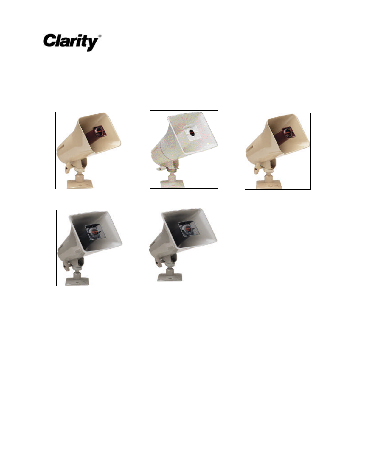
SX15-T
SX30-T
INTRODUCTION
The SX15-T, SX15-TM, SX15-8, SX30-T and SX30-8
are Paging Horns for use with any Clarity
Mixer -Amplifier.
The SX15-T is a 15 Watt horn, the SX15-TM is a 15
Watt horn designed for nautical use and the SX30-T
is a 30 Watt horn, all containing a line matching
transformer. The SX15-8 is a 15 Watt, 8 Ohm paging
horn, the SX30-8 is a 30 Watt, 8 Ohm paging horn.
These horns can be used for interior or exterior
paging applications.
These instructions contain the specifications and
information necessary to install, operate and maintain
the horns.
SX15-TM
SX30-8
SX15-8
SPECIFICATIONS
Product Description
- SX15-T 25/70/100V 15 Watt Paging Horn
- SX15-TM 25/70/100V 15 Watt Paging Horn
(Marine Version - Sealed)
- SX30-T 25/70/100V 30 Watt Paging Horn
- SX15-8 8 Ohm 15 Watt Paging Horn
- SX30-8 8 Ohm 30 Watt Paging Horn
Applications
- Clarity Paging Systems
- Existing 8 Ohm or 25, 70 or 100 Volt Paging
Systems
1 947432
Page 2

Features
- Combination 25/70/100V transformer (SX15-T,
SX30-T, SX15-TM)
- Weather resistant construction
- High im pact plastic housing in beige, gray or
white housing
- Marine version - no fade, white sealed housing
- Fully adjustable 360 degrees horizontal and 90
degrees vertical
- Rotary switch for tap selection
- Stainless steel hardware
- Beam m ount clamp or electrical backbox
Environment
- Temperature: 0 to +50 Degrees C
- Humidity: 0 to 85%
Horn Taps for the SX15-T, SX15-TM
15 Watts, 25/70/100 Volts
Switch Setting
100V 70V 25V Set Ohms
1.9 - - 1 5333
3.8 1.9 - 2 2667
7.5 3.8 - 3 1333
15 7.5 - 4 667
- 15 1.9 5 333
- - 3.8 6 167
- - 7.5 7 83
- - 15 8 42
Horn Taps for the SX30-T
30 Watts, 25/70/100 Volts
Switch Setting
100V 70V 25V Set Ohms
1.9 - - 1 5333
3.8 1.9 - 2 2667
7.5 3.8 - 3 1333
15 7.5 - 4 667
30 15 1.9 5 333
- 30 3.8 6 167
- - 7.5 7 83
- - 15 8 42
- - 30 9 21
Specifications
Frequency Response and Maximum Power
Handling Capability
SX15-T 300 - 10K 15 Watts
SX15-TM 300 - 10K 15 Watts
SX15-8 300 - 10K 15 Watts
SX30-T 300 - 10K 30 Watts
SX30-8 300 - 10K 30 Watts
SPL @ 4 feet at 1 Watt at 1K
SX15-T 105dB
SX15-TM 105dB
SX15-8 105dB
SX30-T 107dB
SX30-8 107dB
Line Voltage
• 25/70/100V (SX15-T, SX15-TM, SX30-T)
• 8 Ohms (SX15-8, SX30-8)
INSTALLATION
Cabling
Standard two conductor shielded cable (18-20AWG)
can be used for connections.
Connections
Connect station or other suitable wire to leads as
follows:
Page Out .......................................Tip
Control Common...........................Ring
Unit
Attaching Speaker to Base
NOTE: For ease of installation, the base can be
attached to the speaker before or after the base is
mounted.
• Loosen position adjustment knob.
• Insert the ball of the base into the socket of the
speaker.
• Tighten the position adjustment knob.
Mounting/Positioning
Mount the horn to a suitable surface using the
hardware provided. These units can be m ounted to a
wall, a beam or an electrical box.
• Mount the base to a wall using the two holes
provided. Knockout holes are provided for
punch out should additional holes be required.
• A "C" clamp is provided with the horns to allow
mounting to a beam. Place the bolt through the
hole in the bottom of the base to secure the "C"
clamp to the beam (See Figure 1).
2
Page 3

• Connection to an electrical backbox is
accomplished by channeling wire through the
ball of the base (See Figure 2) and making
appropriate connections. The base has holes
punched for a double-gang square box, but by
punching out additional knockout holes, the base
can be mounted to a single-gang or octagon box.
The horns may be rotated or moved up and down to
obtain the desired position by loosening the knob at
the bottom of the unit, approximately 1 turn. Make
required adjustments and re-tighten knob.
TECHNICAL ASSISTANCE
When trouble is reported, verify there are no broken
connections leading to the unit.
Assistance in troubleshooting is available from the
factory. When calling, you should have a VOM
available and be calling from the job site. Call
(540) 563-2000 and ask for Technical Support or (540)
767-1555 for Clarity 24-hour Faxback System. Visit our
website at http://www.clarity-com.com
Clarity equipment is not field repairable. Clarity
maintains service facilities in Roanoke, VA. Should
repairs be necessary, attach a tag to the unit clearly
stating your company name, address, phone number,
contact person and the nature of the problem. Send
the unit to:
Clarity
Repair and Return Dept.
5614 Hollins Road
Roanoke, VA 24019-5056
LIMITED WARRANTY
Clarity warrants its products to be free from defects in materials and workmanship under conditions of normal use and service
for a period of one year from the date of shipment. The obligation under this warranty shall be limited to the replacement, repair
or refund of any such defective device within the warranty period, provided that:
1. inspection by Clarity indicates the validity of the claim;
2. the defect is not the result of damage, misuse or negligence after the original shipment;
3. the product has not been in any way repaired by others and that factory sealed units are unopened (A service charge
plus parts and labor will be applied to units defaced or physically damaged);
4. freight charges for the return of products to Clarity are prepaid;
5. all units “out of warranty” are subject to a service charge. The service charge will cover minor repairs (Major repairs will
be subject to additional charges for parts and labor).
This warranty is in lieu of and excludes all other warranties, expressed or implied, and in no event shall Clarity
be liable for any anticipated profits, consequential damages, loss of time or other losses incurred by the buyer
in connection with the purchase, operation or use of the product.
This warranty specifically excludes damage incurred in shipment. In the event a product is received in damaged condition, the
carrier should be notified immediately. Claims for such damage should be filed with the carrier involved in accordance with the
F.O.B. point.
3
Page 4
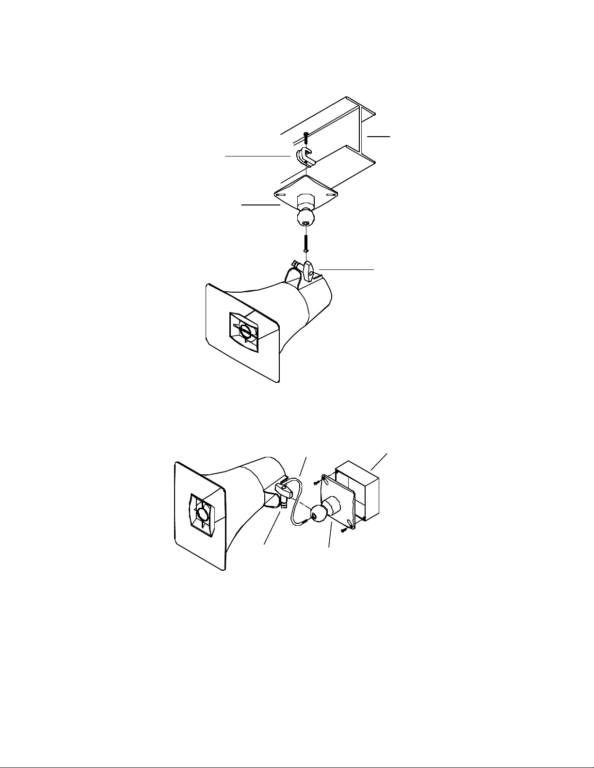
"C" Clamp
Speaker Base
Figure 1 - Mounting to a Beam with a "C" Clamp
I-Beam
Position
Adjustment
Knob
Electrical
Backbox
Position
Adjustment
Knob
Wire
Speaker
Base
Figure 2 - Mounting to an Electrical Backbox
4
 Loading...