

Page 1
Bay Cat X
SN-4620-1080
User Guide
Page 2

2
Page 3

SN-4620-1080
Bay Cat X
46" Direct-view LCD Panel
User Guide
070-0150-00
31 May 2005
Page 4

©2005 by Clarity Visual Systems™, Inc.
All Rights Reserved.
Contents of this publication may not be reproduced in any form without permission of Clarity Visual Systems, Inc.
Trademark Credits
Windows™ is a trademark of Microsoft Corp.
Clarity's Big Picture™ is a trademark of Clarity Visual Systems, Inc.
APLCD® is a registered trademark Clarity Visual Systems, Inc.
All other names are trademarks or registered trademarks of their respective companies.
Disclaimer:
The information contained in this document is subject to change without notice.
Clarity Visual Systems Company makes no warranty of any kind with regard to this material. While every precaution has
been taken in the preparation of this manual, Clarity Visual Systems shall not be liable for errors or omissions contained
herein or for incidental or consequential damages in connection with the furnishing, performance, or use of this material.
LIMITED WARRANTY. Clarity warrants to Buyer that the SN-4620-1080 (the “Product”), if properly used and ser-
viced, will perform substantially in accordance with the product data sheet and users manual, and will be free from defects in
material and workmanship for one year following date of shipment. This warranty does not apply to air filters and other consumable parts.
Improper use is defined as displaying fixed images continuously for long periods of time, resulting in temporary image
retention. Improper use or operation contrary to instructions and specifications contained in the users manual is not covered
by the warranty.
If any Product fails to conform to the written warranty, Clarity's exclusive liability and Buyer's exclusive remedy will be,
at Clarity's option, to repair, replace or credit Buyer's account with an amount equal to the price paid for any such defective
Product returned by Buyer during the warranty period, provided that: (a) Buyer promptly notifies Clarity in writing that such
Product failed to conform, furnishes an explanation of any alleged deficiency and obtains from Clarity a return authorization;
and (b) Clarity is satisfied that claimed deficiencies actually exist and were not caused by accident, misuse, neglect, alteration, improper installation, repair or improper testing. Clarity will have a reasonable time to make repairs, to replace Products or to credit Buyer's account.
LIMITATIONS. Any written warranty offered by Clarity is in lieu of all other warranties, express or implied. Clarity nei-
ther assumes nor authorizes any other person to assume any other liabilities in connection with the sales or use of any product without limitation. Clarity disclaims all other warranties, express or implied, including any warranty of merchantability
or fitness for a particular purpose.
In no event will Clarity be liable to buyer or any other party for procurement costs, loss of profits, loss of use, or for any
other incidental, consequential, indirect or special damages or for contribution or indemnity claims, however caused. Clarity's liability shall be limited to actual direct damages not in excess of the amounts paid to clarity by buyer for the product.
These limitations will apply to all claims, including, without limitation, warranty, contract, indemnity, tort (including negligence), strict liability or otherwise.
ii
Page 5

Table of Contents
Introduction 1
1.1 What are the Main Features of Bay Cat X? … 2
1.2 You Should Have These Accessories … 3
1.3 Safety for You and Bay Cat X … 4
Installing 5
2.1 Installing the DVI Board or SDI Board … 6
2.2 Installing the Bay Cat X Wall Bracket … 9
2.3 Hanging the Bay Cat X on the Wall Bracket … 10
2.4 Connecting Power … 12
2.5 Connecting Picture Sources … 14
2.6 Connecting RS232 Communication … 16
Configuring Bay Cat X 19
3.1 Quick Start … 20
3.2 Setting up a Bay Cat X … 22
3.2.1 Selecting the Picture … 23
3.2.2 Adjusting Levels for Digital Computer Sources … 26
3.2.3 Adjusting Levels for Analog Computer Sources … 28
3.2.4 Adjusting Levels for Video Sources … 30
3.2.5 Aspect Ratio and Scale Mode … 32
3.2.6 Adjusting Sharpness … 35
3.2.7 Position … 36
3.3 Tiling a Display … 38
3.4 Saving Your Work & Recalling a Memory … 40
3.4.1 Memory: What Is Saved? And Where? … 42
3.4.2 Scaling and Cropping … 44
3.4.3 Adjusting Color Balance … 46
3.4.4 Zoom and Position … 49
3.4.5 Viewport Adjustment … 51
3.5 Advanced Options … 52
3.5.1 Miscellaneous Options … 56
3.5.2 Backlight Control … 58
i
Page 6

3.5.3 Serial Port Settings … 60
3.6 Other Operations … 63
Maintenance 65
4.1 Cleaning the Screen … 66
Troubleshooting 67
5.1 Basic Bay Cat X Troubleshooting Steps … 68
5.2 Diagnostics, Test Patterns … 70
Reference 73
6.1 Menu Structures … 74
6.2 Remote Control Buttons … 106
6.3 Drawings … 112
6.4 Connector Locations and Diagrams … 114
6.5 Optimizing Your Clarity Display … 116
6.6 EDID: What It Is and How It Works … 118
Glossary of Terms 121
Specifications for Bay Cat X 125
Regulatory Information 127
Index 129
ii
Page 7

1 Introduction
1.1 What are the Main Features of Bobcat X? … 2
1.2 You Should Have These Accessories … 3
1.3 Safety for You and Bobcat X … 4
1
Page 8

1.1 What are the Main Features of Bay Cat X?
Flat screen, long backlight (lamp) life (60,000 hours). Portrait or Landscape orientation
Bay Cat X is a 46" LCD display that can be wall-mounted
or mounted on a stand. The display can be portrait or landscape.
Landscape
Bay Cat X is only 3.96" deep. Its aspect ratio is 1.77
(16:9). Its native resolution is HD (1920 × 1080). It accepts
a wide range of input pictures from VGA to UXGA in
either analog or digital (DVI).
For video it accepts NTSC, PAL, and SECAM as composite, component, or S-Video.
Most important, it is easy to set up and adjust.
What features were added to Bay Cat X?
Bay Cat X (SN-4620-1080) was developed from
Bay Cat (SN-4610-1080), and adds these features and
enhancements.
Portrait
• Native WXGA resolution
• Can be ordered in three different configurations: Base
Model, Video Model, and Broadcast Model
• Automatic ambient light sensing and backlight adjustment
• 40 memory slots for easy configuration switching
• Improved video performance
• Logo capture for custom splash screen
• Improved component servicability
• Integrated Big Picture Option
• Optional tabletop feet
2
Page 9
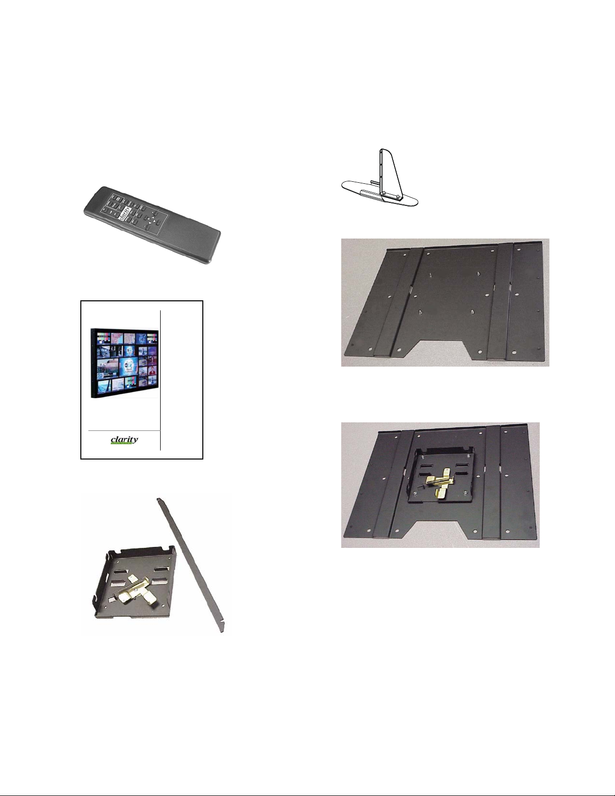
1.2 You Should Have These Accessories
Standard accessories
•1 Power cord
• 1 VGA cable
• 1 Remote control
a
• This User Guide
User Guide
Optional accessories
• Free-standing feet
• Adapter Plate, WAL-4025-00, with hardware
Bobcat X
SN-4045-WX
The Adapter Plate comes with 4 nuts and 8 metric
screws. The 4 nuts hold the Wall Bracket to the Adapter
Plate.
• Wall Bracket, with CATLOCK™ and locking tool
The Adapter Plate can be bolted to a wall. Or the
Adapter Plate can be screwed onto an NEC plasma monitor
display stand using the 8 metric screws.
3
Page 10
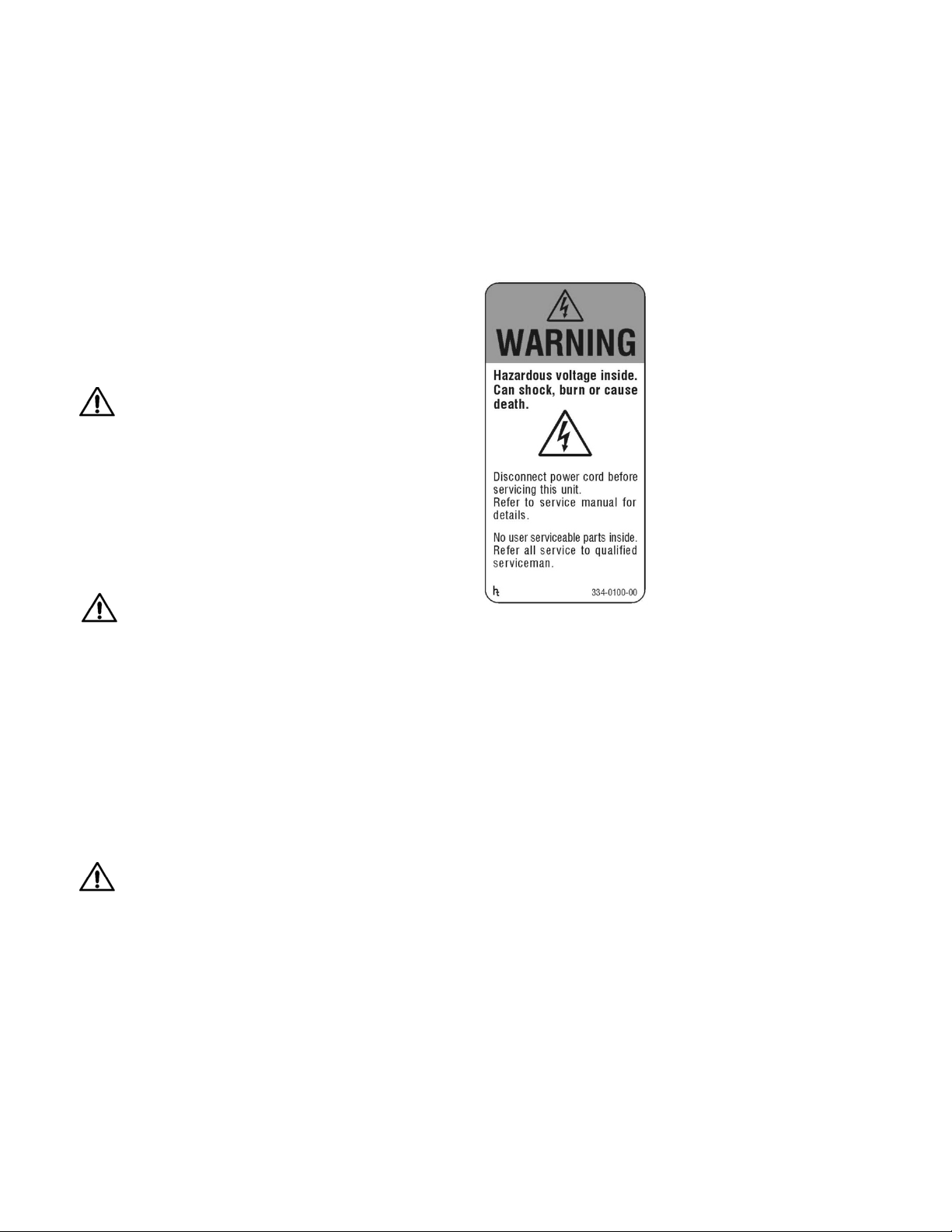
1.3 Safety for You and Bay Cat X
This list of safety warning and caution notes isn’t very long. Reading it could save you from getting an electric
shock.
This display was designed with safety in mind. However, if you don’t heed the safety warning and cautions, you
could get hurt. The safety warning are on stickers in various
places in and on the display. They are reproduced on these
pages so you can see them all at once.
There are some other times you should know relating to
safety:
WARNING
Wall mount s must be secure.
If the displays are hung on a wall, the wall must be
strong enough to hold them. Each display unit weighs
about 73 lbs. (33 kg). Simply mounting it to wallboard or
wall paneling won’t be adequate or safe. The mounting
method must be capable of holding 5 times this weight, 275
lbs. (125 kg) for each display unit.
CAUTION
The screen could be damaged by heavy pressure.
lamp). Follow local ordinances and regulations for disposal.
Bay Cat X screens are protected with a cover glass to
protect the LCD.
Some Bay Cat Xs are shipped, at customer request,
without this protective glass. In these, the LCD is not protected. Slight pressure on the LCD will cause distortion of
the image. Heavier pressure will cause permanent damage.
Bay Cat Xs of this type should be mounted where viewers
cannot touch the screen.
WARNING
The backlight contains mercury.
The backlight is 24 mercury vapor fluorescent lamps.
These cold cathode fluorescent lamps behind the LCD
panel contain a small amount of mercury (112 mg in each
4
Page 11

2 Installing
2.1 Installing the DVI Board or SDI Board … 6
2.2 Installing the Bay Cat X Wall Bracket … 9
2.3 Hanging the Bay Cat X on the Wall Bracket … 10
2.4 Connecting Power … 12
2.5 Connecting Picture Sources … 14
2.6 Connecting RS232 Communication … 16
5
Page 12
2.1 Installing the DVI Board or SDI Board
Clarity Visual Systems ships the DVI or SDI board separately from the Bay Cat X to some customers and for field
upgrades.
✎
The DVI Board is the field-installed video board for
the Video Model of Bay Cat X. The SDI Board is
the field-installed video board for the Broadcast
Model of Bay Cat X.
1. If you powered up the unit to confirm proper working
order upon receipt, turn off AC power to the Bay Cat X
and remove the power cord.
2. Place the unit face down on a flat surface on something
soft and non-scratching. If your unit does not have a
protective face glass panel, be EXTREMELY careful as
the LCD material can be scratched.
3. Confirm that your DVI Board package contains four (4)
mounting screws (SDI Board package contains six[6]
srcews), a replacement DVI or SDI cover panel, and a
disposable grounding wrist strap.
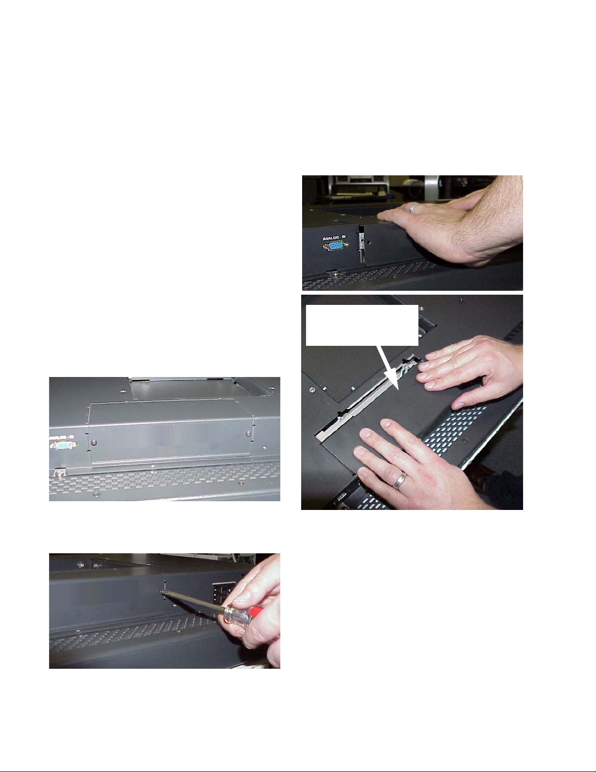
4. On the back of the Bay Cat X, remove the blank cover
panel.
b) Remove the blank panel by pushing down slightly
on the inserted end of the panel as you pull it out.
As you remove the panel,
push down slightly on this
end of the panel as you pull
it towards you
a) Unscrew the two screws holding the blank panel in
place. Save the screws for the replacement panel you
will install later.
6
c) Recycle the blank panel with other aluminum scrap
metal.
5. Attach the grounding wrist strap to bare metal on the
chassis. Using standard ESD procedures, remove the
Page 13
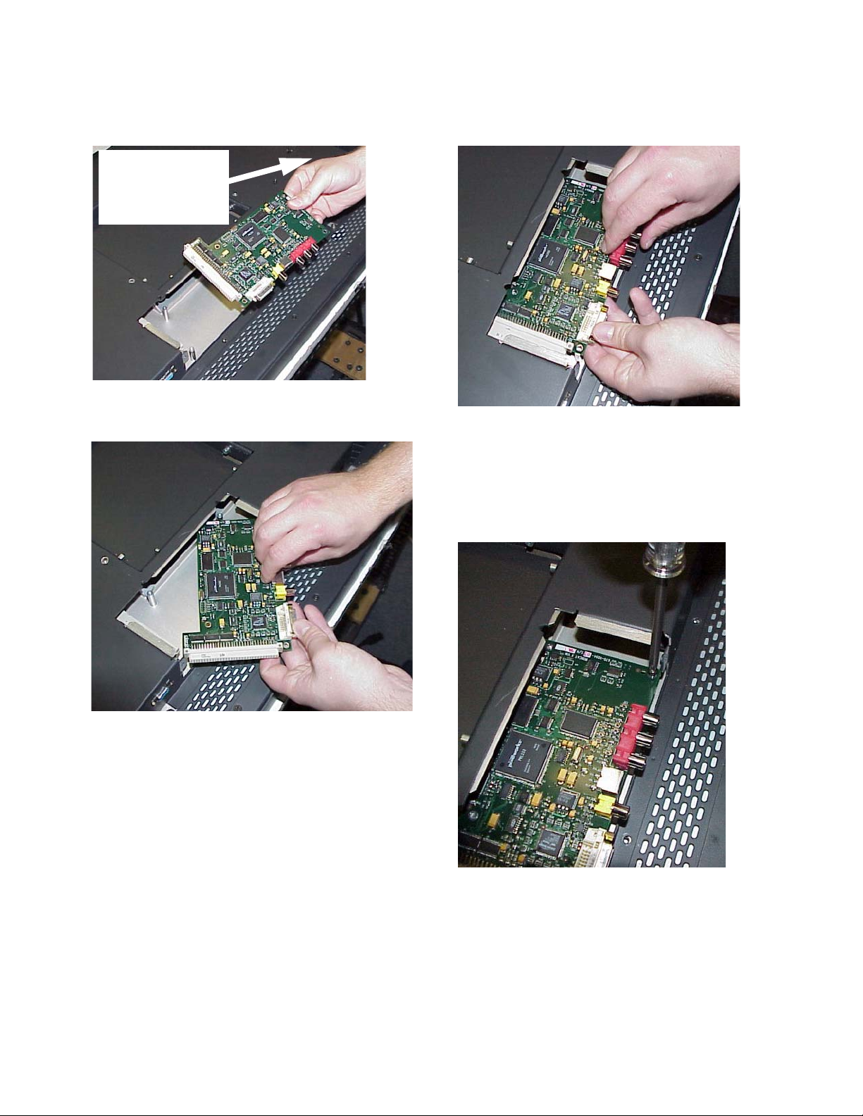
DVI or SDI board from the anti-static bag. (The DVI
board is shown in the pictures below.)
Use a grounding wrist
strap (not shown) or
other personal ESD
devices to prevent
damage to the board
6. Carefully slide the right side of the board into the slot
on the right side of the opening.
7. Align the connector on the board with the connector in
the opening.
Gently push the board into the connector. The board is
fully seated when the four screw holes (six for the SDI
board) are aligned.
8. Screw down the four corners of the DVI board (six
screws for the SDI board) with the supplied mounting
screws.
7
Page 14
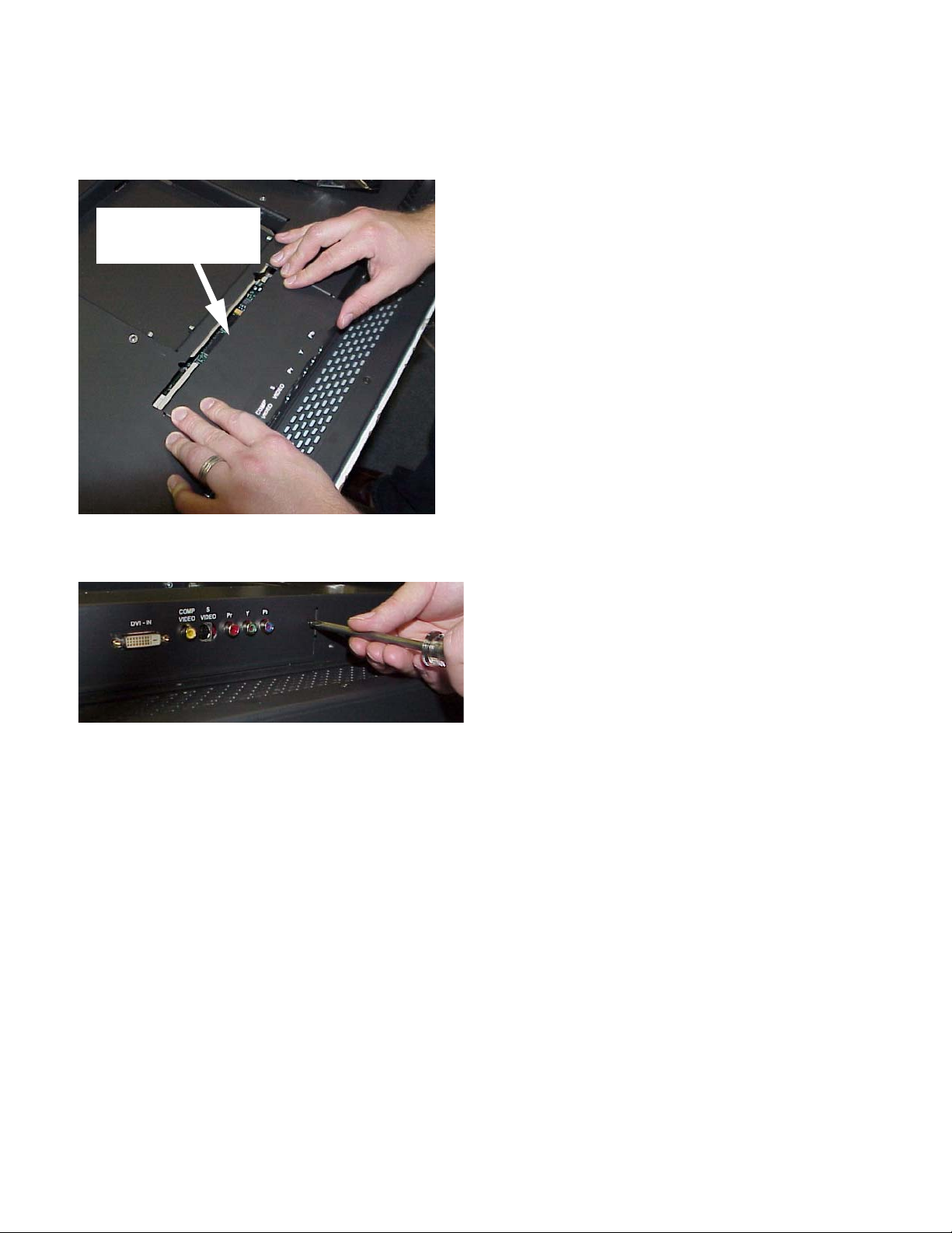
9. Slide the DVI or SDI replacement cover panel into
place. Press down gently on the insertion end of the
panel to help the tabs insert in the slots.
As you insert the panel,
push down slightly on this
end of the panel
10. Secure the DVI or SDI replacement cover panel using
the screws you removed earlier.
8
Page 15
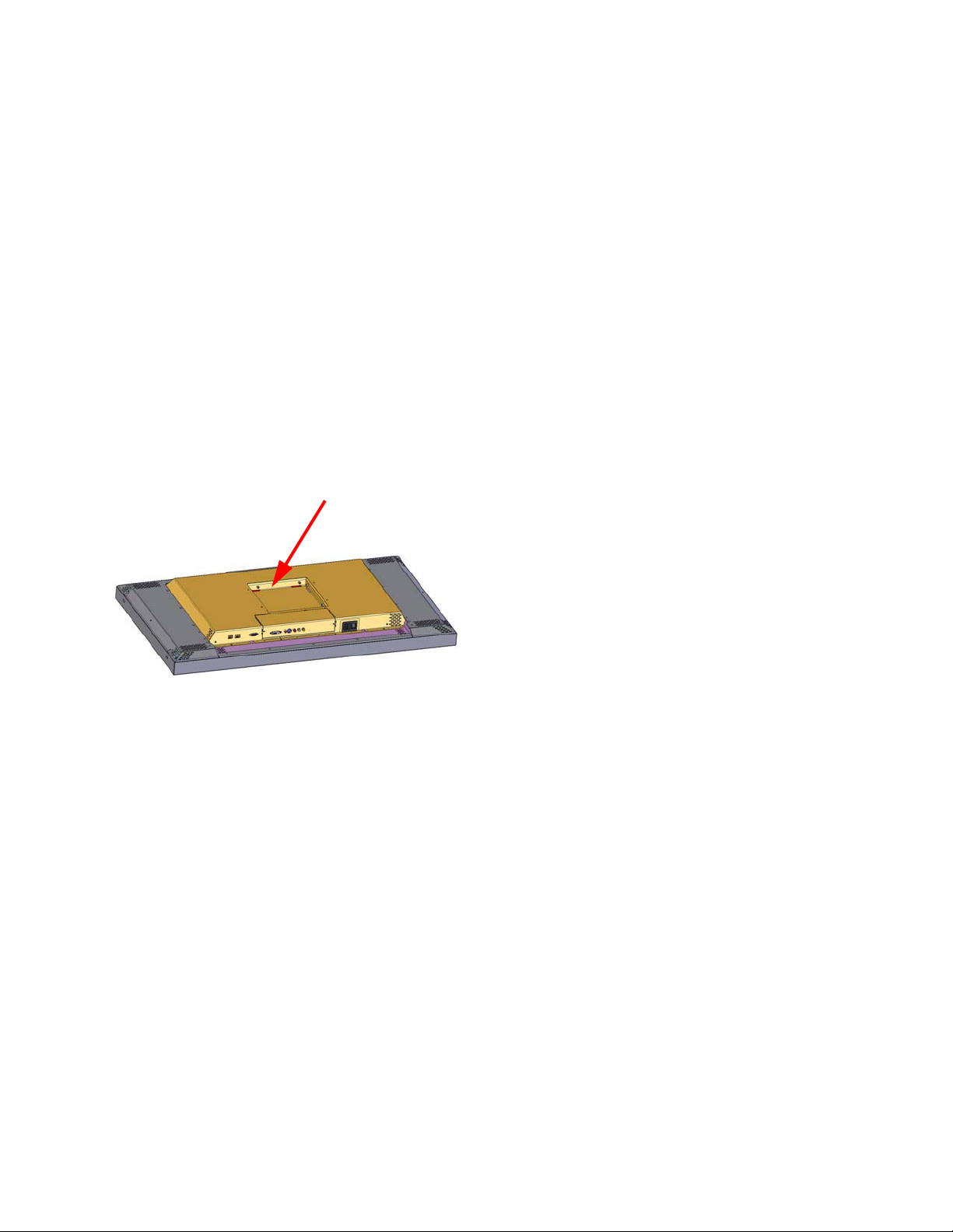
2.2 Installing the Bay Cat X Wall Bracket
The Bay Cat X hangs on its wall bracket in either landscape or portrait orientation.
Installing the wall bracket
The wall bracket comes with each Bay Cat X. See pic-
ture in “You Should Have These Accessories” on page 3.
Using hardware you supply, bolt or screw the wall
bracket to a wall. Be sure to bolt or screw to structural elements of the wall, not just the wall board or drywall. The
Bay Cat X weighs 73 lbs. (33 kg). The mounting method
you use must be capable of holding five times this weight
(356 lbs., 160 kg). The mounting holes are on 6.26" centers. When installed, the wall bracket protrudes 0.375" from
the back panel of the Bay Cat X.
✎ This space at the rear of the Bay Cat X will
be occupied by the wall bracket when the
display is hanging on a wall.
For array mounting guidelines, contact
Clarity Visual Systems.
Ventilation
The Bay Cat X needs no space to the rear for ventilation.
However, like all electronic devices, it does produce some
heat. The space above the display should provide enough
space so that heated air can get away. This means you
should not mount it into a sealed space with nowhere for
the heated air to escape.
Portrait or Landscape
The wall bracket always mounts the same way, whether
the displays will be hung as portrait or landscape. The
hooks on the wall bracket should always have the open part
facing upward.
✎ The Locking Wall Bracket does not have the
large back plate. It consists of the square, open
box with the locking mechanism. This Locking
Wall Bracket with CATLOCK™ is a standard
accessory.
9
Page 16
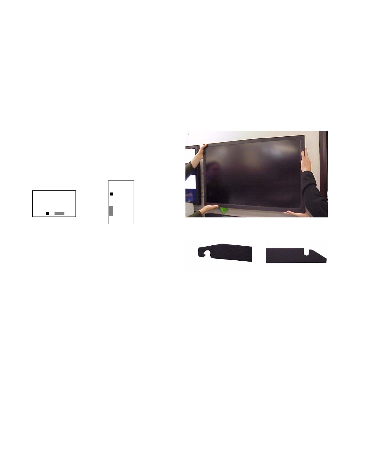
2.3 Hanging the Bay Cat X on the Wall Bracket
The locking system for the Bay Cat X wall bracket prevents the display from jumping off the bracket during earth
tremors, and it helps deter theft.
Two-person job
The Bay Cat X weighs just over 73 lbs. (33 kg). Always
have two persons hang the display on the wall bracket.
Two orientations
The Bay Cat X hangs in either landscape or portrait orientation. The small black square shows the position of the
AC power receptacle. The gray rectangle shows the position of the picture connectors, when viewed from the front.
Landscape
Portrait
✎ The Bay Cat X will not rotate the picture. The
source (computer or video source) must rotate the
picture. The Bay Cat X can rotate the menus, so
the internal menus will be upright with either
orientation.
Hanging the display
Before you hang the first display, practice using the lock
lever to open and close the locking mechanism.
4. Use the locking tool to lock the display onto the wall
bracket. To see if it is locked in place, try to lift the display. If it won’t lift, its locked.
Locking and unlocking
This end of the locking tool
works from below the wall
bracket.
This end of the locking tool
works from the sides of the
wall bracket.
✎ After the display is hung, the connectors for video
and power are a little difficult to see. Some
installers connect power and video cables just
before hanging the display.
1. Be sure the locking lever is in the open position. The
tab on the lever should not protrude below the bottom
of the box.
2. Using two persons, lift the display so the power receptacle is at the bottom for landscape hanging.
✎ For portrait orientation, the power receptacle will
be on the left, looking from the front.
3. Hang the display in the hooks. Pull forward on the display to see that it is properly in the hooks.
10
Page 17
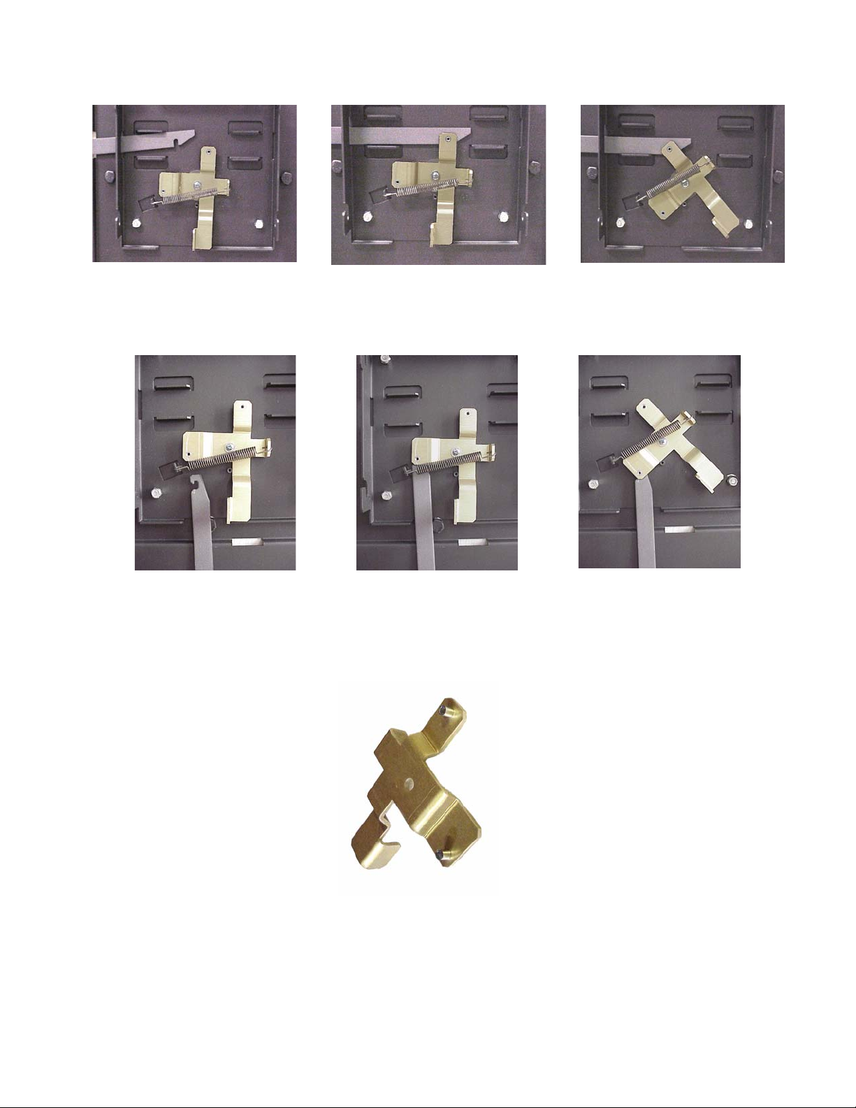
Unlocking from the si de: Slide the tool in from the side. It will ride up
over the lock and catch it. Pull the lock back to unlock.
Unlocking from the bottom: Slide the tool in from the bottom, keeping the open side of the hook to the left, as shown. Catch the lock and
pull down.
Back side of the locking lever, showing the
two pins that the tool hooks onto.
11
Page 18
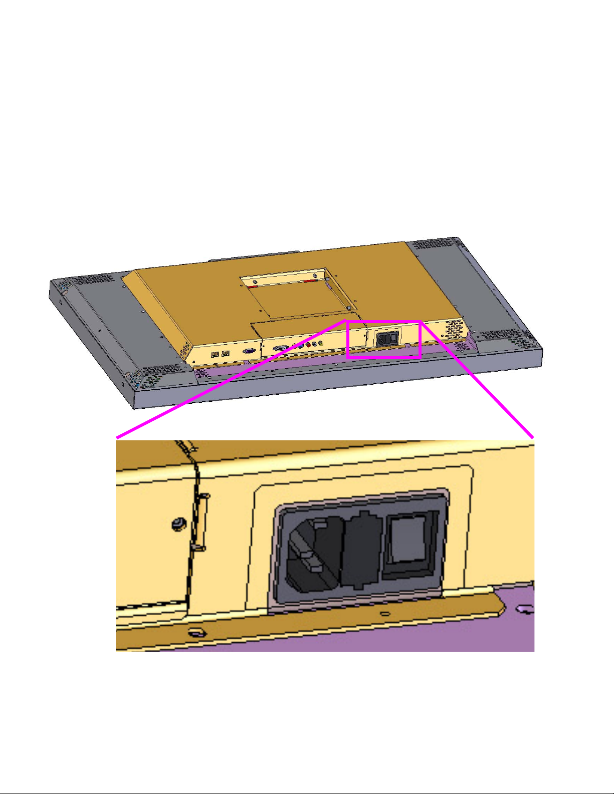
2.4 Connecting Power
Bay Cat X accepts 110-120 VAC and 200-240 VAC with no manual switching.
Plug the power cord into the receptacle on the rear of the
Bay Cat X. Plug the other end into a good source of AC
power.
When ready, turn on the power switch.
Power receptacle and power switch location
Normal operation
It is normal to leave the power connected and the power
switch on all the time and turn the backlight on and off as
desired.
For power receptacle dimensions, see “Connector Locations and Diagrams” on page 114.
12
Page 19

13
Page 20

2.5 Connecting Picture Sources
The Bay Cat X accepts inputs from many different sources, depending on configuration
Which Configuration Do You Have?
The Bay Cat X can be ordered in one of three configurations: Base Model, Video Model, or Broadcast Model. The
Video Model and Broadcast Model have similar input
ports, which are described below.
Base Model Inputs
The base model has one analog computer video input
port and two RS-232 ports (input and output). You may
connect standard sources ranging from VGA to UXGA and
480i, 480p, 720p, or 1080i to the analog video input port.
Video Model and Broadcast Model Inputs
The Video Model and Broadcast Model each have a total
of five different video inputs. Of these five, four are the
same for both models: Analog, Composite, S-Video, and
Component (YPbPr).
The fifth connector on the Video Model is a DVI input
port that accepts all video and graphics signal inputs up to
165MHz pixel clock.
The fifth connector on the Broadcast Model is an HDSDI (Serial Digital Interface) input port, which accepts all
video inputs.
YPbPr sources
Component video sources, such as those provided by
some DVD players, should be connected to the component
connectors. These connectors accept 480i and 576i signals
(480p and HD signals are not accepted).
Most DVD players have red, green, and blue RCA con-
nectors for component video output.
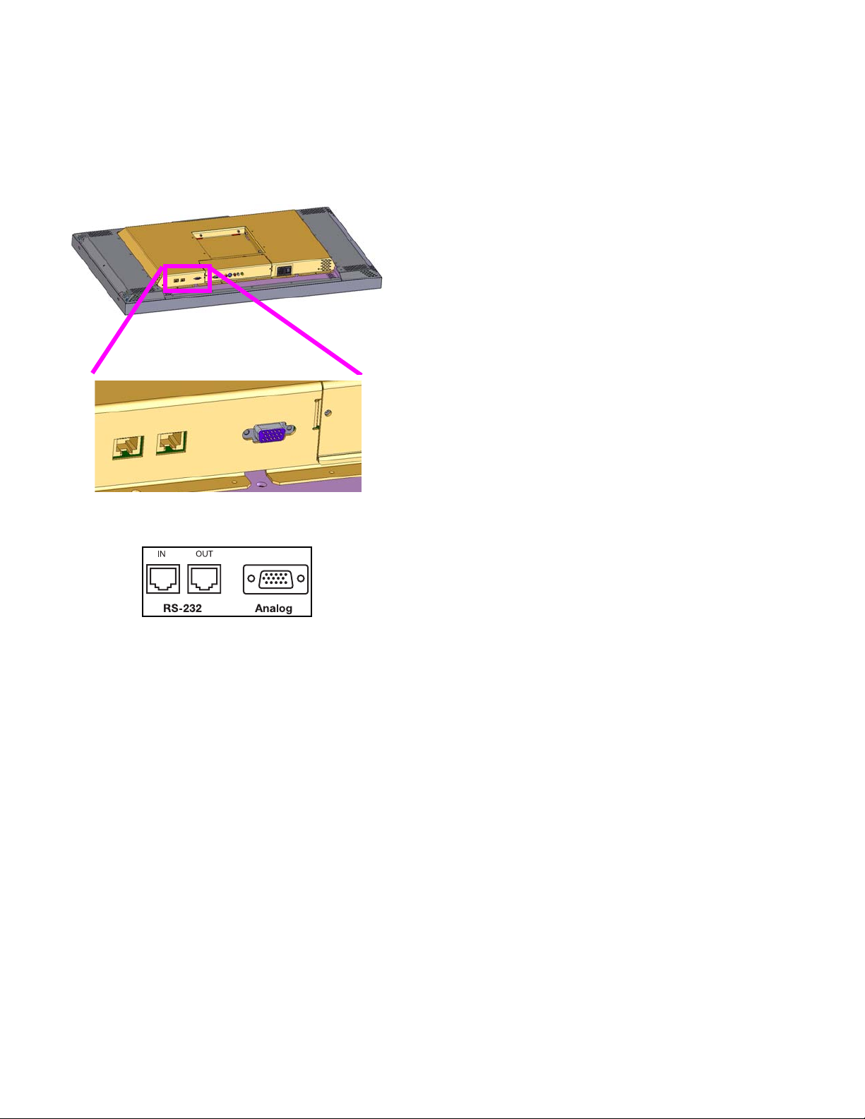
Connectors and Locations
The locations of the connectors are shown in the illustra-
tion on page 15.
✎ For exact locations and dimensions of conne ctors,
see “Connector Locations and Diagrams” on
page 114.
Computer sources
Connect analog computer sources to the analog connector., or on Video Models, connect digital computer sources
to the DVI connector.
Since computer sources are RGB, you must set the Colorspace to RGB in the Picture menu.
Video sources
Connect composite video sources to the yellow RCA
connector, S-Video sources to the S-Video connector, and
component video sources to the red, green, and blue RCA
connectors.
Component and S-Video connectors accept NTSC and
PAL video sources. The composite connector also accepts
SECAM video sources.
✎ For some customers and field upgrades, video
boards are shipped separately and must be
installed prior to use. For more information, see
“Installing the DVI Board or SDI Board” on page 6.
14
Page 21
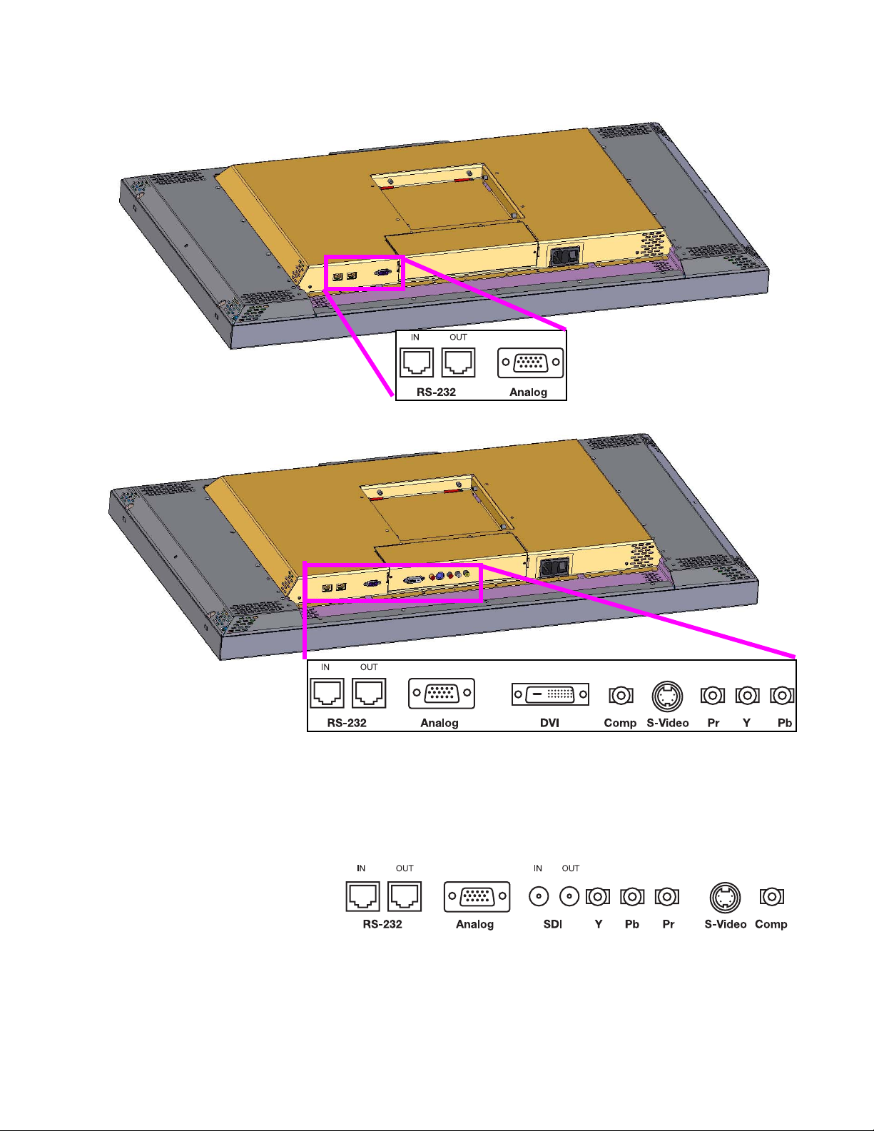
The Video Model
The Base Model (shown above) has only
an Analog VGA connector. If the Video
Model or Broadcast Model of the Bay Cat X
is shipped outside the US, video boards are
shipped separately to reduce import duties.
The Broadcast Model (not pictured) has
SDI In/Out ports in place of the Video
Model’s DVI port
15
Page 22
2.6 Connecting RS232 Communication
RS232 control is not necessary for operation, but it is a convenient way to control Bay Cat Xs from a distance.
RS232 communication allows a computer to control one or
more units using the computer’s serial port. Almost everything you can do with the remote, you can do with RS232
commands. Plus, you can send inquiries to the units and
find out the current settings and values.
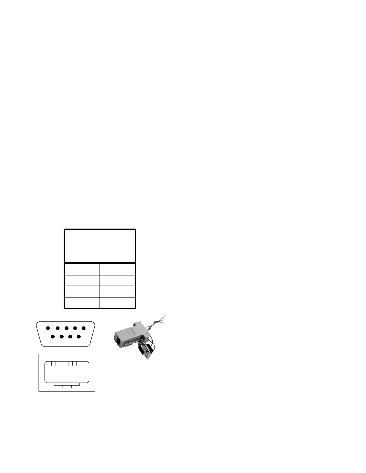
To connect a computer to the first unit, use an adapter on
the computer’s serial port connector to convert this to an
RJ45 connector.
1. Obtain an adapter that has a female 9-pin connector.
2. Wire it as shown in the illustration and table below.
Only three wires are required. Clip off the other wires,
or tuck them into the connector body.
Wiring the adapter
To go from 9-pin D-sub serial connector on the back of
the ccomputer to an RJ45 connector, use a standard
RJ45-to-9-pin adapter. Wire it internally as shown. The
wiring shown for this adapter is correct for straight-thru
cables. Straight-thru cables are wired 1-to-1, 2-to-2, etc.
Yellow wire pin 3
Black wire pin 2
Connecting for RS232 control
Use Cat-5 cable to connect from the computer (with the
adapter in place) to the first unit’s RS232 In connector.
From the first unit, connect RS232 Out to the next unit’s
RS232 In. Continue in this way until all units are in the
loop. The order of units in the loop does not matter because
each unit in the array must have a unique address.
✎ The loopthrough limit is approximately 30 un its in
typical situations. However, if the units are sp aced
far apart or the total length of the loopthrough is
very long, this limit may be reduced. You may
need multiple RS232 sources.
RS232 IDs
Each unit in the loop must have a unique RS232 ID.
Open the Serial Port Settings menu for each unit. On the
Green wire pin 5
RJ45 9-pin
63
55
32
1
23
4
5
6798
18
RJ45 looking into the socket.
female 9-pin
16
Page 23
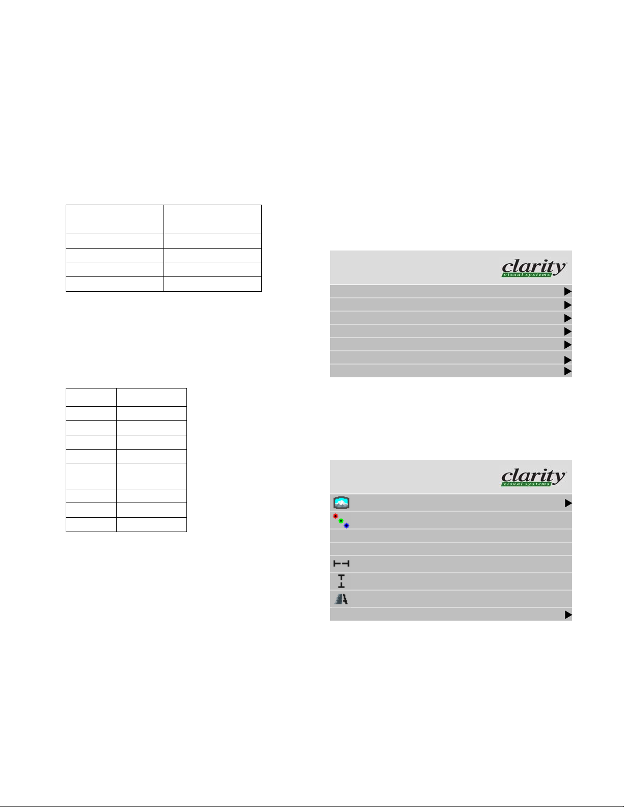
remote, press MENU. Using the up and down arrows, move
to Advanced Options and select Serial Port Settings.
w
Main Menu
have 8 units in one area divided into two groups. We might
set the ID s of the units like this:
Group ID Unit ID
11
Picture
Size & Position
Aspect Ratio & Wall
Memory
Diagnostics
Advanced Options
Program Information
Advanced Options
Color Balance
Miscellaneous Options
Backlight Settings
Serial Port Settings
Auto Setup Options
Menu Options
Message in Picture
Capture Custom Logo
Serial Port Settings
Group ID 1
Unit ID 1
ASCII Response Type Symbolic
ASCII Response Terminator CR
Baud Rate 19200
In the Serial Port Settings menu, set the Group ID and
the Unit ID so that the combined ID is unique for each
Bay Cat X in this RS232 loop.
12
13
14
21
“
22
23
24
With this scheme, we have four ways to address these
Bay Cat Xs:
Type of
Addresses
13
24
etc.
Only the specific Bay Cat X addressed will
obey the command. Also, the Bay Cat X
will respond to the host computer.
** All Bay Cat Xs in this RS232 loop will obey
the command
*4 Both the Bay Cat Xs whose IDs end in “4”
will obey this command
2* All five Bay Cat Xs in Group 2 will obey the
command
Affect on Bay Cat X
A complete list of all commands is given in “RS232
Control for Bay Cat X”, document 070-0120, available
from Clarity’s website:
Go to www.ClarityVisual.com
Click on LOGIN in upper right banner
Click on lower, blue
LOGIN NOW button
Addressing Bay Cat X
Part of the RS232 command will be an address. This
address may take several forms. For example, suppose we
17
Page 24
User name: tech
Password: help
Find Bay Cat X tech support.
Open or download “Bay Cat X RS232 Programming
Guide.”
RS232 Connector Location
For exact locations and dimensions of connectors, see
“Connector Locations and Diagrams” on page 114.
18
Page 25

3 Configuring Bay Cat X
3.1 Quick Start … 20
3.2 Setting up a Bay Cat X … 22
3.2.1 Selecting the Picture … 23
3.2.2 Adjusting Levels for Digital Computer Sources … 26
3.2.3 Adjusting Levels for Analog Computer Sources … 28
3.2.4 Adjusting Levels for Video Sources … 30
3.2.5 Aspect Ratio and Scale Mode … 32
3.2.6 Adjusting Sharpness … 35
3.2.7 Position … 36
3.3 Tiling a Display … 38
3.4 Saving Your Work & Recalling a Memory … 40
3.4.1 Memory: What Is Saved? And Where? … 42
3.4.2 Scaling and Cropping … 44
3.4.3 Adjusting Color Balance … 46
3.4.4 Zoom and Position … 49
3.4.5 Viewport Adjustment … 51
3.5 Advanced Options … 52
3.5.1 Miscellaneous Options … 56
3.5.2 Backlight Control … 58
3.5.3 Serial Port Settings … 60
3.6 Other Operations … 62
19
Page 26
3.1 Quick Start
After you select the picture source, most of the rest of setup is automatic, although you can override the automatic
settings and adjust anything manually.
Selecting the source means choosing the connector where
the picture is coming in. You’ll chose from the following
connectors, depending on the model:
Base Video Broadcast
Analog Analog Analog
DVI SDI
Composite Composite
S-Video S-Video
Component (YPbPr) Component (YPbPr)
Quick start
Connect power and turn on the power switch, which should
light. The backlight (lamp) will come on automatically. If
the power was already on, and the backlight is off, press the
remote
ON button.
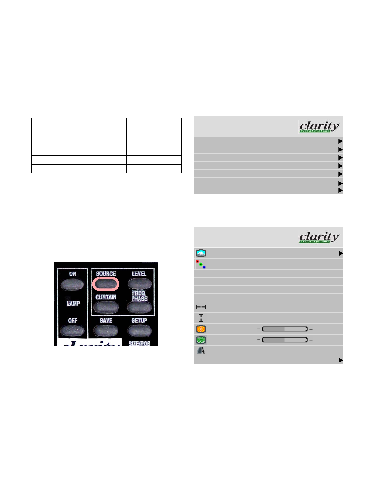
1. Aim the remote control at the lower right corner (in
landscape mode; in portrait mode, it is in the lower left
corner of the Bay Cat X) and press
SOURCE on the
remote.
2. Press
w
MENU. The Main Menu displays on the screen
Main Menu
Picture
Size & Position
Aspect Ratio & Wall
Memory
Diagnostics
Advanced Options
Program Information
3. Select Picture with the up-down arrow keys on the
remote and press
Picture
Source Analog
Colorspace RGB
Sync Type Separate H&V
Vertical Frequency (frame locked) 60Hz
Horizontal Frequency 50.00kHz
Pixel Frequency 80.10MHz
Horizontal Resolution 1366
ENTER. This opens the Picture menu.
“
The Bay Cat X looks at each of the connectors and
stops on the first one that is receiving a valid picture.
If this is successful (it may take 10 seconds) stop here.
If you have several sources connected, press
SOURCE
again to go to the next one with a picture.
If you get no picture or have other trouble, read the rest
of these steps.
✎ If you use a video source (such as from a
progressive DVD player) on the Analog or Digital
inputs, manually change the Colorsp ace to YPbPr.
Otherwise the colors will be wrong.
20
Vertical Resolution 768
Frequency
Phase
Sharpness Sharpest
Input Levels
1602
22.5°
Page 27
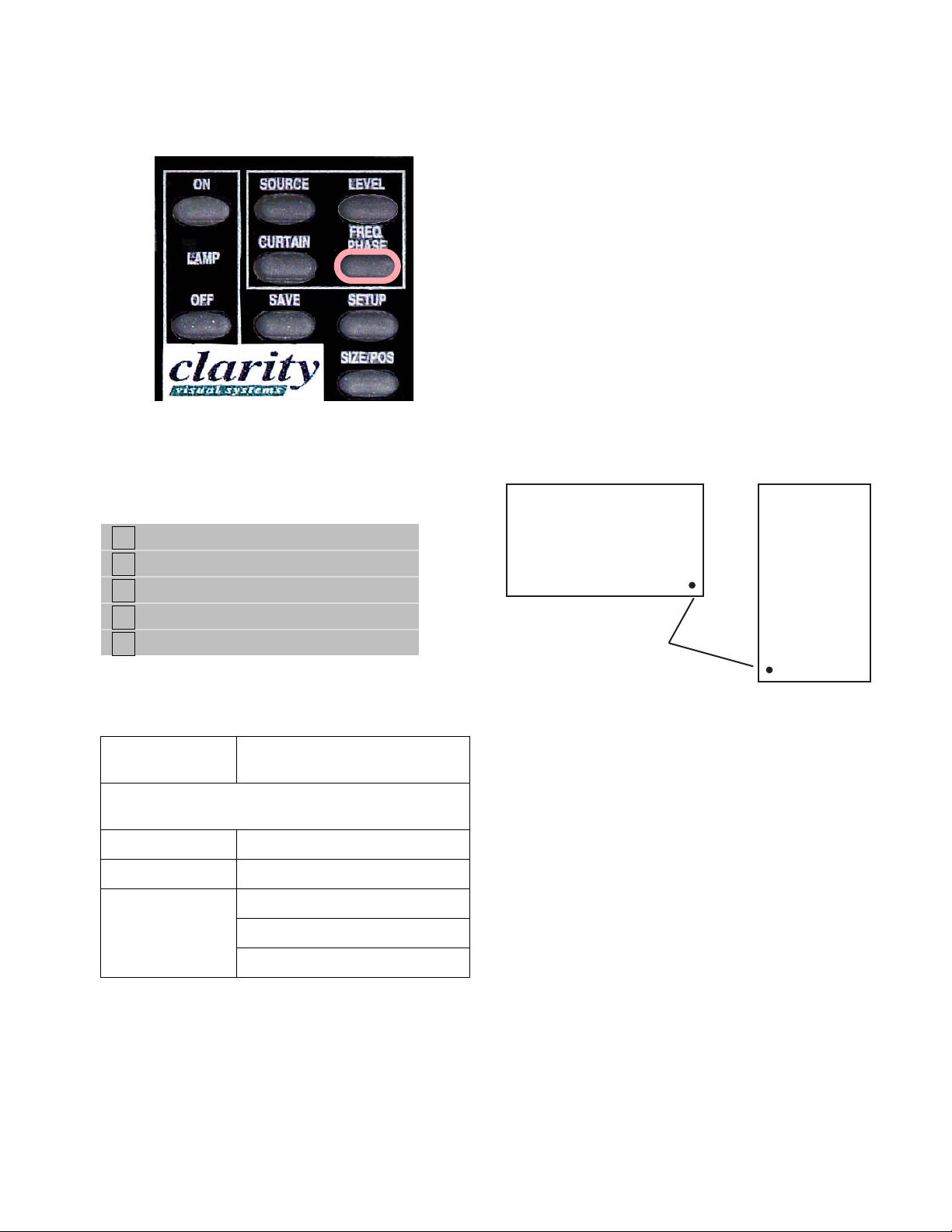
✎ TIP: The FREQ/PHASE button opens the Picture
menu directly.
4. Select Source and press E
Source menu (the menu shown below is from the
Video Model; the Broadcast Model and Base Model
have different options):
NTER. This opens the
If you see no picture …
• Check the source by connecting it to another type of
display. If the source is a laptop, maybe it has timed out
and the screen is blank. Did you enable the VGA output
on the rear of the laptop?
• Check the power switch near the AC power cord. It
should be lit.
• The IR receiver for the remote is a small hole in the
lower left corner of the display. Be sure the remote is
aimed toward it. (In Portrait orientation the IR receiver
is in the lower left corner.
About the remote
The remote control operates with IR (infra-red) signals
going to the IR receiver. The receiver is in the lower right
corner (in landscape mode; in portrait mode, it is in the
lower left corner) of the screen bezel behind a small hole.
Analog
Digital
Component (YPbPr)
S-Video
Composite
5. With the arrow keys, select the input connector you
want:
All Models Analog, usually computer sources,
VGA through UXGA
Video and Broadcast models have the following additional choices:
Video Model Digital (DVI connector)
Broadcast Model SDI (SDI In/Out ports)
Video and Broad-
cast models
6. Press
ENTER. The Bay Cat X will immediately display
Component
Composite Video
S-Video
the picture. Within a second or two the Bay Cat X will
analyze the picture and adjust to it.
Landscape
Portrait
IR Receiver
(Later, to prevent accidental adjustment of the display,
disable the remote control function using an RS232 command.)
A quick reference for all the remote buttons is found in
“Remote Control Buttons” on page 106.
If the remote doesn’t work
• The batteries in the remote are dead or installed wrong.
• The remote was not aimed at the screen.
• Something is blocking the IR receiver in the Bay Cat X.
• IR remote action was disabled by an RS232 command.
✎ The remote control has a large sprea d of its IR
radiation. It is difficult from a distance to control
only one Bay Cat X in an array. Step closer.
21
Page 28

3.2 Setting up a Bay Cat X
The source picture—from computer, video, DVD—is not always perfect in its size or resolution; it does not always
conform exactly to a standard. Bay Cat X can compensate for this.
You’ll find it easier to configure your Bay Cat Xs when you
perform the steps in the following order:
• Select the Source (Picture)
• Adjust the Input Levels
• Select the Scale Mode
• Adjust the Sharpness
• Check the Image Position
Then if you are using multiple units, whether in a banner
or an array, perform the remaining steps:
• Set up Tiling the image on multiple units
• Adjust Scaling and Cropping
• Color Balance the units
Computer sources vary quite a bit from computer to computer. They even vary between video outputs on the same
video card. Video sources vary more.
To make the Bay Cat X respond correctly to these non-
standard sources we adjust Input Levels.
• To adjust Input Levels for digital computer sources, see
page 26
• To adjust Input Levels for analog computer sources, see
page 28
• To adjust Input Levels for video sources, see page 30
How does Input Level relate to Color Balance?
To make all the displays show the same color and brightness across the whole array, you need to adjust input levels
and do color balancing.
You can do Input Levels first, or you can do Color Balance first. It doesn’t matter. But they must both be done.
What does Input Level do?
For analog computer sources adjusting to the computer’s
picture output means finding what that computer means by
black and white.
Black is supposed to be a voltage of zero coming from
the computer’s video card, but it almost never is. White is
supposed to be a voltage of 0.7 volts, but it usually isn’t
either.
The Input Level adjustment process asks you to provide
a picture from the computer that is black, then one that is
pure white. With these, you can quickly and automatically
make the display “learn” what this computer means by
black and white.
The result? Good pictures, using all the dynamic range
of color coming from the computer.
✎ For Input Levels, you must use black and white
coming from the computer you will use for the
program. Don’t make this adjustment with your
work laptop and then switch to another computer
for the display’s program of pictures.
What does Color Balance do?
Color balancing adjusts all the displays in an array so
they produce the same colors across the entire array.
Displays differ from one another because of very small
differences in the color of the light produced by the backlight and by differences in the liquid crystal panels themselves.
In color balancing you use the display’s internal test patterns of white, first, then gray. The internal pattern assures
that a pure white is used.
✎ Input Levels and Color Balan ce do not af fect each
other, but they both affect the final picture.
• To color balance the displays, see page 46
✎ If you have a stand-alone app lication, you don’t
need to do color balancing, but you can use the
Color Balancing menu to adjust the color to your
preferences. Nonetheless, you should still set
Input Levels.
22
Page 29
3.2.1 Selecting the Picture
Selecting the source (picture) manually is usually quicker than using the SETUP button.
Selecting the picture is really selecting the input connector.
If you have the Base Model, you have only one connector,
which is a HD-15 for analog computer sources. If you have
either the Video Model or the Broadcast Model, you have
the following additional connectors:
Video Model
(DVI Board)
Digital SDI
Component (YPbPr) Component (YPbPr)
Composite Composite
S-Video S-Video
Broadcast Model
(SDI Board)
Computer sources
Use the HD-15 connector for standard analog inputs, the
type we’ve used for years with computers. For digital
inputs, use the DVI connector. Either of these accepts pictures of the following common standards as well as many,
many others:
Type Resolution
VGA 640 x 480
SVGA 800 x 600
XGA 1024 x 768
SXGA 1280 x 1024
1360 x 768
1366 x 768
UXGA 1600 x 1200
HD1920 1920 x 1080
VESA 640 x 400
Component video sources
Component video sources are assumed to be YPbPr.
DVD and component video sources
DVD players have composite video and S-Video outputs, and sometimes have component video outputs from
three RCA connectors. Component video sources are
assumed to be YPbPr, so you do not need to specify the
colorspace.
Composite Video and S-Video
These two inputs accept NTSC and PAL. The Compos-
ite connector also accepts SECAM video.
To manually select the source
1. After the display is on, press
MENU on the remote.
This opens the Main Menu.
w
Main Menu
Picture
Size & Position
Aspect Ratio & Wall
Memory
Diagnostics
Advanced Options
Program Information
2. With Picture highlighted, press ENTER
This opens the Picture menu.
Picture
Source Digital
Colorspace RGB
Vertical Frequency (frame locked) 60Hz
Horizontal Frequency 50.00kHz
Horizontal Resolution 1366
Vertical Resolution 768
Sharpness Normal
Input Levels
“
✎ HDCP (High Definition Copy Protection) is not
supported.
23
Page 30
3. Select Source and press ENTER.
The Source popup menu displays to the right of the Picture menu. (For space saving reasons, only the Source
popup menu is shown below.)
Digital
Picture
Analog
Digital
Component (YPbPr)
S-Video
Composite
4. Use the up and down arrow keys on the remote to select
the type of source, and press
ENTER.
Analog
Picture
Source Analog
Colorspace RGB
Sync Type Separate H&V
Vertical Frequency (frame locked) 60Hz
Horizontal Frequency 50.00kHz
Pixel Frequency 80.10MHz
Horizontal Resolution 1366
Source Digital
Colorspace RGB
Vertical Frequency (frame locked) 60Hz
Horizontal Frequency 50.00kHz
Horizontal Resolution 1366
Vertical Resolution 768
Sharpness Normal
Input Levels
S-Video
Picture
Source S-Video
Video Standard NTSC 60 Hz/3.58 MHz
Vertical Frequency (frame locked) 60Hz
Sharpness Normal
Input Levels
Vertical Resolution 768
Frequency
Phase
Sharpness Sharpest
Input Levels
1602
22.5°
Composite
Picture
Source Composite
Video Standard NTSC 60 Hz/3.58 MHz
Vertical Frequency (frame locked) 60Hz
Sharpness Sharpest
Input Levels
24
Page 31

Component (YPbPr)
Picture
Source Component (YPbPr)
Video Standard NTSC 60 Hz/3.58 MHz
Vertical Frequency (frame locked) 60Hz
Sharpness Sharpest
Input Levels
5. Close the menu by pressing
ENTER, or let it time out.
The resolution or type of source picture currently coming in
is displayed on the line just below Source. This is grayed
out because you can’t adjust it.
25
Page 32

3.2.2 Adjusting Levels for Digital Computer Sources
Digital sources do not normally need adjustment, but the controls are there if you need them.
These controls are advanced level controls and should not
be adjusted unless you have been briefed by the factory or
are familiar with black level adjustments. They are used to
correct the digital blacks that come from video cards that
have incorrect levels.
✎ Don’t use these controls unless you have been
briefed by Clarity or you are familiar with black
level adjustments. These controls are usually not
necessary.
sw
Main Menu
Picture
Size & Position
Aspect Ratio & Wall
Memory
Diagnostics
Advanced Options
Program Information
The Input Levels menu looks different for different colorspaces. The Input Levels for Digital RGB sources is
shown below:
Input Levels
Black Level (offset)All 128
Red 128
Green 128
Blue 128
Reset Black Level to Def ault
The Input Levels menu for Digital YPbPr sources is
shown below:
“
Input Levels
Picture
Source Digital
Colorspace RGB
Vertical Frequency (frame locked) 60Hz
Horizontal Frequency 50.00kHz
Horizontal Resolution 1366
Vertical Resolution 768
Sharpness Normal
Input Levels
Black Level (offset)All 128
Red 128
Green 128
Blue 128
Hue 128
26
Page 33

27
Page 34

3.2.3 Adjusting Levels for Analog Computer Sources
This section applies to Analog RGB (computer) pictures only. The Levels are best adjusted semi-automatically.
Why adjust levels?
For analog RGB pictures the levels for black and white
vary from one computer to another, or from one video processor to another. They even vary between video outputs
from a multiple-output video card in a computer.
Your pictures will not look their best on Bay Cat X until
you adjust for these differences. This is not about adjusting
color or contrast. It’s about telling the Bay Cat X what the
computer or processor means by black and by white.
Semi-automatic adjustment
1. From the computer source, display an all-black picture.
This must come from the computer source that will be
used for the program. It does no good to use your lap-
top for this adjustment, then connect to a different computer for the program. Nor can you use the Bay Cat X’s
black test pattern. (Hint: Display a black screen using
Windows Paint program.)
✎ To adjust levels for UXGA sources that will be
displayed in One to One scale mode, perform your
adjustments using Fill All scale mode and then
switch back to One to One.
3. Select Picture, and press ENTER.
Picture
Source Analog
Colorspace RGB
Sync Type Separate H&V
Vertical Frequency (frame locked) 60Hz
Horizontal Frequency 50.00kHz
Pixel Frequency 80.10MHz
Horizontal Resolution 1366
Vertical Resolution 768
Frequency
Phase
Sharpness Sharpest
Input Levels
4. Select Input Levels and press
ENTER.
1602
22.5°
2. Press
w
28
MENU.
Main Menu
Picture
Size & Position
Aspect Ratio & Wall
Memory
Diagnostics
Advanced Options
Program Information
Input Levels
Auto Black Level (offset )
Auto White Level (gain)
Center Point 64 124 99
Black Level (offset)-All 79
Red 89
“
Green 67
Blue 83
White Level (gain) -All 99
Red 99
Green 99
Blue 99
Page 35

5. In the Input Levels menu, select Auto Black Level and
press
ENTER. This menu line says “Working…” until
the process is complete.
6. From the computer source, display an all-white picture.
7. In the Input Levels menu select Auto White Level and
press
ENTER. Wait for “Working…” to disappear.
The Bay Cat X is now adjusted to the black and white
levels of this computer using this video card. If you
change computers or video output cards in the computer, you must do this again.
✎ Black Level must be done before White Level. The
black and white pictures must come from the real
source. It doesn’t help to do this with a laptop,
then plug in the “real” computer for the program.
Full automatic adjustment of levels
Automatic adjustment of black and white levels does not
do as good a job as manual adjustment of levels. By select-
ing Do Black/White Levels box is in the Auto Setup
Options menu (Main Menu > Advanced Options > Auto
Setup Options), the Bay Cat X adjusts White levels and
Black levels to the brightest and darkest pixel, respectively,
in the picture. This does not work well because:
• some pictures do not contain a pure white pixel;
• some white pixels contain “spikes,” which makes them
seem brighter than they really are, resulting in incorrect
settings.
IF
Advanced Options
That completes the levels adjustments. If you have more
than one computer or other analog RGB source, as might
come from a switcher, you should do this for each source
and save the configuration to a memory slot.
Adjusting levels for computer sources manually
1. Display an all-black picture from the source computer.
✎ You cannot make these adjustments using the
internal Test Patterns. The black/white picture
must come from the computer that will be used for
the program material. Adjusting levels with your
laptop, then connecting to the “real” computer will
not do a proper job.
2. On the remote press L
3. In the Advanced Levels menu, select M
L
EVEL and adjust it up and down with the + \ – keys to
make the three C
EVEL.
ANUAL BLACK
ENTER POINT values go to zero. If
they do not all touch zero at the same time, use the indi-
vidual colors under M
ANUAL BLACK LEVEL to adjust
them.
✎ Do not go beyond the point where the Minimum
just goes to zero. The idea is to just touch the zero
level.
Color Balance
Miscellaneous Options
Backlight Settings
Serial Port Settings
Auto Setup Options
Menu Options
Message in Picture
Capture Custom Logo
Auto Setup Options
Retry on lost signals
Do Black/White Levels
Do Frequency
Do Phase
Do Position
Next, adjust Contrast (gain) until the Image Maximums just go to 255. Again, do not push it up after the
maximum is 255. Just touch the 255 point. You must adjust
Brightness first, Contrast second.
If the three colors are not all at 255 (or 254), adjust them
separately.
29
Page 36

3.2.4 Adjusting Levels for Video Sources
Video sources are adjusted best if a color bar test pattern is available from the video source: the DVD or VCR
player. If not, you will have to adjust by eye and the “feel” of the picture.
Adjusting the picture
1. Select a video source in the Picture menu.
2. Press
LEVEL on the remote.
✎ These controls are also used for analog sources
when you chose YPbPr Colorspace.
Now you have two choices.
• Adjust using any picture from the video source.
• Adjust using a standard color bar pattern from the
source.
Adjusting with color bars
1. If possible, use a color bar pattern from the video
source you will use for the program material. You cannot use the color bar from the Test Patterns menu.
2. In the Main Menu > Picture > Input Levels menu,
check Blue Only. You should see only the alternate
color bars, all of them blue.
3. Adjust Saturation to make the outer two color bars
match. Match them in brightness; they will already
match in color.
4. Adjust Hue to make the inner two color bars match.
5. Uncheck Blue Only
6. If the color bar pattern has a pluge, you can use it to
adjust Brightness.
Pluge
Adjust Brightness so you cannot see
the different between these two
marks,
but you can see the difference
between these two marks.
✎ When a video source is selected, Auto Setup
Options is not available. Adjustments must be
made manually.
30
Adjusting with any picture
This procedure must be done after you adjust color bal-
ance (page 46).
1. Choose pictures that have blacks and whites represented as well as a variety of colors.
2. Adjust Contrast, Brightness, Saturation and Hue on one
Bay Cat X until it looks satisfactory.
Page 37

3. Adjust all the other Bay Cat Xs in the array so they
have the same values for Contrast, Brightness, Saturation and Hue as the first Bay Cat X.
w
Main Menu
Picture
Size & Position
Aspect Ratio & Wall
Memory
Diagnostics
Advanced Options
Program Information
Saturation
Match
“
Match
Adjust Saturation so the outside bars match
when Blue Only is checked.
Picture
Source Composite
Video Standard NTSC 60 Hz/3.58 MHz
Vertical Frequency (frame locked) 60Hz
Sharpness Sharpest
Input Levels
Input Levels
Brightness 140
Contrast 165
Saturation 150
Hue 128
Blue Only
Hue
Match
Adjust Hue so inside bars match when
Blue Only is checked.
Match
31
Page 38

3.2.5 Aspect Ratio and Scale Mode
The aspect ratio of any picture is its height divided by its width. H / W = Aspect Ratio
The native aspect ratio of the Bay Cat X screen is 1.77,
which is sometimes referred to as 16:9. This is the WXGA
and HDTV picture format.
1366 horizontal pixels, 768 vertical pixels
1366 / 768 = 1.77
Many pictures do not have this aspect ratio. Standard
television, VGA, SVGA, and XGA signals are 1.33. Movies from DVDs vary depending on the original film format,
often 1.85. The larger the number, the “wider” the picture
seems.
When the incoming picture is a different aspect ratio
from the screen, Bay Cat X gives you six choices to make it
fit. To select the scaling mode, go to Main Menu > Aspect
Ratio & Wall > Scale Mode.
w
Main Menu
Picture
Size & Position
Aspect Ratio & Wall
Memory
Diagnostics
Advanced Options
Program Information
Aspect Ratio & Wall
Scale Mode Fill All
Justify Center
Overscan 0%
Border Color Black
Wall Width 1
Wall Height 1
Unit Column 1
Unit Row 1
Wall Mode
Frame Compensation
Frame Height 97 pixels
Frame Width 157 pixels
The six Scale Modes are “radio” buttons; you can only
choose one.)
Fill All
Crop
Letterbox/Pillarbox
Widescreen (16x9)
Normal Video (4x3)
One to One
✎ The Scale Mode menu icons change to indicate
the effect each mode will have on the picture
based on the Justify and Scale Mode settings, and
the source resolution.
Fill All makes the picture fit top-to-bottom and left-to-right
regardless of how this stretches or compresses the picture.
Fill All distorts the picture, when the aspect ratio of the
incoming picture is not the same as the Bay Cat X screen.
Letterbox/Pillarbox expands the picture until the first
“
edges (top-bottom or left-right) touch the border of the display, and then fills in the other sides with a solid color.
Crop expands the picture until the second edges touch the
border and let the other edges of the picture fall outside the
display and get cropped.
Widescreen (16x9) forces the aspect ratio to 16 x 9 (1.77),
the standard for many DVD movies. This will distort any
picture other than 16X9 aspect ratio pictures. Widescreen
can be used to display anamorphic DVDs on an array.
Normal Video (4x3) forces a 4 x 3 (1.33) aspect ratio, the
ratio of standard television. Normal Video is used to display YPbPr video on the analog input port. Its resolution is
720x640 which is not 4x3 but it should be displayed as 4x3
(the pixels aren't square).
One to One maintains the original size and aspect ratio of
the picture. This may leave blank areas on all four sides.
For instance, a VGA picture (640 × 480) will occupy only a
small area in the center of the screen. For UXGA sources,
this will crop the picture top and bottom.
32
Page 39

Affect on Input Type
Scale Mode
Standard Video or VGA/SVGA/XGA Source 1080i Computer Source
Fill All Distorts (expands) width of image Displays at native resolution without distortion
Crop Crops top and bottom of image; fits width of image
Displays at native resolution without distortion
without distortion
Letterbox/
Pillarbox
Fits height of image without distortion; fills width with
border
Displays at native resolution without distortion
Widescreen Stretches image to fill width without affecting height Displays at native resolution without distortion
Normal
Video
Fits height and width of image without distortion; fills
width with border
Fits height of image, compresses width and fills with
border
.
33
Page 40

Affect on Input Type
Scale Mode
One to One Displays image without distortion at actual size with
Standard Video or VGA/SVGA/XGA Source 1080i Computer Source
border on all sides
Displays at native resolution without distortion
34
Page 41

3.2.6 Adjusting Sharpness
After you set the Scale Mode to the one you will use for the program, select the Sharpness level in the Picture
menu to reduce scaling artifacts. If you are not scaling your image, you may skip this section.
Sharpness Settings
The Sharpness setting is in the Picture menu.
Picture
Source Analog
Colorspace RGB
Sync Type Separate H&V
Vertical Frequency (frame locked) 60Hz
Horizontal Frequency 50.00kHz
Pixel Frequency 80.10MHz
Horizontal Resolution 1366
Vertical Resolution 76 8
Frequency
Phase
Sharpness Sharpest
Input Levels
1602
22.5°
There are five levels of sharpness:
•Sharpest
•Sharp
• Normal
•Soft
•Softest
Normal is the default. It is essentially a “pass through”
with no effect on the picture. Make any adjustments to
sharpness with the picture scaled, that is, with the Scale
Mode set the way you will use it. Use Sharpness to reduce
artifacts of scaling.
✎ The Sharpness adjustments are in effect only
when the image is scaled.
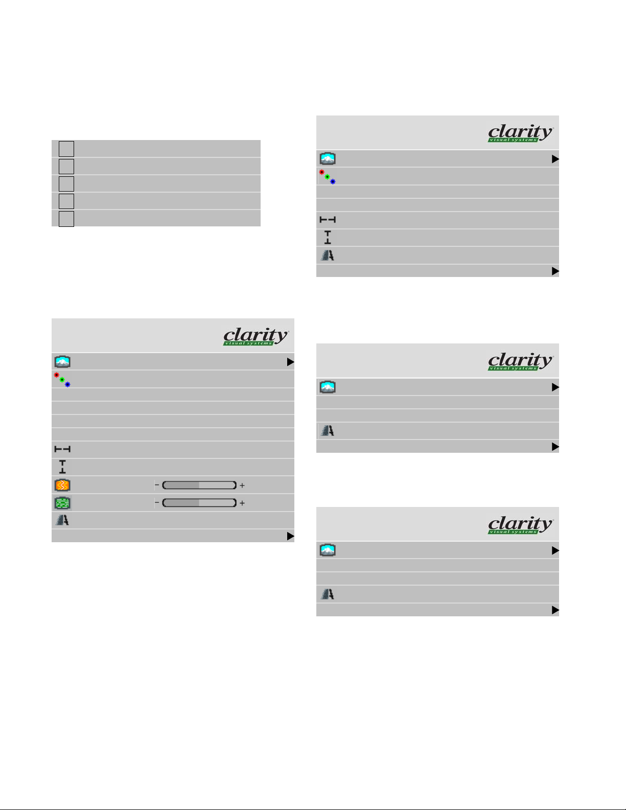
From the Aspect Ratio menu (Main > Aspect Ratio &
Wall), select Scale Mode.
Aspect Ratio & Wall
Scale Mode Fill All
Justify Center
Overscan 0%
Border Color Black
Wall Wi dth 1
Wall Height 1
Unit Column 1
Unit Row 1
Wall Mo de
Frame Compensation
Frame Height 97 pixel s
Frame Width 157 pixels
Press E
NTER to move to the Scale Mode sub-menu. Use
the up and down arrow keys to highlight the mode you
need. Press E
NTER to select the mode...
Fill All
Crop
Letterbox/Pillarbox
Widescreen (16x9)
Normal Video (4x3)
One to One
✎ The Scale Mode menu icons ch ange to indicate
the effect each mode will have on the picture
based on the Justify and Scale Mode settings, and
the source resolution.
35
Page 42

3.2.7 Position
This moves the picture image on the screen, but does not move the menus.
Image Position
In the Picture Position menu, the four arrow keys move
the picture.
w
Main Menu
Picture
Size & Position
Aspect Ratio & Wall
Memory
Diagnostics
Advanced Options
Program Information
Size & Position
“
Picture Position
Zoom Window Top & Left
Zoom Window Bottom & Right
Viewport Window Top & Left
Viewport Window Bottom & Right
Reset All Windows to Default
Picture Position
Use arrow keys to move image
Horizontal Position 168
Vertical Position 19
The Horizontal Position number shows the number of
pixels from the beginning of H sync to the first active pixel.
Because there are many black pixels after H sync, this number will not be zero when the picture is at the left border of
the screen.
The Vertical Position number is the number of lines
from V sync to the first active line, so it will not be zero
when the picture is at the top of the screen.
36
Page 43

37
Page 44

3.3 Tiling a Display
Whether you use Clarity’s Big Picture™ or an external video processor, your goal is to make the picture fit
together properly at the edges.
Using an external processor
The processor divides a single picture into several sections and sends each part on a separate cable. Connect these
cables to the proper Bay Cat X.
You can still position the picture with the Bay Cat X
controls, or, with most processors, position and zoom the
picture with the processor controls.
Using Clarity’s Big Picture™
To show the same source on all the Bay Cat Xs in an
array you’ll need to use an external distribution amplifier.
For each unit, set the Aspect Ratio & Wall menu for the
same array size.
w
Main Menu
Picture
Size & Position
Aspect Ratio & Wall
Memory
Diagnostics
Advanced Options
Program Information
Wall Width and Wall Height are the number of units
wide and high for the picture. This may be different from
the physical array size. You could build a 4x4 array of
Bay Cat Xs and use Wall Mode to put a single picture on
the four cubes in the upper left corner, for instance.
• Unit Column and Unit Row represent the position of
the Bay Cat X in this “array.” For example, in a 2 x 3
array of Bay Cat Xs, the unit at the top left corner of the
array would have a Unit Column value of 1 and a Unit
Row value of 3
• Wall Mode, when checked, turns on the Clarity Big
Picture™ feature. When not checked, the unit shows
the whole picture.
✎ Each unit in a “array” gets the whole picture by
feeding them all with a distribution amplifier. The
Aspect Ratio & Wall menu tells the unit what
portion of the entire picture to display.
Frame Compensation
When video units are used in an array, the intent is to
display a large version of an image. However, even the thin-
“
nest of mullions break up the image oddly.
38
Aspect Ratio & Wall
Scale Mode Fill All
Justify Center
Overscan 0%
Border Color Black
Wall Width 1
Wall Height 1
Unit Column 1
Unit Row 1
Wall Mode
Frame Compensation
Frame Height 97 pixels
Frame Width 157 pixels
Page 45

One way around this is to adjust the image. Imagine
looking out a window made up of many panes of glass. The
image you see is partially obscured by the frames, but your
mind assembles the image and ignores the frames.
Frame compensation allows you to mimic the mind’s
function by “hiding” portions of the picture (as if the mullions were actually hiding the image) and allow the distributed image to appear as one very large image.
To hide pixels to the left and right of images, set Frame
Width.
To ensure that images containing diagonal lines remain
correctly diagonal, turn on Frame Compensation.
Depending on how closely you space the units, you must
determine how much of the picture to “hide” behind
Bay Cat X’s mullions and the space between units.
WARNING
The Bay Cat X generates heat. Plan your
array installation to provide adequate ventilation or cooling to ensure that your Bay Cat Xs
operate within normal usage guidelines. For
more information, see “Optimizing Your Clarity
Display” on page 116.
If you have any questions about your installation, consult Clarity Visual Systems for proper Bay Cat X array
configuration guidelines.
To hide pixels at the top and bottom of images, set
Frame Height.
39
Page 46

3.4 Saving Your Work & Recalling a Memory
Some saving is done automatically, but there are big advantages to saving your work manually.
How automatic save works
Whatever changes you make with the remote control or
RS232 commands, these changes are saved automatically.
If you change sources (switch to another input connector)
and come back to this source, everything you did before
will be “recalled.” Things will look like they did before.
Suppose you make adjustments to an SVGA source on
Analog 1, then you feed a UXGA source to Analog 1 and
make new adjustments. Then you switch to the S-Video 1
connector and do some more setup for it.
Later you switch to the Analog 1 input again, and this
time it has the SVGA source from before. The Bay Cat X
will recognize that it has seen this source before, or at least
a source with these characteristics, and will recall the
SVGA settings you established before.
This kind of recall includes Input Levels, Position, and
Frequency, but it does not include Wall Mode and any Big
Picture adjustments you made. Those need to be recalled
from memory slots.
Manually saving to memory slots
Bay Cat X has 40 numbered memory slots, and this is
the best way to save. Recall is fastest from memory slots.
First, set up the Bay Cat X the way you want it, including all the adjustments listed in this section. Then press the
SAVE button twice. This opens the Save grid.
Navigate to an unchecked slot number, or to a checked
slot if you want to overwrite what’s already saved. Press
ENTER.
This menu shows all the data that will be saved. You
can’t change anything but the name in this menu. To save
immediately, press
ENTER. The appearance of this menu is
somewhat different for digital and video sources, reflecting
what is saved for them.
Use the left-right arrow keys to navigate along the line.
Use the up-down keys to change the character at that point.
Press
PREV when finished. Then select Save Now and press
ENTER again.
If you have RS232 control, there are commands to send
a string name to a memory slot, saving time.
How to recall a memory slot
1. Press
SAVE once to open the Recall grid.
2. Navigate to the slot you want to recall. You can only
land on slot numbers that are not empty (have checks).
Press
ENTER to open the Recall detail menu. If this slot
number has exactly the same settings are currently
being used, a (Current) message appears on the top line.
3. The only line you can select is Recall Now. Press
ENTER.
Advantages of saving configurations to memory slots
• You can compare multiple settings quickly
• You don’t have to repeat settings when comparing
entire configurations
• You can revert to a known good setting when testing
new configurations
To change the name of the memory slot
The default name is an abbreviated description of the
contents. In this case, the name tells you that the source is
connected to Analog 1, which is an XGA picture. This unit
is part of a 2x2 array, and it’s the unit lower left corner (column 1, row 2).
If your customer wants or needs a more descriptive
name, select the Name line and press
40
ENTER.
Page 47

ENTER
ENTER
41
Page 48

3.4.1 Memory: What Is Saved? And Where?
Bay Cat X’s automatic memories work well, but the best way to save and recall is with the numbered memory
slots, because they recall everything.
In the Bay Cat X some parameters (values) are associated
with the mode. The mode is primarily the horizontal and
vertical resolution and the vertical frequency of the incoming source picture. It is more than this, but if you think of it
this way, you will be close enough.
Some parameters are associated with the input. The
input in this instance means the input connector: Analog 1,
Digital, Composite Video, etc.
✎ The parameters specific to Mode and Input are
saved in memory slots.
Some parameters are global, that is, they are not associated with either the mode or the input connector, and are
not saved to memory slots. They are universal.
Specific to the
Parameter
Mode Input
ASCII Response Term. x
ASCII Response Type x
Auto Codes x
Global
Specific to the
Parameter
Mode Input
Hue x
Justify x
Menu H Position x
Menu Timeout x
Menu V Position x
Phase x
Plug and Play (EDID) x
Position, Horizontal x
Position, Vertical x
Resolution, Horizontal x
Resolution, Vertical x
Retry On Lost Signal x
Saturation x
Global
Auto Backlight On x
Baud Rate x
Black Level: R, G, & B x
Brightness (video) x
Color Balance (all values) x
Colorspace x
Contrast (video) x
Curtain Pattern x
Do Black/White Levels x
Do Frequency x
Do Phase x
Do Position x
Frequency x
Group ID x
Sharpness x
Unit ID x
White Level: R, G, & B x
Memory
The Bay Cat X remembers the last 10 modes it received
and all the mode parameters associated with them.
Switching modes
For instance, suppose you set up the Black and White
Levels for a 1024x768 @ 65Hz vertical from a computer
connected to Analog. Then later, using the same input connector but a different computer you set up the Bay Cat X
for a 1600x1200 @ 60Hz. You re-adjust the Black and
White Levels, because they are different.
Still later you plug in the first computer with its
1024x768 @ 65Hz picture. Immediately, the Bay Cat X
recognizes that it has seen this signal type before, and it
recalls the Black and White Levels from its internal memory.
42
Page 49

It does not Do Frequency or Phase or anything else,
because it recognizes that this input was used before, and
the previous settings are probably correct.
Possible issue with Mode specific memory
Suppose that after setting up the 1024x768 and
1600x1200 pictures, you connect a third computer that is
1024x768, but it has a different requirement for Black and
White Level. In this case, the Bay Cat X would use the
default values for these levels.
To prevent this from happening, use the memory slots as
described in “Saving Your Work & Recalling a Memory”
on page 40.
Switching input connectors
Now suppose you use Digital to bring in a picture that
uses the component YPbPr video. You change the Colorspace setting to YPbPr. If you switch back to Analog in the
Picture menu, the Bay Cat X switches back to the RGB
Colorspace, because Colorspace is specific to the input
connector.
Possible issue with Input specific memory
What happens if you switch back to Analog and the picture there is YPbPr? The Bay Cat X has no way to know
this, no way to detect the difference between RGB and
YPbPr, so it will use the wrong Colorspace.
To prevent this from happening, use the memory slots as
described in “Saving Your Work & Recalling a Memory”
on page 40.
Global parameters
In none of the examples above does the Bay Cat X try to
change the Baud Rate or the Color Balance values, because
these items are saved globally.
43
Page 50

3.4.2 Scaling and Cropping
Sometimes the picture does not fit the array. If the source picture is video from a DVD, the aspect ratio is probably
1.77 (16x9), the same as HDTV.
✎
The aspect ratio of a picture is its width divided by
its height. 1024 ÷ 768 = 1.33
The aspect ratio of a Bay Cat X is 1.77 (16x9), the same as
HDTV. When the source picture’s aspect ratio is not the
same as the Bay Cat X array, you have to do something to
make the picture fit. You have some basic choices:
• Fill the area both ways. This will produce some distortion in the picture. Circles will not be round.
• Put the picture in without distortion and crop off the
sides (or top and bottom).
• Put the picture in without distortion and fill the extra
space with black or some other solid color.
• Force an aspect ratio, such as 16 x 9 or 4 x 3.
Below is a 1.77 picture shown on a 3x3 array of
Bay Cat Xs. The picture fills the array nicely, and there is
no distortion or cropping.
Scale Mode determines how the picture will be made to fit
the array.
• Fill All means that the picture will touch the borders of
the array all around, even if this means stretching (and
distorting) the picture in one direction. The picture had
to be stretched sideways to fill the screens.
• Letterbox means expand the picture until the first
edges (top-bottom or left-right) touch the border of the
array, then fill in the other sides with a solid color.
• Crop means expand the picture until the second edges
touch the border and let the other edges of the picture
fall outside the array and get cropped. Here the width is
filled, there is no distortion, but the top is cropped off.
This would happen when the Justify is B
OTTOM.
Let’s start with a 1.33 (4x3) picture, the aspect ratio of normal TV, and put it on this same array of Bay Cat Xs. Here
is the original picture.
44
• Widescreen means force the aspect ratio to 16 x 9
(1.77), the standard for many DVD movies.
• Normal forces a 4 x 3 (1.33) aspect ratio, the ratio of
standard television.
Justify determines how the picture will be placed in the
array.
• If the picture is too wide for the array and is cropped on
the sides, you can choose Left, Center, or Right.
Page 51

• If the picture is too tall for the array and is cropped top
and bottom, you can choose To p, Middle, or Bottom.
• Similar choices are made if the picture is letterboxed.
Border Color determines the color of the “extra” space
around the picture if it doesn’t fill the screen. The choices
are:
• Black
•White
•Red
•Green
•Blue
• Dark Red
• Dark Green
• Dark Blue
When the Scale Mode is Fill All, the Border Color line will
be grayed out, because there will be no border.
45
Page 52

3.4.3 Adjusting Color Balance
Color Balance is used to match the colors of adjacent displays when several Bay Cat Xs are arranged in an
array. You may also use it to adjust the color of a single display.
For one Bay Cat X only
If you have only one display, the Color Balance controls
can be used to set the color temperature of the single display.
w
Main Menu
Color Balance
Color Temperature 8500K (Cool)
White Balance - All (Clipboard)
Red 100 (100)
Picture
Size & Position
Aspect Ratio & Wall
Memory
Diagnostics
Advanced Options
Program Information
Advanced Options
Color Balance
Miscellaneous Options
Backlight Settings
Serial Port Settings
Auto Setup Options
Menu Options
Message in Picture
Capture Custom Logo
Green 100 (100)
Blue 100 (100)
Gray Balance - All
“
Red 7 (7)
Green 7 (7)
Blue 7 (7)
Test Pattern Off
Hide Menu
Copy to Clipboard
Recall From Clipboard
Reset to Defaults
Understanding Color Temperature
Different "Pure white" light sources do not always have
the same color. For instance, light from an incandescent
bulb is much more yellowish than light from direct sunlight. "Color Temperature" is a way of measuring these
color differences. In general higher color temperature numbers are more bluish or "cooler". You may have a reason for
wanting your unit to be a specific color temperature. For
instance, if you are using your Bobcat X in a television studio where you will be videotaping the content, you will
want a low color temperature. The default color temperature for the Bobcat X is 8500k. This is the native color temperature of the LCD panel. You may choose a different
color temperature by setting it in the Color Balance menu.
46
Page 53

Adjusting Color Temperature
Select Color Temperature in the Color Balance menu
and select from 3200°K (Warm), 5500°K, 6500ºK, and
8500°K (Cool).
Each of these selects a set of White Balance values to
give the picture a warm (3200K) to cool (9500K) appearance.
To adjust an array of Bay Cat Xs for Color Balance
The object of color balancing is to make the individual
units in an array show the same colors. When we see a yellow car move across a video array from one display to
another, we want it to have the same color for the whole
trip, not change from yellow to maroon to orange.
The displays naturally have slightly different colors
from one display to the next, because of slight variations in
the backlights and LCDs. This cannot be avoided, but we
can compensate for it with color balancing.
Color balancing is subjective. It may seem strange at
first, but it gets easier with practice. Fortunately, you don't
have to match all the colors; you only have to match whites
and grays.
When you make all the displays look the same with
White and Gray, all the other colors will look the same. It is
not necessary to achieve a perfect white or a perfectly colorless gray. It is only necessary that all the displays look
alike when they display white and gray.
CAUTION
Never try to match the colors of the display
units with the Black and White Level controls
or with the Video Controls. You will not like the
results if you do.
Color Balancing
1. Turn on all the units in the array and let them warm up
for at least five minutes. The lamps must be thoroughly
warm before you color balance.
2. Open the Backlight Control and Status menu (
> A
DVANCED OPTIONS > BACKLIGHT CONTROL).
Backlight Control
Auto Backlight on
Turn Backlight off with no Source (DPMS)
DPMS Delay 1 hr
Backlight Control Mode Manual
Backlight Intensity 100
MENU
a) Set Backlight Mode Control to Manual.
b) Set (or confirm) Backlight Intensity to 100%.
3. For each Bay Cat X in the array, do the following:
a) Open the Color Balance menu on all displays in the
array. (
MENU > ADVANCED OPTIONS > COLOR BAL-
ANCE).
✎ If the array has never been color balanced, make
sure you start with the same color temperature
setting on each unit. If you are not interested in
achieving a specific color temperature, use the
default of 8500K, which is the brightest. If the unit
has been color balanced before, it will display
C
USTOM in its color temperature setting, because
the balance values don’t match any of the pre- se t
color temperatures.
b) Highlight Test Pattern and use the left-right arrow
keys until it says White.
✎ Always use the internal Test Patterns for color
balancing, not an external pattern.
4. When all displays are white, find the least bright display in the array. This will be the “baseline” display,
and you will not adjust it. All other displays will be
adjusted to this baseline display.
✎ Why pick the “least bright” display? Why not pick
the brightest and adjust to it? When the White
value is 100, the display is a bright as it can get.
You are adjusting for slight variations in backlight
brightness.
5. Choose a display next to the baseline display and adjust
its White values (red, green, and blue) to make it match
the baseline display. Concentrate on the center of the
47
Page 54

displays, not the adjacent edges. (If you can’t bring theses settings down to match the baseline, maybe you
didn’t choose the darkest display.) Do not adjust the
Gray values at this time.
6. Continue with other adjacent displays until all the displays have the same appearance when white. Be careful
not to change the values of displays once you are satisfied with them. Use Hide Menu to keep from setting
other displays and allow you to see more of the white
field. To unhide the menu, press E
NTER
✎ The menus will automatically turn off after a time
determined in Menu Options (
Options > Menu Options > Menu Timeout). If
Menu Timeout is 0 (zero), the menus stay up
indefinitely.
MENU > Advanced
Color Balance values are saved for all input sources in
the same memory location. Color Balance is the same for
all sources.
100
Bright
Dark
Changes in the
White value moves
this end point.
Changes in the White values
affect the Gray values.
Output brightness
Black
Input Signal
31
0
White
7. When all displays look the same for White, choose the
Gray test pattern in all displays.
8. Choose any display as the new baseline display. It does
not need to be the baseline display you used for White.
9. Adjust all the displays in the Gray part of the Test Patterns menu until they match the baseline display. Do
one display at a time. Again, match the center part of
the picture, not the edges.
10. When all displays match in Gray, close all the menus.
The test pattern automatically turns off.
Tips for color balancing
• Copy to Clipboard will save all the current settings to a
temporary memory. You can then make more adjustments to see if it gets better or worse. Recall from Clipboard will restore these saved settings. The clipboard is
only for testing. These values are not saved when AC
power is off.
Changes in the Gray values do
not affect the White values.
Changes in the
Gray value move
Output brightness
this mid point.
15
0
Input Signal
• Removing red has the same effect on hue as increasing
blue and green together. The Color Balance menu slider
bars have colored bulbs at each end to tell you what the
effect will be of moving a color toward that end.
• Stand back from the display array and directly in front
of it to get the overall view.
• Small changes are difficult to see at first, particularly
with White. Change the value by 4 or 5 steps to see the
difference. If you are going the wrong way, go back and
move it 4 or 5 steps in the other direction. If neither of
these bring you closer to a match, try another color.
• When you don’t know which color to change, pick one
at random and change it 3 or 4 steps. The result will be
either better or worse. If worse, go the other way with
that color. If that is also worse, put this color back
where you started and to the same with another color. If
everything you do makes the match worse, you must be
close to the ideal point.
48
Page 55

3.4.4 Zoom and Position
Position moves the picture on the screen. Zoom adjusts the edges of the picture to make it fit with the other pictures in an array.
Position
Press the
MISC button once to open the Picture Position
menu. The four arrow keys move the picture on the screen.
Picture Position
Use arrow keys to move image
Zoom menu entries
• Image Resolution is the resolution of the source pic-
ture.
• This Unit is the number of pixels this unit is using of
all the incoming pixels, followed by the size of the
array (from the Wall & Aspect Ratio menu) and the
Column and Row of this unit.
Using Zoom and Position
Picture Position is usually used to center the picture on
the screen.
Zoom is primarily used to adjust the edges of the picture
when one picture is spread over several units. Whether you
use Clarity’s Big Picture™ or an external video processor
to make one picture cover several units, the Zoom controls
can make the edges fit together.
w
Main Menu
Picture
Size & Position
Aspect Ratio & Wall
Memory
Diagnostics
Advanced Options
Program Information
“
Horizontal Position 168
Vertical Position 19
The numbers for Horizontal and Vertical Position refer
to the number of pixels from sync to the first displayed
pixel. These numbers get smaller as the picture moves up
and to the left.
Zoom
Zooming (Main > Size & Position > Zoom Window)
is used mainly to make the edges of a large picture—one
that covers many Bay Cat X screens—fit each other sideto-side and top to bottom.
(
Size & Position
Picture Position
Zoom Window Top & Left
Zoom Window Bottom & Right
Viewport Window Top & Left
Viewport Window Bottom & Right
Reset All Windows to Default
49
Page 56

Zoom Top & Left
Arrows move top and left
0
0 0
0
Image Resolution 1920 x 1080
This unit 1920 x 1080
Zoom Bottom & Right
Arrows move bottom and right
0
0 0
0
Image Resolution 1920 x 1080
This unit 1920 x 1080
50
Page 57

3.4.5 Viewport Adjustment
The Viewport menus adjust the image on the LCD.
What is Viewport?
The Viewport menu (Main > Size & Position > Viewport) adjust the number of pixels actually used on the LCD.
You can’t increase this number, naturally, but you can
reduce it.
• Image Resolution shows the resolution of the image.
This has nothing to do with the resolution of the source
picture.
• Viewport shows the number of LCD pixels being used.
w
Arrows move top and left
Viewport Top & Left
0
Main Menu
Picture
Size & Position
Aspect Ratio & Wall
Memory
Diagnostics
Advanced Options
Program Information
(
Size & Position
Picture Position
Zoom Window Top & Left
Zoom Window Bottom & Right
Viewport Window Top & Left
Viewport Window Bottom & Right
Reset All Windows to Default
“
0 0
0
Image Resolution 1920 x 1080
Viewport 1920 x 1080
0
Viewport Bottom & Right
Arrows move bottom and right
0
0 0
0
Image Resolution 1920 x 1080
Viewport 1920 x 1080
51
Page 58

3.5 Advanced Options
Menu Options moves the menus to other places on the screen. Auto Adjustment Options sets what will happen
automatically and what will not.
Menu Options
These controls move the menu to a different position on
the screen or rotate it for Portrait orientation. Menu Timeout is set here.
w
Main Menu
Picture
Size & Position
Aspect Ratio & Wall
Memory
Diagnostics
Advanced Options
Program Information
Advanced Options
Color Balance
Miscellaneous Options
Backlight Settings
Serial Port Settings
Auto Setup Options
Menu Options
Message in Picture
Capture Custom Logo
decrease the distance from the left side of the screen to the
left side of the menu. The number indicates the how far
across the screen, in percent, the menu starts.
V Position moves the menus up and down. Use the left
and right arrow keys (on the up-down keys) to move the
menu. The number indicates how far down the screen the
menu is in percent. It is not possible to move the menu to
the bottom of the screen.
Menu Timeout determines how many seconds the menu
will stay on the screen without any activity. Never Time-
out means the menus will not automatically disappear. The
maximum time is 60 seconds. The shortest possible time is
2 seconds. The default value, if you have never changed
“
Menu Timeout, is Never Timeout.
Rotate Menu makes the menus readable when the
Bay Cat X is arranged in portrait or landscape orientation.
✎ Rotate Menu does not rotate the picture. It only
arranges the menus so they read the same way
the picture does. To use the Bay Cat X in portrait
mode, your source image must be rotated.
Auto Adjustment Options
Each of the “switches” in Auto Options can be turned on
or off by selecting it (up-down arrows) and pressing
Auto Setup Options
ENTER.
Menu Options
H Position 100
V Position 8
Menu Timeout Never Time Out
Rotate Menu None
H Position moves the menus (all of them) left and right on
the screen. Use the left and right arrow keys to increase or
52
Retry on lost signals
Do Black/White Levels
Do Frequency
Do Phase
Do Position
When the box is checked, the action will occur under
these circumstances:
• When a new source is detected that has not been
detected before. (See ’About the input memories’ on
this page and “Input system caches” on page 63.)
Page 59

• When you press the SETUP button.
Retry on lost signal occurs only when the present signal
(picture) disappears or changes in some way. If this item is
not checked, the Bay Cat X will not try to sync to a new
signal. Keep this menu item checked.
Note that searching will not happen just because the picture goes black. Black, from video or from a computer, is a
valid picture. The signal itself (the sync pulses) must be lost
to trigger a search.
The several Do items in this menu will, if checked, happen
in these situations:
• If a new signal is acquired, either through a search to a
different connector or because source picture changed
modes, such as from WXGA to UXGA, each of the
checked items occurs in the order listed in the menu.
• When you press the
SETUP button on the remote, each
of the checked actions occurs in the order given in the
menu.
Do Quick Black/White Levels searches for the bright-
est and darkest pixels in the picture and adjusts to these.
Black and White Levels are best done semi-automatically
(see “Adjusting Levels for Analog Computer Sources” on
page 28) so leave this unchecked.
Do Frequency and Do Phase find the frequency and
phase (separately) of the computer picture and adjust to
them. This works best on a picture that has lots of sharp
changes in brightness, such as text (adjacent white and
black pixels).
Do Position centers the picture on the screen.
✎ Aspect Ratio is specific to the source, which
means it applies to all modes. It does not change
when the system recalls a memory from cache.
Setup button
The
SETUP button on the remote starts the “Do” pro-
cesses. Each Do that is checked will begin, one at a
time, until all are adjustments completed.
Logo Capture
The capture menu is used to create a custom splash
screen that appears when the unit is turned on or the CUR-
TAIN button is pressed and in the Miscellaneous menu
(see “Advanced Options > Miscellaneous Settings” on
page 94), Curtain Pattern is set to Logo.
Logo Capture
Position Top Left
Scaling One to One
RLE compression factor 1
Move Area Up/Down
Move Area Left/Right
Shrink/Grow Height
Shrink/Grow Width
Start Capture
Restore Factory Logo
To capture a screen image, do the following:
1. Display the image you want to capture.
About the input memories
The Bay Cat X has a ten input memories for storing the
most recent attributes of the pictures it displays. When a
new picture arrives that is near enough to a previous type, it
uses the stored attributes rather than automatically adjusting brightness, contrast, frequency, etc.
For example, suppose the Bay Cat X sees an analog
WXGA picture and auto-adjusts everything in the Auto
Options Menu. Then you change the Brightness and Contrast. Then you change computers and feed in a UXGA picture.
If you now switch back to the computer with the WXGA
picture, Bay Cat X will use the Brightness, Contrast, as
well as other settings, from the last time it saw a WXGA
picture.
✎ You may capture a portion of the image or the
entire screen; the larger the area captured the
longer the process.
2. On the Logo Capture menu (Main > Advanced >
Capture Custom Logo) select Position to specify the
on-screen position for the custom splash screen.
Choices are:
Middle Left Centered top/bottom at the left side of the
screen
Middle Center Centered on the screen, both top/bottom
and left/right
Middle Right Centered for top/bottom, at the right side
of the screen
Bottom Left At the bottom left corner of the screen
53
Page 60

Bottom Center Centered left/right, at the bottom of the
screen
Bottom Right At the bottom right corner of the screen
Tile Repeat the image across and down to fill
the screen with the captured image
Top Left At the top left corner of the screen
Top Center Centered left/right at the top of screen
Top Right At the top right corner of the screen
✎ It may help to set the Scale Mode to one to one in
the Aspect Ratio menu before starting the logo
capture. (although it will work from any scale
mode). This will allow you to visualize the true size
of the captured image relative to the screen.
3. Select Scaling to specify the aspect ratio of the cap-
tured image. Choices are:
✎ The larger the capture image (in number of pixels,
not scale mode) the slower it will be to draw.
Repeated pixels draw faster than non repeated so
a higher RLE factor can also increase draw speed
somewhat.
5. Move the capture area (indicated on screen by the red
rectangle) to the portion of the screen you want to capture.
a) Select Move Area Up/Down or Move Area
Right/Left and then use the + and - keys to position
the upper right corner of the red rectangle to the
upper right corner of the image.
6. Resize the red rectangle by selecting Shrink/Grow
Width and Shrink/Grow Height and using the + and -
keys to increase or decrease the size of the red
rectangle.
one to one Each captured pixel of the logo will appear
as one pixel of the display regardless of how
the image was scaled when you captured it.
For example, if you capture a logo from a
VGA input, it will take up at most 640x480
pixels of the 1920x1080 pixel logo screen.
full screen The captured image will be stretched until it
fits the output screen in one direction, without changing the aspect ratio. This is analogous to the “letterbox/pillarbox” choice in the
aspect ratio menu
n percent The image will be scaled somewhere in
between the two choices above. 10 percent
is a little bigger than one to one, 20 is bigger
than that etc.
4. Select RLE Compression Factor to reduce the bitsize
of the image.
RLE (Run Length Encoding) is a very simple method
of compressing an image where multiple pixels that are
the same will be stored as a count and a value rather
than as individual pixels, thus saving space. The RLE
Factor is the number used to determine when a pixel is
“the same”. As long as each color of the new pixel is
within the RLE factor of the old pixel it will be considered the same. For analog images, it is best to put the
RLE factor at 1 so that the analog noise will be eliminated and a flat image can be compressed. There are
only 576 kilobytes available for the captured logo
which is not large enough for a full screen image without compression. If you get the error message that the
logo is too large, you can try increasing the RLE factor.
However, the results will probably be more blurry than
you may like.
✎ The background color for the logo will be the color
of the pixel in the upper left corner of the capture
area. This background color will be used even if
the scaling is set to full screen, since the aspect
ratio of what they captured will probably not be the
same as the screen. The captured image will
reach to the outside of the red line. There's a “bite”
taken out of each corner to allow you to better see
what's under the line.
7. After you have sized and positioned the selection rect-
angle, select Start Capture.
The screen displays the following note:
Capturing Logo...
Capture can take several minutes
Unit will not respond to comman ds during capture
✎ The larger the image, the more time it will take to
capture. Capture can take up to 5 minutes, during
which time there is no response from the unit. The
reason for this is that the logo gets capture d to the
same FLASH part that the embedded firmware
resides in. You can't write to the FLASH and read
from it at the same time.
54
Page 61

8. When capture is complete, the following note displays:
Logo Capture Complete
9. On the remote, press M
ENU to dismiss the note and the
Logo Capture menu from the screen.
10. To see the custom splash screen, on the remote, press
CURTAIN. Depending on the size of the captured
image and the positioning choices, the logo may take
up to a minute to display.
11. To return to the input source, press CURTAIN again.
✎ The custom logo is also available from the Test
Patterns menu (Menu > Diagnostics > Test
Patterns > Logo).
Logo capture guidelines
It is difficult to say what is the largest size logo you can
capture. There are 576 kilobytes of memory set aside for
the logo (at 16 bits per pixel), which can hold an image of
about 576x512 pixels, but this varies depending on how
much it can be compressed. However, large or high resolution images draw quite slowly, so you may be happier with
a lower resolution image scaled up to the size you want.
As an example, the Clarity logo you see on the splash
screen is 666 pixels wide and 213 pixels high scaled one to
one. If you have an image you would like to use for a logo,
you can open it in a graphics application (such as Paint or
Adobe Illustrator) on a computer connected to the Bobcat
X.
On the Bobcat X, from the Scale Mode submenu
(Main > Aspect Ratio & Wall), set the Scale Mode to
One to One and you will see your logo at the size it will be
if you set the logo capture Scaling to One to One. If it
appears too small, set the logo capture scaling to a higher
value. If you wish to stretch your logo as big as it can be on
the screen set the scaling to Full Screen. You may need to
capture a few times at different settings to find what looks
best.
If the logo draws too slowly or is too large, try reducing
the size of your image using your graphics application program, capturing the smaller image, and using the Bobcat
X's scaling mode to scale it to the desired size.
✎ Use a static ima ge; moving images are too dif ficult
to capture
55
Page 62

3.5.1 Miscellaneous Options
This menu holds several unrelated settings.
even fields together into one image to display every sixtieth
Miscellaneous
Curtain Pattern Logo
Plug and Play (EDID Enable)
Preferred Source Detection 16 x 9
HD Interlaced Content Motion Normal
Curtain Pattern determines what the screen will show
when there is no source picture. You have a choice of several solid colors or the logo.
Plug and Play (EDID Enable)
For Plug and Play and EDID, see the full discussion in
“EDID: What It Is and How It Works” on page 118.
Preferred Source Detection
Analog computer video cards provide only vertical and
horizontal frequencies. Sometimes, this is not enough
information. Bay Cat X receiving such “ambiguous” signal
modes, in certain cases, could misinterpret the resolution to
be any of three different modes. For example, 1024 x 768,
1280 x 768, and 1360 x 768 all have the same respective
horizontal and vertical frequencies but represent different
aspect ratios, 4 x 3, 15 x 9, and 16 x 9. By specifying the
correct source detection mode, Bay Cat X can correctly
interpret the signal and display the incoming image in the
proper aspect ratio. The native aspect ratio of Bay Cat X is
16 x 9, and the default resolution is 1366 x 768.
(or fiftieth) of a second. If the image is static, such as with
computer graphics, it is quite simple to put the fields back
together. However, if the image is moving, it can cause
problems because an image will have moved from the time
the even lines arrive to when the odd lines arrive. A special
piece of electronics known as a deinterlacer can analyze
whether an image is moving or stationery and use mathematical algorithms to put the two image fields together in
the best way. The Bobcat X has deinterlacer electronics to
take care of standard definition television signals. However,
it does not have deinterlacer circuitry for high definition
television (1080i). The “HD Interlaced Content Motion”
control gives the regular electronics some help in determining how to put together the two fields if you are viewing
1080i. Keeping this setting at “Normal” works best for
most images. This will assume the image has no fast
motion. The only time you will see a problem with this setting is if you are at native resolution (i.e. you are using a
Baycat X or your scale mode is set to one to one on a Bobcat X). In that case, you may see something of a "zipper"
effect on the edge of moving objects. To get rid of this,
change the setting to "Rapid". However, if you do, you will
probably see static images flickering slightly (known as
“twittering”).
Another alternative to minimize both effects is to
keep the setting at Normal and set overscan (in the
Aspect Ratio menu) to 1%. This will turn on the scaler
and minimize the zipper effect.For more information
about the Miscellaneous options, see “Miscellaneous Settings” on page 97.
HD Interlaced Content Motion
HD Interlaced Content Motion is a control you probably
won't need to touch. Here is an explanation of it.
Some video signals, most notably those made for television, are what is known as “interlaced”. At one moment in
time, only the even number lines of image are transmitted
to the display. At the next moment (usually 1/30 or 1/25 of
a second later) the odd numbered lines are transmitted.
These two moments in time are known as fields. On CRT
television sets, the even field persisted on the phosphor
long enough so that by the time the odd field got there, our
eyes put it all together into one picture. On digital displays
such as Bobcat X, the electronics reassembles the odd and
56
Page 63

57
Page 64

3.5.2 Backlight Control
Backlight control can automatically adjust the screen brightness as ambient light conditions change.
To get to the Backlight Control menu, go to Main Menu >
Advanced Options > Backlight Settings.
w
Main Menu
Picture
Size & Position
Aspect Ratio & Wall
Memory
Diagnostics
Advanced Options
Program Information
Advanced Options
Color Balance
Miscellaneous Options
Backlight Settings
Serial Port Settings
Auto Setup Options
Menu Options
Message in Picture
Capture Custom Logo
Auto backlight control
Set the Backlight Control Mode to Auto.
Backlight Control
Auto Backlight on
Turn Backlight off with no Source (DPMS)
DPMS Delay 1 hr
Ambient Light 239 Lux
“
Backlight Control Mode Auto
Backlight Intensity 100
Ambient Threshold 99Lux
Low Intensity 30
1. Set the Ambient Threshold to a ambient light level at
which the backlight switches to low intensity. Thus, if
the ambient light drops, the backlight dims.
2. Set the Low Intensity at the level (in percent of maxi-
mum) you want the backlight to have when the ambient
light falls below the threshold.
The Ambient Light at the top of the menu measures the
ambient light in Lux. As long as this number is above the
Ambient Threshold number, the backlight will be 100%.
Backlight control has two options: automatic and manual. In the manual mode, you adjust the backlight brightness to suit ambient conditions that are not likely to change.
In the automatic mode, you let the ambient light determine the image brightness. This is useful when the
Bay Cat X is in a location that sometimes has daylight
which, of course, varies.
When there is more light in the area of the Bay Cat X,
the screen will have to be brighter to see it clearly, and the
backlight intensity will be 100%. When there is less ambient light, the screen can be darker and still be read easily.
This is the low intensity setting which is a percentage (30%
to 100%) of the maximum backlight brightness.
The look of the Backlight Control menu depends on
whether it is in manual or auto mode.
58
✎ Ambient Light is a relative value, and is pertinent
only to the Bay Cat X. It is not an absolute value.
You may get different ambient light values with a
handheld light meter.
When the Ambient Light is below the Ambient
Threshold, the backlight dims to the Low Intensity set-
ting. Bay Cat X has a nominal time delay of three minutes
before changing light levels. This time delay prevent flick-
ering if the ambient light level is near the Ambient
Threshold.
Page 65

Manual backlight control
This mode is useful when the Bay Cat X is in a room
with no outside windows and unchanging ambient light levels.
Set the Backlight Control Mode to Manual.
Backlight Control
Auto Backlight on
Turn Backlight off with no Source (DPMS)
DPMS Delay 1 hr
Backlight Control Mode Manual
Backlight Intensity 100
Adjust the Backlight Intensity to comfortable bright-
ness. A lower brightness will increase lamp life.
CAUTION
Changing a failed backlight is a job for a qualified service technician. It is done at the factory ,
not in the field. Contact your Clarity dealer.
For more information about these settings, see “Backlight Control Menu Options” on page 99.
59
Page 66

3.5.3 Serial Port Settings
This applies only if you use RS232 commands to control the Bay Cat X.
If you wish to control Bay Cat Xs remotely with RS232
commands from a computer, read this section. Otherwise,
skip it.
Bay Cat Xs can be linked together for RS232 using
straight-through 8-conductor cable with RJ-45 connectors.
This is the common type of LAN connection cable, not
null-modem, sometimes call Cat-5 cable.
RS232 is also used to upgrade the firmware of the unit.
Adapter from computer to RJ45
At the computer end, you will need an adapter to go
from the computer’s 9-pin serial output connector to a
female RJ45 connector. Electronics stores have these
ready-to-wire types. Buy one with a female 9-pin sub and
connect the wires as shown.
Wiring the adapter
To go from 9-pin D-sub serial connector on the back of
the ccomputer to an RJ45 connector, use a standard
RJ45-to-9-pin adapter. Wire it internally as shown. The
wiring shown for this adapter is correct for straight-thru
cables. Straight-thru cables are wired 1-to-1, 2-to-2, etc.
Yellow wire pi n 3
Black wire pin 2
Connect all the Bay Cat Xs together through their
RS232 ports: from the computer to the first Bay Cat X
RS232 IN; from the first Bay Cat X RS232 OUT to the next
Bay Cat X RS232 IN, etc. It doesn’t matter what order you
string them together. Most RS232 signals easily travel up to
150 ft. (50 m) between Bay Cat Xs.
Setting Unit IDs
Each Bay Cat X in the RS232 series needs a unique ID
so it can be individually addressed. To set unit IDs, go to
Main Menu > Advanced Options > Serial Port Settings.
w
Main Menu
Picture
Size & Position
Aspect Ratio & Wall
Memory
Diagnostics
Advanced Options
Program Information
Advanced Options
“
Green wire pin 5
RJ45 9-pin
63
55
32
1
23
4
5
6798
18
RJ45 looking into the socket.
female 9-pin
Color Balance
Miscellaneous Options
Backlight Settings
Serial Port Settings
Auto Setup Options
Menu Options
Message in Picture
Capture Custom Logo
Serial Port Settings
Group ID 1
Unit ID 1
ASCII Response Type Symbolic
ASCII Response Terminator CR
Baud Rate 19200
60
Page 67

The ID is in two parts, Group ID and Unit ID. Each of
these has a range of 0–9, A–Z. This range results in 1296
possible addresses.
You can group the Bay Cat Xs by using the same letter
or number of the Group ID, such as 8. In this way you can
address the group as 8*, and all the Bay Cat Xs in the string
that have Group ID 8 and any Unit ID will execute the command. See the RS232 programming guide for Bay Cat X
(part number 070-0108-02 or later) on www.ClarityVisual.com/login/
.
1. Click the lower, blue button.
2. Use the name “tech” and password “help”.
Response type and terminator
The ASCII Response Type determines what type of
data will be returned to the computer. For human readable
text in a serial program choose Symbolic. For computerread data you can use Numeric or Data Only.
The ASCII Response Terminator will be determined
by what your serial program wants to see at the end of
every transmission from the Bay Cat X.
Baud Rate must be the same as that used by the con-
trolling computer. The baud rate is not automatically set, as
it is with modem communications. It must be manually set
here and at the computer to match each other.
✎ For firmware upgrades, you don’t need to adjust
the baud rate.
Diagnostics for RS232
To view RS232 port status, go to Main Menu > Diag-
nostics > RS232 Port Status.
Diagnostics
Unit Status
RS232 Port Status
Tes t P at t e rn s
Setup Summary
Hours
Serial Port Status RS232
Press <enter> to clear
Commands Received 34
Replies Sent 34
Last Packet Type Operation
Last Packet Address Not Addressed
Bytes Received 921
Bytes Sent 773
UART Framing Errors 4
UART Overflow Errors 0
Group 0 Unit: 0 19200 Baud
Most Recent
... 103, 105, 116, 97, 108. 46, 82, 71, 66, 13
--select.source=Digital.RGB.
The Serial Port St atus RS232 menu lists items that
concern RS232. For more information, see “Serial Port Status Settings” on page 91.
61
Page 68

3.6 Other Operations
To change sources (input connectors)
Press the
SOURCE button on the remote. Bay Cat X will
look for the next connector that has a picture coming in,
select that one, and auto adjust to it.
Or use the Source menu.
1. Press
MENU on the remote.
This opens the Main Menu.
w
2. With Picture highlighted, press ENTER
This opens the Picture menu.
Picture
Source Digital
Colorspace RGB
Vertical Frequency (frame locked) 60Hz
Horizontal Frequency 50.00kHz
Horizontal Resolution 1366
Vertical Resolution 768
Sharpness Normal
Input Levels
3. Select Source and press E
NTER.
The Source popup menu displays to the right of the Picture menu. (For space saving reasons, only the Source
popup menu is shown below.)
Main Menu
Picture
Size & Position
Aspect Ratio & Wall
Memory
Diagnostics
Advanced Options
Program Information
To “disable” the remote control
To prevent unauthorized use and adjustment of the
Bay Cat X either hide the remote or disable the remote control function with an RS232 command.
Analog
Digital
Component (YPbPr)
S-Video
Composite
“
Landscape
Portrait
IR Receiver
62
Page 69

Input system caches
Settings (position, aspect ratio, brightness/contrast,
color balance) are saved automatically 5 seconds after you
make a change. The system caches the last ten settings.
Whenever a picture is shown from a new source with the
same resolution as a previous picture, the system recalls the
previous settings rather than readjust everything. This hap-
pens regardless of the check marks in Auto Adjust
Options. (See also “Auto Adjustment Options” on
page 52.)
For example, suppose you display an NTSC picture in
the composite input and set the Aspect Ratio and Position
to your liking. Then you feed in a composite PAL picture
and set a different Aspect Ratio and a different Position. If
you then feed in a new NTSC picture, the previous NTSC
picture’s settings for Aspect Ratio and Position will be
used.
63
Page 70

64
Page 71

4 Maintenance
4.1 Cleaning the Screen … 66
65
Page 72

4.1 Cleaning the Screen
Clean the screen with a soft cloth or lint-free paper towel and a mild cleaning solution.
Cleaning products and how to use them
For protective glass and the LCD screen itself, a foam
spray cleaner seems to work well. It’s is sold under different names in different parts of the world. It is available
from many janitor supply companies or building maintenance supply companies. Ask for
• Claire #50 glass cleaner, or
• Sprayway #50 glass cleaner
It is probably sold under a local name, but it all comes
from one company. If you ask for either of the two names
above (it is sold under both), you will get this cleaner under
the local name.
This cleaner is good on glass (screens, lenses, mirrors)
and acrylic (screens).
Spray it on the protective outer glass, but not on the LCD
itself. For LCDs, spray it on the cloth, not the screen.
CAUTION
Prevent liquid from running down the screen
and leaking into the interior of the Bay Cat X.
Spray liquids on the cloth or towel, not directly
on the LCD.
Paper towels tend to leave lint. A better paper towel for
cleaning is Scott
paper towels are generally available at auto parts stores,
home fix-it stores, and hardware stores.
®
Shop Towels. These blue, lint free,
Wipe the mirror or screen gently with a lint-free cloth or
lint-free paper (see Cloth below). Turn the cloth over to the
dry side and continue wiping to take up the haze.
• Glass Wax™ is another good cleaner for mirrors and
glass screens, but it does not work well on acrylic
screens. It is a liquid in a can. You spread it on, let it
dry, then wipe it off.
• Windex™
screen. (See Warning above.)
Cloth to use
White cotton cloth is better for cleaning than colored
cloth. The dyes in some colored cloth tend to make it less
absorbent.
works well, too. Just don’t spray it on the
CAUTION
If you use a cloth towel, be sure it is clean. If
the towel was used to clean counter tops or
anything else, it may contain grit which could
scratch the protective glass.
66
Page 73

5 Troubleshooting
5.1 Basic Bay Cat X Troubleshooting Steps … 68
5.2 Diagnostics, Test Patterns … 70
67
Page 74

5.1 Basic Bay Cat X Troubleshooting Steps
The Bay Cat X is very simple to troubleshoot because there is very little that can malfunction
Troubleshooting Checklist
Problem Possible Cause Possible Resolution Result/Further Action
Screen is black No power Check power cord. Check power switch
Backlights not lit. On the remote, press ON
Screen is a solid
color, no t bl a c k
Picture is visible,
but something is
wrong with it
Image being displayed is
black.
Unit is displaying a test pattern Turn off the test pattern. See “To turn off a Test Pattern” on page 70.
Unit is displaying a custom
splash screen.
Image is rotated Check your source. The Bay Cat X has no way of rotating images.
Picture has a black edge Picture is not positioned cor-
Picture has a black or colored
edge
Picture is too large or too small This could be a zoom adjust-
On the remote, press SOURCE.
On the remote, press C
rectly.
The source has a black edge
Wall Mode turned on and the
picture is not the same aspect
ratio as the wall. The edge color
is determined by the Border
Color in this menu
ment, particularly if you are
using Clarity’s Big Picture™
URTAIN
Use the Picture Position menu
to adjust it (see “Position” on
page 36)
Check the Aspect Ratio and
Wall menu (see “Aspect Rati o
and Scale Mode” on page 32)
Check the two Zoom menus
and set them both so you
see a zero on all four sides.
Then check the two Viewport menus and see that
they read zero on all four
sides (
see “Zoom and Position”
on page 49
)
68
Picture is noisy
Picture has horizontal or vertical streaks
Colors are wrong Input Levels must be adjusted For analog computer sources,
Cable from source is poor quality
or too long
Poorly adjusted Phase and/or
Frequency
Use a different cable
Only analog computer signals
may need this adjusted. This
can be done automatically by
pressing SETUP on the remote.
see “Adjusting Levels for Analog Computer Sources” on
page 28. For digital computer
sources, see “Adjusting Levels
for Digital Computer Sources”
on page 26
Page 75

Trouble shooting Che cklist (Con tinued)
Problem Possible Cause Possible Resolution Result/Further Action
RS232 communication does not work
Wrong baud rate Baud rates of the unit and the
source computer must be the
same.
Wrong com port Check the Com Port setting of
the computer. Usually #1 is correct
Incorrectly wired adapter Check the adapter is wired
according to instructions in
“Connecting RS232 Communication” on page 16
Command is not properly
formed
Use Serial Talk as the communications program. Download this
from Clarity’s website:
Go to www.ClarityVisual.com
Click on LOGIN in upper right banner
Click on lower, blue
User name: tech
Password: help
Find Bay Cat X tech support.
Open or download “Bay Cat X RS232 Programming Guide.”
Under Utility Software download Serial Talk, Using Serial Talk and
Clarity Commands Set.
LOGIN NOW button
Check the current baud rate
Bay Cat X: MENU >
of the
A
DVANCED OPTIONS >
ERIAL PORT SETTINGS >
S
B
AUD RATE. It must be the
same as the baud rate of the
computer’s serial port.The
Bay Cat X’s default value is
19200, but it might have
been changed.
Bay Cat X doesn’t
respond to remote
control
Commands are not getting to
the electronics module
IR response disabled via
RS232
Remote batteries are dead or
improperly installed
Remote was not aimed at the
IR receiver
Something is blocking the IR
receiver
Contact Clarity Customer Service.
Re-enable IR response using
RS232 commands
Replace batteries
The IR receiver is in the lower right corner (in landscape mode; in
portrait mode, it is in the lower left corner) of the screen bezel
behind a small hole
69
Page 76

5.2 Diagnostics, Test Patterns
These are used for testing and troubleshooting
Possibly the most important test pattern is None. This is the
one that allows the source picture to show on the screen.
All other patterns block the program picture.
All test patterns are full screen. Aspect Ratio has no
effect.
To tu r n o n a Te st Pa t te rn
1. Press
2. Select the pattern with the arrow keys. Move between
3. Press
MONITOR then press ENTER.
columns using left-right arrow keys; up-down arrows
will eventually get you to the next column.
ENTER to display the highlighted test pattern.
✎ When a Test Pattern is shown, the program
picture is blocked. To see the source picture, set
Test Pattern to None.
To tu r n o ff a Tes t P a tt er n
1. Press
2. Select None with the up-down arrows.
3. Press
White, Red, Green, Blue, Black, and Gray all show
full screens of the color. Gray is 50%.
4 x 4 Checkerboard is a pattern of 16 rectangles alter-
nating black and white. This pattern is used in the factory.
The Gray, Red, Green, and Blue Scales show 32- or
64-step scales. You should be able to see all the steps
clearly.
Grid shows a white background with a 4 x 4 grid of
magenta lines surrounded by a 3-pixel-wide magenta bor-
MONITOR then press ENTER.
ENTER.
der. This is useful for aligning an image, especially in rear
projection applications.
Color Bars displays a pattern of the three primary colors
and the primary combinations along with black and white.
This is similar to, but not the same as, color bars in the television and video field. These bars are 100% saturated.
Uniformity shows some marks on the screen where fac-
tory measurements are made for color and brightness uniformity testing.
Colors shows a rainbow of colors and a gray scale at sev-
eral levels of saturation for testing uniformity.
Unit Status
The Unit Status menu displays information about the
unit.
The first two lines display the product name and screen
resolution of the unit, along with the firmware revision
level. Other information is described below.
Asset Tag is an optional user settable field which is set
via the RS-232 port. This could be a serial number, name or
any other piece of information desired
Backlight Status shows OK if the electronics module
detects that both banks of backlights are functioning normally. Shows Failed if one or both of the backlight banks is
not drawing the correct amount of current
Internal Temperature is the current internal temperature at one point on the backplane of the LCD panel. For
more information, see “Internal Temperature” on page 85.
Mode ID is the index into the internal mode table found
for the incoming signal. This is used in diagnosis of mode
detection problems
HPer is the measured horizontal period of the incoming
signal. This is used in diagnosis of mode detection problems
VLines is the number of horizontal lines detected per
vertical period. This is used in diagnosis of mode detection
problems
Custom Test Patterns
Using the Custom Test Pattern Color menu (Test Patterns > Custom Color), you can create custom solid color
test patterns.
70
Page 77

AA
Unit Status
Bay Cat X 1920 x 1080
573-2410 Rev 1.0
Asset Tag:
Backlight Status OK
Internal Temperature: 41ºC
Mode ID: 31 HPer: 3178 VLines: 525
Test Patterns
None Custom Color
White Gray Scale Grid
Red Red Scale Alignment Dashes
Green Green Scale 4x4 Ch eckerboard
Blue Blue Scale Uniformity
Black Colors Fo cus
Gray Color Bars Logo
Custom Test Pattern Color
Red 65
Green 64
Blue 64
All
71
Page 78

72
Page 79

6 Reference
6.1 Menu Structures … 76
Picture > Input Levels … 78
Size and Position … 80
Aspect Ratio and Wall … 82
Memory … 84
Diagnostics > Unit Status … 86
Diagnostics > RS232 Port Status … 88
Diagnostics > Test Patterns … 90
Diagnostics > Setup Summary … 92
Diagnostics > Setup Summary … 93
Advanced Options > Color Balance … 94
Advanced Options > Miscellaneous Settings … 96
Advanced Options> Backlight Settings … 98
Advanced Options> Serial Port Settings & Auto Setup Options … 100
Advanced Options> Menu Options and Message In Picture … 102
Advanced Options> Capture Custom Logo … 104
Advanced > Program Information … 106
6.2 Remote Control Buttons … 106
6.3 Drawings … 112
Connector Locations and Diagrams … 114
6.5 Optimizing Your Clarity Display … 116
6.6 EDID: What It Is and How It Works … 118
73
Page 80

6.1 Menu Structures
The gray text in menus is for information only. You cannot move the yellow selector to these lines. Some menus
change their appearance depending on the source selected or other factors.
Picture
w
Main Menu
Picture
Source Analog
Picture
Size & Position
Aspect Ratio & Wall
Memory
Diagnostics
Advanced Options
Program Information
Picture
Source Composite
Video Standard NTSC 60 Hz/3.58 MHz
Vertical Frequency (frame locked) 60Hz
Sharpness Sharpest
Input Levels
The Component, S-Video, and Composite picture menus look
the same.
Colorspace RGB
Sync Type Separate H&V
Vertical Frequency (frame locked) 60Hz
Horizontal Frequency 50 .00kHz
Pixel Frequency 80.10MHz
“
Horizontal Resolution 1366
Vertical Resolution 768
Frequency
Phase
Sharpness Sharpest
Input Levels
Picture
Source Digital
Colorspace RGB
Vertical Frequency (frame locked) 60Hz
Horizontal Frequency 50.00kHz
Horizontal Resolution 1366
1602
22.5°
74
Vertical Resolution 768
Sharpness Normal
FREQ/PHASE key
opens the Picture
menu directly.
Source chooses the source (the input connector you want to use) and adjusts the picture. Use the
+ \ – keys to select the source. Digital pictures rarely need adjusting.
Colorspace is either RGB or YPbPr
Horizontal Resolution and Vertical Resolution can be set to match the source computer video
settings, see “Computer sources” on page 23.
Frequency and Phase, see “Selecting the Picture” on page 23.
Sharpness, see “Adjusting Sharpness” on page 35
Input Levels
Page 81

Picture Menu Options
Menu Item Description Setting(s)
Source The source of the video signal. Analog, DVI, SDI, Component, Com-
posite, S-Video
Colorspace The range of colors for the type of input. Generally computer
inputs use RGB and video sources use YPbPr.
Video Standard The three major signal standards have different timing, hori-
zontal and vertical frequency requirements. This is shown
only on video sources (Composite, S-Video, Component)
Sync Type Determines which portion of the signal that carries the syn-
chronization timing
Vertical Frequency The number of vertical fields per second (in Hz)
Horizontal Frequency The number of horizontal lines per second (in kilohertz)
Pixel Frequency The number of pixels per second (in megahertz)
Horizontal Resolution The number of vertical lines or pixels from one side of an
image to the other. The pixel width of an image.
Vertical Resolution The number of vertical lines or pixels from the top to the bottom of an image. The pixel height of an
image. NTSC and PAL (SDTV) is 480 lines, HDTV is 720 or 1080.
Frequency The total number of pixels in a horizontal line, including those
not show on the screen.
RGB, YPbPr
NTSC, PAL, SECAM
Separate H&V, composite, sync on
green
The resolution of an analog signal is
determined from an internal mode
table and the measured horizontal
and vertical frequency of the signal. If
the incoming signal does not conform
to the one found in this mode table,
the resolution can be adjusted. This
should not normally be necessary.
The Range depends on the input signal. A default frequency is obtained
from an internal mode table depending on the horizontal and vertical frequency of the signal. The frequency
can then be adjusted if the signal
does not match the one in the internal
table. Automatic frequency adjust-
ment will also change this setting.
Phase The position of the pixel clock relative to the start of the line. 0 – 360 degrees in 32 steps.
Sharpness A setting for how sharp image edges are on an image that is
scaled to fit the screen. Primarily used for low-quality video
images. High-quality video and digital image will not benefit
from this setting.
softest, soft, normal, sharp, sharpest
75
Page 82

Picture > Input Levels
Main Menu
Picture
Size & Position
Aspect Ratio & Wall
Memory
Diagnostics
Advanced Options
Program Information
Input Levels
Auto Black Level (offset)
Auto White Level (gain)
Center Point 64 124 99
Black Level (offset)-All 79
Red 89
Green 67
Blue 83
White Level (gain) -All 99
Red 99
Green 99
Blue 99
LEVEL key opens
the Input Levels
menu directly
Picture
Source Digital
Colorspace RGB
Vertical Frequency (frame locked) 60Hz
Horizontal Frequency 5 0.00kHz
“
Horizontal Resolution 1366
Vertical Resolution 768
Sharpness Normal
Input Levels
Input Levels
Black Level (offset)All 128
Red 128
Green 128
Blue 128
Reset Black Level to Default
Input Levels
Black Level (offset)All 128
Red 128
Green 128
Blue 128
Hue 128
76
Page 83

Input Levels Menu Options
Menu Item Description
Center Point The intensity value for each of the red, green, and blue color components for the point at the center of
the screen. Used while adjusting black level and white level
Black Level
(offset)
Red, Green,
Blue
White Level
(gain)
Red, Green,
Blue
Brightness Similar to black level, but used for composite, S-Video, Component and YPbPr signals. There is only a
Contrast Similar to white level, but used for composite, S-Video, Component and YPbPr signals. There is only a
Saturation An adjustment to the intensity of the colors of the signal. Used for Composite, S-Video, Component and
Hue An adjustment to the red/green balance of color in the signal. Used for Composite, S-Video, Component
An adjustment which allows you to compensate for differences in the voltage levels of signals by adding
an offset to the signal. This adjustment is sometimes known as brightness or offset. The black level
adjustment adjusts all three color channels at the same time. Black level is only for analog RGB and digital signals
Individual adjustments for setting the black level for each of the three colors
An adjustment which allows you compensate for different amplitudes of signals by applying a gain to the
signal. This adjustment is sometimes known as contrast or gain. The white level adjustment adjusts all
three color channels at the same time. White level is only for analog RGB signals
Individual adjustments for setting the white level for each of the three colors
single brightness adjustment for these types of signals
single contrast adjustment for these types of signals
YPbPr signals
and YPbPr signals
77
Page 84

Size and Position
w
Main Menu
Picture
Size & Position
Aspect Ratio & Wall
Memory
Diagnostics
Advanced Options
Program Information
SIZE/POS key
opens the Picture
Position menu
directly.
“
Size & Position
Picture Position
Zoom Window Top & Left
Zoom Window Bottom & Right
Viewport Window Top & Left
Viewport Window Bottom & Right
Reset All Windows to Default
78
Picture Position
Use arrow keys to move image
Horizontal Position 168
Vertical Position 19
Page 85

Size & Position Menu Options
Menu Item Description Setting(s)
Picture Position The position of the
image relative to the
sync signal
Zoom Window T op & Left For information on using Zoom and Viewport go to Clarity’s website and download the
Zoom Window Bottom & Right
Viewport Window Top & Left
Viewport Window Bottom & Right
Reset All Windows to Default
separate document on Viewport
Default value and range depends on the incoming signal
Picture position is automatically adjusted during setup based
on where the edge of the image is found (see auto setup
options)
79
Page 86

Aspect Ratio and Wall
w
Main Menu
Picture
Size & Position
Aspect Ratio & Wall
Memory
Diagnostics
Advanced Options
Program Information
Aspect Ratio & Wall
Scale Mode Fill All
Justify Center
Overscan 0%
Border Color Black
Wall Width 1
Wall Height 1
Unit Column 1
Unit Row 1
Wall Mode
Frame Compensation
WALL key opens
the Aspect Ratio &
Wall menu directly.
“
Fill All
Crop
Letterbox/Pillarbox
Widescreen (16x9)
Normal Video (4x3)
Frame Height 97 pixels
Frame Width 157 pixels
One to One
80
Page 87

Aspect Ratio and Wall Menu Options
Menu Item Description Setting(s)
Scale Mode Fill All makes the picture fit top-to-bottom and left-to-right regardless of how this stretches or compresses
the picture.
Letterbox/Pillarbox expands the picture until the first edges (top-bottom or left-right) touch the border of the
display, and then fills in the other sides with a solid color.
Crop expands the picture until the second edges touch the border and let the other edges of the picture fall
outside the display and get cropped.
Widescreen (16x9) forces the aspect ratio to 16 x 9 (1.77), the standard for many DVD movies. This will
distort any picture other than 16X9 aspect ratio pictures.
Normal Video (4x3) forces a 4 x 3 (1.33) aspect ratio, the ratio of standard television. Normal Video is used
to display YPbPr video on the analog input port.
One to One maintains the original size and aspect ratio of the picture. This may leave blank areas on all
four sides. For more information, see “Aspect Ratio and Scale Mode” on page 32.
Justify Justify determines which portion of a cropped picture to be cropped. Center
crops equal portions from the top and bottom (or sides). Bottom/Right crops off
just the top (or left). Top/Left crops off just the bottom (or right).
For letterboxed pictures, Justify determines the position of the image on the
screen. Center centers the image, Bottom/Right puts it at the right of the
screen (or bottom). Top/Left puts it at the top of the screen.
Overscan Zooms the image a small amount so that the outer edge is chopped off all
around. Conventional television sets overscan anywhere from 5 to 20%. A television picture shown with no overscan may have objectionable lines or other
extraneous noise on the outer edges of the picture. By agreement among the
broadcast industry, for standard definition television, no titles or text will be
chopped off with as much as 20% overscan. No important action will be
chopped off with as much as 10% overscan.
Border
Color
Wall Width When Wall Mode is checked, Wall Width is the number of units across the
Wall Height When Wall Mode is checked, Wall Height is the number of units top to bottom
Unit Column When Wall Mode is checked, Unit Column is the column in which the unit is
The color of the border when one of the scale mode settings fills the sides or
top and bottom with a color.
array. For example, for a 4 x 3 array of units, Wall Width would be set to 4.
in the array. For example, for a 4 x 3 array of unit s, Wall Height would be set to
3.
located. For example, for a 4 x 3 array of units, and this unit is the top right corner,.Unit Column would be set to 4.
Top/Left, Center,
Bottom/Right
0% to +20%
Default 3% when image
is Composite, S-Video,
Component or YPbPr
0% for all others
Black, White, Red,
Green, Blue, Dark Blue,
Dark Green, Dark Red
1-32
1-32
1-32
Unit Row When Wall Mode is checked, Unit Row is the row in which the unit is located.
For example, for a 4 x 3 array of units, and this unit is the top right corner, Unit
Row would be set to 1.
Wall Mode Enables/disables Wall Mode Enable, Disable
Frame
Compensation
Frame
Height
Frame
Width
When Bay Cat Xs are used in an array, to ensure that images containing diag-
onal lines remain correctly diagonal, turn on Frame Compensation.
The number of pixels to be hidden at the top and bottom of the image.
Default value of 97 is the width of the Bay Cat X top and bottom mullions
The number of pixels to be hidden at the left and right of the image.
Default value of 157 is the width of the Bay Cat X left and right mullions
1-32
0-100
0-500
81
Page 88

Memory
Main Menu
Picture
Size & Position
Aspect Ratio & Wall
Memory
Diagnostics
Advanced Options
Program Information
Recall
1 9 17 25 33
2 10 18 26 34
3 11 19 27 35
4 12 20 28 36
The submenus for Recall, Save, and
Delete are very similar.
“
Memory
Recall
Save
Delete
Recall
5 13 21 29 37
6 14 22 30 38
7 15 23 31 39
8 16 24 32 40
Pressing the
SAVE key opens
the Recall menu.
A second press
opens the Save
menu.
Slot to Recall 1
Recall Now
Name AN 1366x768
Source An alog
Colorspace RGB
Resolution 1366 x 768
Wall 2 x 2 1:1
Scale/Justify One to One / Center
Postion/Overscan 168,19 / 0%
Zoom UL/ LR +0,+0 / +0,+0
Viewport UL/LR +0,+0 / +0,+0
Frequency/Phase 1602 / 22.5°
Sharpness Normal
Black Level 63 55 57
White Level 166 170 169
Brightness 140
Contrast 165
Saturation/Hue 150 / 128
82
Page 89

Memory Options and Settings
Menu Option/Setting Description Settings/Values
Name The name of the saved setting A default name is created by the
unit, which may be changed by
the user
Source The type of input Analog, Digital, Component
(YPbPr), S-Video, or Composite
Colorspace The colorspace of the input. RGB, YPbPr
Resolution The image resolution 800 x 600
1024 x 768
1280 x 1024
1280 x 768
1600 x 1200
1920 x 1080
…and others
Wall When Wall is enabled, the first set of numbers are the size of the array and the second set are the
unit’s position in the array, column first, then row.
Scale/Justify The value for Scale Mode value (from Main > Aspect Ratio & Wall > Scale Mode) and the value for
Justify (from Main > Aspect Ratio & Wall > Justify) for this memory slot
Position/Overscan The position and amount of overscan of the image on the screen
Zoom UL/LR The zoom adjustment settings (see “Size and Position” on
page 78)
Viewport UL/LR The viewport adjustment settings (see “Size and Position” on
page 78)
Frequency/Phase The frequency and phase settings (see “Picture” on
page 74)
Sharpness The sharpness setting (see “Picture” on page 74)
Black Level
White Level
Brightness The brightness of the image (for Composite, S-Video, Com-
Contrast The contrast (ratio between white and black areas) of the
Saturation/Hue The saturation and hue settings (for Composite, S-Video,
The values for red, green, and blue that define the Black and
White levels for this setting. (For Analog RGB signals only)
ponent or YPbPr signals only)
image (for Composite, S-Video, Component or YPbPr sig-
nals only)
Component or YPbPr signals only)
-100 to +100
-100 to +100
0-255
0-255
0-255
83
Page 90

Diagnostics > Unit Status
w
Main Menu
Picture
Size & Position
Aspect Ratio & Wall
Memory
Diagnostics
Advanced Options
Program Information
Diagnostics
Unit Status
RS232 Port Status
Tes t P at t e rn s
Setup Summary
Hours
“
Unit Status
Bay Cat X 19 20 x 1080
573-2410 Rev 1.0
Asset Tag:
Backlight Status OK
Internal Temperature: 41ºC
Mode ID: 31 HPer: 3178 VLines: 525
84
Page 91

Unit Status Settings
Setting Description
Asset Tag An optional user settable field which is set via the RS-232 port. This could be a serial num-
ber, name or an y ot he r pi e c e o f information desired
Backlight Status Shows OK if the electronics module detects that both banks of backlights are functioning
normally. Shows Failed if one or both of the backlight banks is not drawing the correct
amount of current
Internal Temperature The current internal temperature at one point on the electronic module. This is not neces-
sarily the highest nor the lowest temperature point of the unit, nor is it an indicator of ambient temperatures.
If thermal guidelines (see “Normal Use Thermal Guidelines” on page 116) are exceeded
and additional ventilation or cooling has been implemented, this temperature may be used
as a datapoint to determine if the temperature of the unit is being affected.
Mode ID The index into the internal mode table found for the incoming signal. This is used in diagno-
sis of mode detection problems
HPer The measured horizontal period of the incoming signal. This is used in diagnosis of mode
detection problems
VLines The number of horizontal lines detected per vertical period. This is used in diagnosis of
mode detection problems
85
Page 92

Diagnostics > RS232 Port Status
w
Main Menu
Picture
Size & Position
Aspect Ratio & Wall
Memory
Diagnostics
Advanced Options
Program Information
Diagnostics
Unit Status
RS232 Port Status
Tes t P at t e rn s
Setup Summary
Hours
“
Serial Port Status RS232
Press <enter> to clear
Commands Received 34
Replies Sent 34
Last Packet Type Operation
Last Packet Address Not Add ressed
Bytes Received 921
Bytes Sent 773
UART Framing Errors 4
UART Overflow Errors 0
Group 0 Unit: 0 19200 Baud
Most Recent
... 103, 105, 116, 97, 108. 46, 82, 71, 66, 13
--select.source=Digital.RGB.
86
Page 93

Serial Port Status Settings
Setting Description
Commands Received The total number of properly formed messages received by this Bobcat X, whether
they were addressed to it or not
Replies Sent Counts the number of replies sent. It counts up to 32767 and then resets to 0
Last Packet Type The kind of packet that was last received. When using the ASCII RS-232 protocol,
the possible types are operation, event (for KY packets) and OEM (for ST packets)
but other types are possible when using the binary protocol (for internal and diag-
nostic use only)
Last Packet Address This Unit Alone – The last packet was addressed to this unit and no others. It will be
acted on and answered
Global -- The last packet was addressed to this unit and also to others. It will be
acted on but not answered.
Not This Unit – The last packet was addressed to a unit or units other than this one.
It will not be acted on or answered
Not Addressed – The last packet was received with address -- or via the binary non
addressed protocol. It will be acted on and answered. If multiple units are con-
nected on the RS-232 chain, the answer may not be properly received, since all
units on the line will be “talking” at once.
Bytes Received
Bytes Sent
UART Framing Error The number of bytes that were received by the unit which were not properly formed
UART Overflow Error The number of characters that were lost due to the units inability to keep up with the
Group, Unit Group is the Group ID for th e unit. Unit is the Unit ID for the unit.
Baud The Baud rate for the unit.
For more information about RS232 settings,
Go to www.ClarityVis ual.com.
In the upper line of the home page, click on
Click on the lower blue LOGIN NOW button for specifiers and end-users.
Your login na me is “tech”.
Your login password is “help”.
Click on the Bay Cat X section.
Click on the RS232 instructions. Be sure you get the instructions for Bay Cat X RS232, document number 070-0146-xx.
Counts the number of bytes received and sent by the unit, even bytes that are not
part of properly formed messages will be shown here.
according to RS-232 protocol. A high number of framing errors often indicates an
error in the baud rate.
incoming data stream. This should not happen if the protocol is followed.
LOGIN.
87
Page 94

Diagnostics > Test Patterns
w
Main Menu
Picture
Size & Position
Aspect Ratio & Wall
Memory
Diagnostics
Advanced Options
Program Information
Diagnostics
Unit Status
RS232 Port Status
Te st P a t te r n s
Setup Summary
Hours
“
Test Patterns
None Custom Color
White Gray Scale Grid
Red Red Scale Alignment Dashes
Green Green Scale 4x4 Ch eckerboard
Blue Blue Scale Uniformity
Black Colors Fo cus
Gray Color Bars Logo
88
Page 95

Test Patterns
Test Pattern Notes
None Displays the source
Red
Green
Blue
Black
Grey
Gray Scale
Red Scale
Green Scale
Blue Scale
Colors Displays a rainbow of colors and a gray scale at several levels of saturation for testing uniformity.
Color Bars Displays a pattern of the three primary colors and the primary combinations along with black and
Grid Displays a large grid pattern with illuminated outer edge, and is useful for aligning an image, espe-
Alignment Dashes Displays a set of six-pixel staggered alignment bars. Used to ensure the same number of pixels are
4x4 Checkerboard Used in the factory to measure the contrast of a system
Uniformity Used in the factory to measure brightness of the rear projection lamps in 13 different locations on the
Focus Used in the factory to adjust the focus of rear projection systems
Displays a full screen of the selected color. Gray displays a 50% gray pattern, which is useful for
detecting if TIR has occurred. For more information, see “Optimizing Your Clarity Display” on
page 116.
These show 32- or 64-step scales. You should be able to see all the steps clearly.
white. This is similar to, but not the same as, color bars in the television and video field. These bars
are 100% saturated.
cially in rear projection applications
hidden on all sides in rear projection systems. Not useful in direct view applications
screen
Logo Displays the default factory logo or a custom captured logo.
89
Page 96

Diagnostics > Setup Summary
w
Main Menu
Picture
Size & Position
Aspect Ratio & Wall
Memory
Diagnostics
Advanced Options
Program Information
Diagnostics
Unit Status
RS232 Port Status
Tes t P at t e rn s
Setup Summary
Hours
“
Setup Summary
Source Analog
Colorspace RGB
Resolution 1366 x 76 8
Wall 2 x 2 1:1
Scale/Justify One to One / Center
Postion/Overscan 169,20 / 0%
Zoom UL/ LR +0,+0 / +0,+0
Viewport UL/LR +0,+0/ +0,+0
Frequency/Phase 1602 / 22.5°
Sharpness Normal
White Balance 100 100 100
Gray Balance 7 7 7
90
Page 97

Diagnostics > Setup Summary
w
Main Menu
Picture
Size & Position
Aspect Ratio & Wall
Memory
Diagnostics
Advanced Options
Program Information
Diagnostics
Unit Status
RS232 Port Status
Tes t P at t e rn s
Setup Summary
Hours
“
Hours
System Time 00636:45
Running Time 00532:00
System Time is the number of hours the electronics module has received
power.
Running Time is the total number of hours the backlights have been on.
91
Page 98

Advanced Options > Color Balance
w
Main Menu
Picture
Size & Position
Aspect Ratio & Wall
Memory
Diagnostics
Advanced Options
Program Information
“
Advanced Options
Color Balance
Miscellaneous Options
Backlight Settings
Serial Port Settings
Auto Setup Options
Menu Options
Message in Picture
Capture Custom Logo
Color Balance
Color Temperature 8500K (Cool )
White Balance - All (Clipboard)
Red 100 (100)
Green 100 (100)
Blue 100 (100)
Gray Balance - All
Red 7 (7)
Green 7 (7)
Blue 7 (7)
Test Pattern Off
Hide Menu
Copy to Clipboard
Recall From Clipboard
MISC opens the
Advanced Color
Balance menu
directly.
Y ou can display the White,
Gray, Grayscale, and Colors test patterns from the
Test Pattern option.
Reset to Defaults
92
Page 99

Color Balance Settings
Menu Item Description Setting(s)
Color Temperature Adjust the “pure white” of the system to different color
shades
White Balance - All Adjusts the white balance setting of all three colors
simultaneously, keeping them in proportion to each
other, thus keeping the color the same, and adjusting the
brightness of white to match other units in an array.
Red Adjusts each of the colors separately, allowing the user
Green
Blue
Gray Balance - All Adjusts the gamma setting of all three colors simulta-
Red Adjusts the gamma of each of the colors separately,
Green
Blue
Test Pattern The four test patterns are the same patterns available
Hide Menu Use Hide Menu to quickly hide the on-screen menu while you are doing color balancing using a
to change the color of white to match other units in an
array.
neously, allowing the user to change the brightness of
gray to match other units in an array
allowing the user to change the color of gray to match
other units in an array
from Main > Diagnostics > Test Patterns but are more
conveniently accessed from this menu when you are
using the remote to color balance units.
remote
3200°K (Warm), 5500°K, 6500ºK,
8500°K (Cool)
Clipboard
0-100
0-15
Off, White, Gray, Grayscale, Colors
Copy to Clipboard To compare settings, you can save to the clipboard or recall from the clipboard a range of settings.
Recall From Clip-
board
Reset to Defaults Reset all the settings to the factory defaults.
This can dramatically speed up the process of performing color balancing. For more information
on color balancing an array of units, see “Adjusting Color Balance” on page 46.
93
Page 100

Advanced Options > Miscellaneous Settings
w
Main Menu
MISC opens the
Advanced
Picture
Options menu
directly.
Size & Position
Aspect Ratio & Wall
Memory
Diagnostics
Advanced Options
“
Program Information
Advanced Options
Color Balance
Miscellaneous Options
Backlight Settings
Serial Port Settings
Auto Setup Options
Menu Options
Message in Picture
Capture Custom Logo
Miscellaneous
Curtain Pattern Logo
Plug and Play (EDID Enable)
Preferred Source Detection 16 x 9
HD Interlaced Content Motion Normal
94
 Loading...