

Page 1
Bay Cat
SN-4610-1080
User Guide
Page 2

Page 3

SN-4610-1080
Bay Cat
46" Direct View LCD Display
User Guide
070-0146-01
4 October 2004
i
Page 4

©2004 by Clarity Visual Systems™, Inc.
All Rights Reserved.
Contents of this publication may not be reproduced in any form without permission of Clarity Visual Systems,
Inc.
Trademark Credits
Windows™ is a trademark of Microsoft Corp.
Clarity's Big Picture™ is a trademark of Clarity Visual Systems, Inc.
DLP™ and DMD™ are trademarks of Texas Instruments, Inc.
All other names are trademarks or registered trademarks of their respective companies.
Disclaimer:
The information contained in this document is subject to change without notice.
Clarity Visual Systems Company makes no warranty of any kind with regard to this material. While every precaution has been taken in the preparation of this manual, Clarity Visual Systems shall not be liable for errors or
omissions contained herein or for incidental or consequential damages in connection with the furnishing, performance, or use of this material.
ii
Page 5

LIMITED WARRANTY. Clarity warrants to Buyer that the SN-4610-1080 (the “Product”), if properly used
and serviced, will perform substantially in accordance with the product data sheet and users manual, and will be
free from defects in material and workmanship for one year following date of shipment. This warranty does not
apply air filters and other consumable parts.
If any Product fails to conform to the written warranty, Clarity's exclusive liability and Buyer's exclusive remedy will be, at Clarity's option, to repair, replace or credit Buyer's account with an amount equal to the price paid
for any such defective Product returned by Buyer during the warranty period, provided that: (a) Buyer promptly
notifies Clarity in writing that such Product failed to conform, furnishes an explanation of any alleged deficiency
and obtains from Clarity a return authorization; and (b) Clarity is satisfied that claimed deficiencies actually
exist and were not caused by accident, misuse, neglect, alteration, improper installation, repair or improper testing. Clarity will have a reasonable time to make repairs, to replace Products or to credit Buyer's account.
LIMITATIONS. Any written warranty offered by Clarity is in lieu of all other warranties, express or implied.
Clarity neither assumes nor authorizes any other person to assume any other liabilities in connection with the
sales or use of any product without limitation. Clarity disclaims all other warranties, express or implied, including any warranty of merchantability or fitness for a particular purpose.
In no event will Clarity be liable to buyer or any other party for procurement costs, loss of profits, loss of use,
or for any other incidental, consequential, indirect or special damages or for contribution or indemnity claims,
however caused. Clarity's liability shall be limited to actual direct damages not in excess of the amounts paid to
clarity by buyer for the product. These limitations will apply to all claims, including, without limitation, warranty, contract, indemnity, tort (including negligence), strict liability or otherwise.
iii
Page 6

iv
Page 7

Contents
1 About the Bay Cat … 1
1.1 What are the Main Features of Bay Cat? … 2
1.2 You Should Have These Accessories … 4
1.3 Safety for You and Bay Cat … 6
2Installing … 9
2.1 What You Will Do … 10
2.2 Installing the Bay Cat Wall Bracket … 12
2.3 Hanging the Bay Cat on the Wall Bracket … 14
2.4 Connecting Power … 16
2.5 Connecting Picture Sources … 18
2.6 Connecting RS232 Communication … 20
3 Adjusting and Maintaining Bay Cat … 23
3.1 Quick Start … 24
3.2 Operating the Bay Cat … 26
3.3 Manual Selection and Adjustments … 28
3.3.1 Selecting the Picture … 30
3.3.1.1 Auto or Manual Mode Selection … 32
3.3.1.2 EDID: What It Is and How It Works … 34
3.3.2 Adjusting Levels, Computer Sources … 36
3.3.3 Adjust Levels, Video Sources … 38
3.3.4 Adjusting Sharpness … 40
v
Page 8

3.3.5 Position … 42
3.3.6 Aspect Ratio … 44
3.3.7 Adjusting Color Balance … 46
3.4 Diagnostics, Test Patterns … 48
3.5 Advanced Options … 50
3.5.1 Miscellaneous Options … 52
3.5.2 Backlight Control and Status … 54
3.5.3 Force Analog Mode … 56
3.5.4 Serial Ports Settings … 58
3.6 Cleaning the Screen … 60
4 Reference Section … 61
4.1 Menu Structures … 62
4.2 Remote Control Buttons … 78
4.3 Drawings … 80
4.4 Connector Locations and Diagrams … 84
4.5 Glossary of Terms … 86
4.6 Specifications for Bay Cat … 90
4.7 Regulatory Information … 92
4.8 Tables of Modes for Analog Inputs … 94
vi
Page 9

Feedback About Manuals
, is constantly striving to provide the best product available at a reasonable cost. Part of this Clarity product is the manual. If you have found an error in this manual, or if you would like to make any comments
about it, you may use this form.
This form is used with the
SN-4610-1080 B
You may fax this form to , Attention: Manuals at .
Or you may email comments and corrections to . If you use email, please mention the 070- part number
listed above.
What I like about this manual: (We love to read this part.)
What I don’t like about this manual: (We read this part, too.)
AY CAT USER GUIDE, PART NUMBER 070-0146-02, DATED 4 OCTOBER 2004.
Error(s) I found in the manual: (Yipes! We thought we were perfect.)
In future manuals of this type, I wish you would …
Thank you for taking the time to help us improve.
Page 10

Page 11

1 About the Bay Cat
1.1 What are the Main Features of Bay Cat? … 2
1.2 You Should Have These Accessories … 4
1.3 Safety for You and Bay Cat … 6
1
Page 12

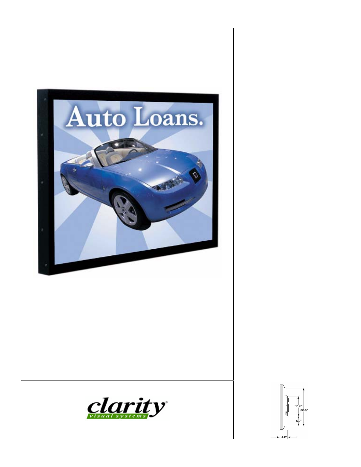
1.1 What are the Main Features of Bay Cat?
Flat screen, long backlight (lamp) life (60,000 hours). Portrait or Landscape orientation
Bay Cat is a 46" LCD display that can be wallmounted or mounted on a stand. The display can be
portrait or landscape.
Landscape
Portrait
Bay Cat is only 3.9" deep. It’s aspect ratio is 1.77
(16:9). It’s native resolution is HD (1920 × 1080). It
accepts a wide range of input pictures from VGA to
UXGA in either analog or digital (DVI).
For video it accepts NTSC, PAL, and SECAM as
composite or S-Video.
Most important, it is easy to set up and adjust.
RS232 Protocol
RS232 control for Bay Cat is available. The
instructions for this protocol are in a PDF file on
Clarity’s website:
www.ClarityVisual.com.
1. In the upper line of the home page, click on
2. Click on the lower blue
LOGIN NOW button for
LOGIN.
specifiers and end-users.
3. Your login name is “tech”.
4. Your login password is “help”.
5. Click on the Bay Cat section.
6. Click on the RS232 instructions. Be sure you get
the instructions for Bay Cat RS232, document
number 070-0146-xx.
Temporary Image Retention
Burn-in causes the screen to retain an image
essentially forever, with little or no way to correct the
problem. Bay Cat does not experience burn-in, as
plasma displays do.
However, Bay Cat’s can experience temporary
image retention. This can happen when a still
image—particularly one with high color contrast—is
displayed for an extended period, usually over an
hour.
To avoid the problem of image retention, use Bay
Cat to showing moving images, or still pictures that
change regularly.
If image retention has occurred, it will be easiest to
see when displaying the Gray Test Pattern.
If this happens, use the internal Test Pattern to
display a black screen. Research at Clarity has shown
that displaying a black image, or turning off the AC
power, is the quickest way to dissipate the temporarily retained image.
A black image is available from the Test Patterns
menu.
•
New Bay Cat features
• EDID can be set to Analog or Digital monitor for
easier Plug-and-Play operation. You can also
download a customer EDID through RS232
• Lock Mode is the Picture menu automatically
deselects all the Auto Setup options, preventing
the Bay Cat from searching for other modes
unnecessarily.
• Backlight sensors on both backlights lets you
know their status.
• Three preset color temperature setting were added
to the Color Balance menu for quick and easy
changes. The standard Color Balance menu can be
used to set custom color values.
• Message In Picture (MIP) is a method of showing
brief messages on the screen on top of whatever
pictures are currently displayed. The messages can
take any of seven forms from full screen bulletins
to what looks like sticky notes. MIP is described in
a separate document available on Clarity’s website:
Go to www.ClarityVisual.com
Click on
Click on lower, blue
User name: tech
Password: help
Look in Technical Resources under Bay Cat.
LOGINin upper right banner
LOGIN NOW button
2
Page 13

3
Page 14

1.2 You Should Have These Accessories
Standard accessories
• 1 DVI to 15-pin D-sub adapter (DVI to VGA)
•1 power cord
•1 VGA cable
• 1 remote control
•this User Guide
• Wall Bracket, with CATLOCK™ and locking tool
Optional accessories
• Adapter Plate, WAL-4025-00, with hardware
The Adapter Plate comes with 4 nuts and 8 metric
screws. The 4 nuts hold the Wall Bracket to the
Adapter Plate.
The Adapter Plate can be bolted to a wall.
Or the Adapter Plate can be screwed onto an NEC
plasma monitor display stand using the 8 metric
screws.
4
Page 15
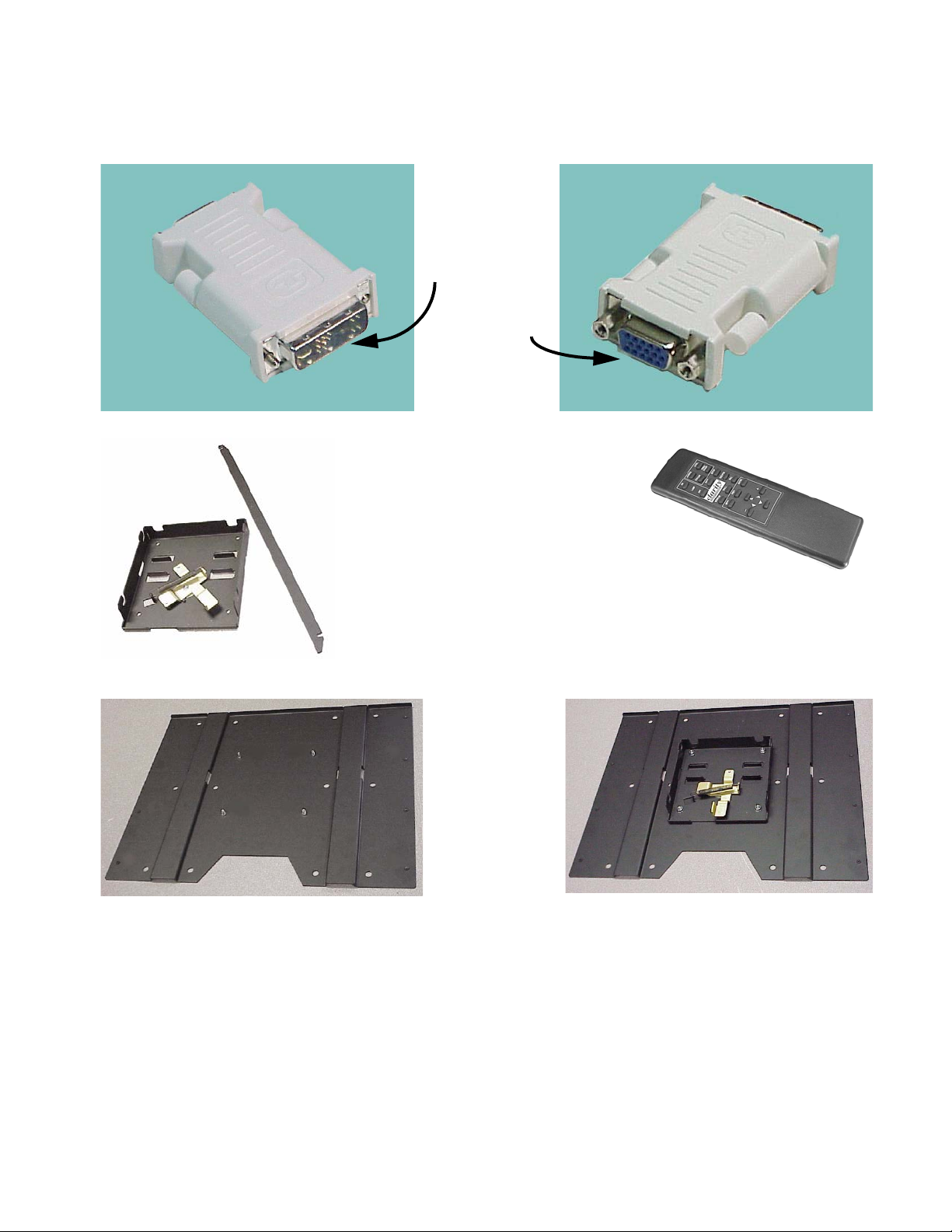
Standard accessories
Two views of the DVI
to 15-pin adapter.
DVI male connector
VGA female
connector
Remote controlWall Bracket with lock and lock-
ing/unlocking tool
Optional accessory
Adapter plate, WAL-4025-00, optional.
Attaches to a wall or to an NEC plasma display bracket.
Adapter plate after you install the Wall
Bracket on it.
5
Page 16
1.3 Safety for You and Bay Cat
This list of safety warning and caution notes isn’t very long. Reading it could save you from getting an
electric shock.
This display was designed with safety in mind. However, if you don’t heed the safety warning and cautions, you could get hurt. The safety warning are on
stickers in various places in and on the display. They
are reproduced on these pages so you can see them all
at once.
There are some other times you should be know
relating to safety:
WARNING
Wall mounts must be secure.
If the displays are hung on a wall, the wall must be
strong enough to hold them. Each display unit weighs
about 71.2 lbs. (32 kg). Simply mounting it to wallboard or wall paneling won’t be adequate or safe. The
mounting method must be capable of holding 5 times
this weight, 265 lbs. (120 kg) for each display unit.
CAUTION
The screen could be damaged by heavy pressure.
Bay Cat screens are protected with a cover glass to
protect the LCD.
Some Bay Cats are shipped, at customer request,
without this protective glass. In these, the LCD is not
protected. Slight pressure on the LCD will cause distortion of the image. Heavier pressure will cause permanent damage. Bay Cats of this type should be
mounted where viewers cannot touch the screen.
WARNING
The backlight contains mercury.
The backlight is 40 mercury vapor fluorescent
lamps. These cold cathode fluorescent lamps behind
the LCD panel contain a small amount of mercury
(112 mg in each lamp). Follow local ordinances and
regulations for disposal.
6
Page 17

7
Page 18

8
Page 19

2 Installing
2.1 What You Will Do … 10
2.2 Installing the Bay Cat Wall Bracket … 12
2.3 Hanging the Bay Cat on the Wall Bracket … 14
2.4 Connecting Power … 16
2.5 Connecting Picture Sources … 18
2.6 Connecting RS232 Communication … 20
9
Page 20

2.1 What You Will Do
The following list is for reference only. See the individual pages (in parentheses) for detailed information about how to proceed.
Installing
1. Installing the Bay Cat Wall Bracket (12)
2. Hanging the Bay Cat on the Wall Bracket (14)
3. Connecting Power (16)
4. Connecting Picture Sources (18)
5. Connecting RS232 Communication (20)
Configuring
1. Quick Start (24)
to plug it in and go.
For more precise configuration, look at these
detailed instructions:
2. Selecting the Picture (30)
3. Adjusting Levels, Computer Sources (36)
4. Adjust Levels, Video Sources (38)
5. Adjusting Sharpness (40)
6. Aspect Ratio (44)
7. Advanced Options (50)
10
Page 21

11
Page 22
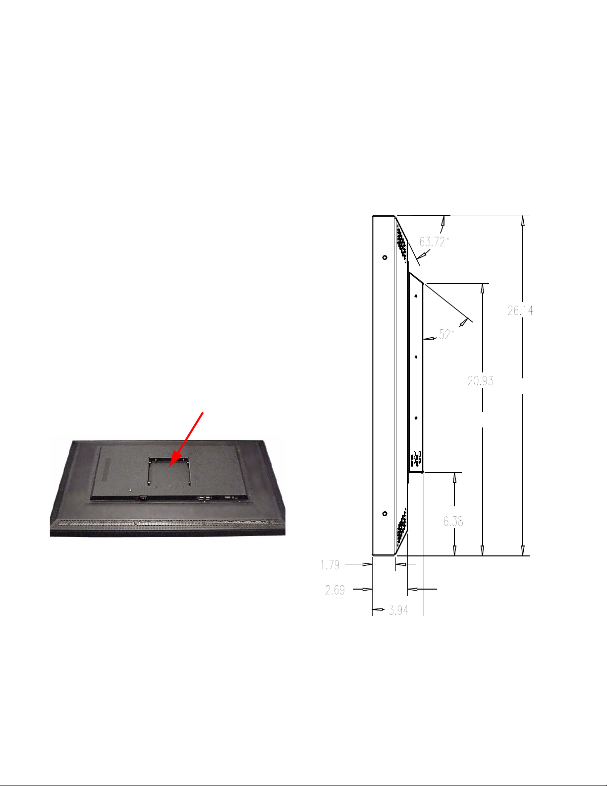
2.2 Installing the Bay Cat Wall Bracket
The Bay Cat hangs on its wall bracket in either landscape or portrait orientation. All dimensions are in
inches.
Installing the wall bracket
The wall bracket comes with each Bay Cat. The
adapter plate is optional. See picture in “You Should
Have These Accessories” on page 4.
Using hardware you supply, bolt or screw the wall
bracket to a wall. Be sure to bolt or screw to structural
elements of the wall, not just the wall board or drywall. The Bay Cat weighs 71.2 lbs. (32 kg). The
mounting method you use must be capable of holding
five times this weight (356 lbs., 160 kg).
The outer mounting holes are on 16" centers.
Ventilation
The Bay Cat needs no space to the rear for ventila-
tion. However, like all electronic devices, it does produce some heat. The space above the display should
provide enough space so that heated air can get away.
This means you should not mount it into a sealed
space with nowhere for the heated air to escape.
This space at the rear of the Bay Cat will be
occupied by the wall bracket when the display is
hanging on a wall.
Portrait or Landscape
The wall bracket always mounts the same way,
whether the displays will be hung as portrait or landscape. The hooks on the wall bracket should always
have the open part facing upward, as shown in the
drawing.
12
Page 23
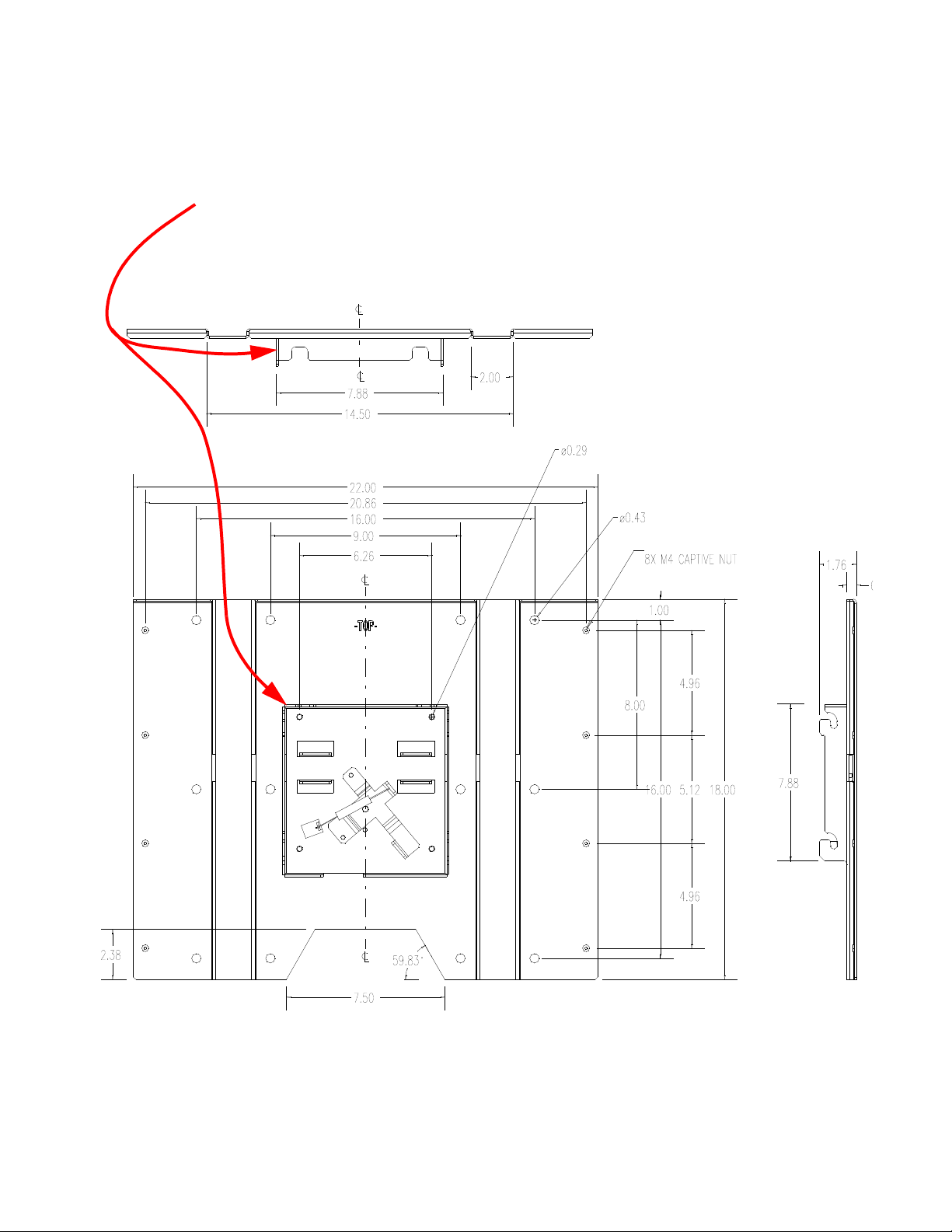
Diagram of Wall Bracket with Adapter Plate, WAL-
4025-00, an optional accessory. (See “Optional accessories” on page 4)
•The Locking Wall Bracket does not have the large
back plate. It consists of the square, open box with
the locking mechanism. This Locking Wall
Bracket with CATLOCK™ is a standard accessory.
13
Page 24
2.3 Hanging the Bay Cat on the Wall Bracket
The locking system for the Bay Cat wall bracket prevents the display from jumping off the bracket during earth tremors, and it helps deter theft.
Two-person job
The Bay Cat weighs just over 71.2 lbs. (32 kg).
Always have two persons hang the display on the wall
bracket.
Two orientations
The Bay Cat hangs in either landscape or portrait
orientation. The small black square shows the position of the AC power receptacle. The gray rectangle
shows the position of the picture connectors.
Landscape
The Bay Cat will not rotate the picture. The source
(computer) must rotate the picture. The Bay Cat can
rotate the menus, so the internal menus will be upright
with either orientation.
Hanging the display
Before you hang the first display, practice using the
lock lever to open and close the locking mechanism.
Portrait
Locking and unlocking
This end of the locking tool
works from below the wall
bracket.
This end of the locking tool
works from the sides of the
wall bracket.
After the display is hung, the connectors for video and
power are a little difficult to see. Some installers
connect power and video cables just before hanging
the display.
1. Be sure the locking lever is in the open position.
The tab on the lever should not protrude below
the bottom of the box.
2. Using two persons, lift the display so the power
receptacle is at the bottom for landscape hanging.
For portrait orientation, the power receptacle will be on
the left, looking from the front.
3. Hang the display in the hooks. Pull forward on
the display to see that it is properly in the hooks.
4. Use the locking tool to lock the display onto the
wall bracket. To see if it is locked in place, try to
lift the display. If it won’t lift, it’s locked.
14
Page 25
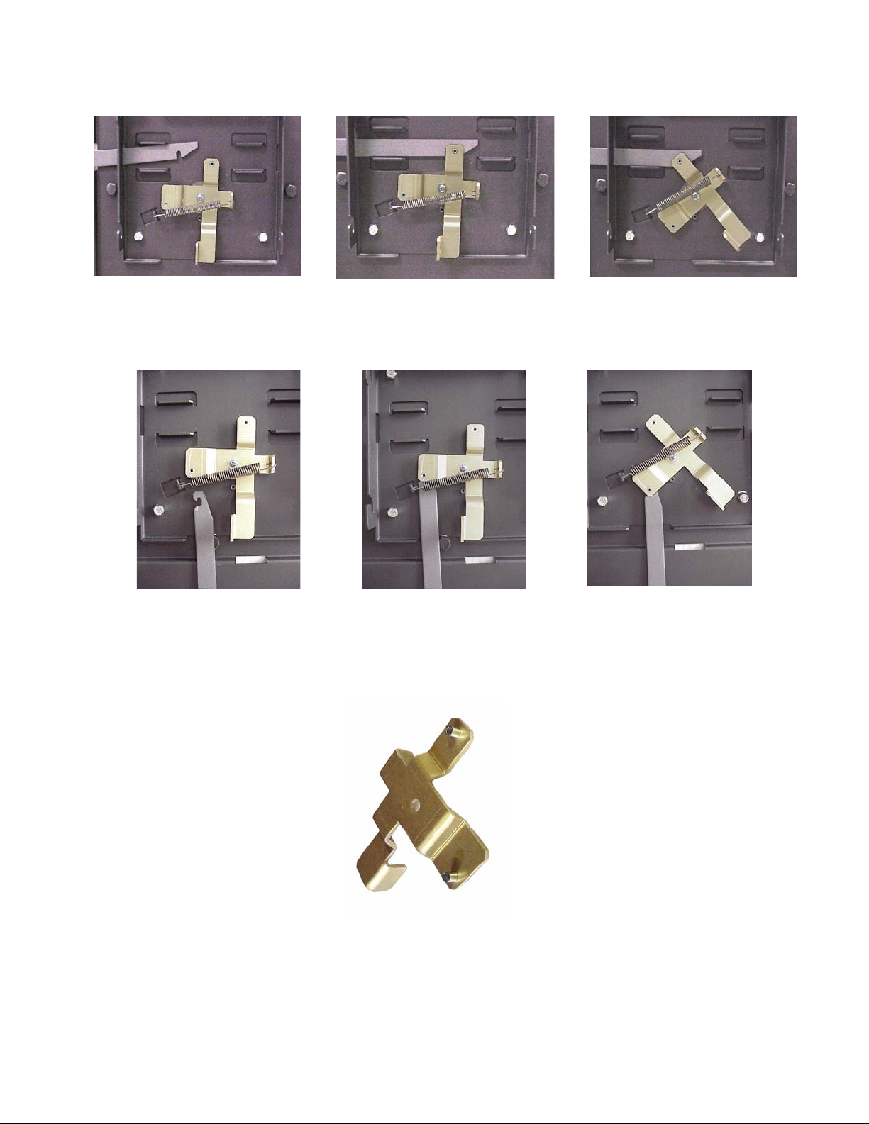
Unlocking from the side: Slide the tool in from the side. It will
ride up over the lock and catch it. Pull the lock back to unlock.
Unlocking from the bottom: Slide the tool in from the bottom, keeping the open side of the hook to the left, as shown.
Catch the lock and pull down.
Back side of the locking lever, showing
the two pins that the tool hooks onto.
15
Page 26

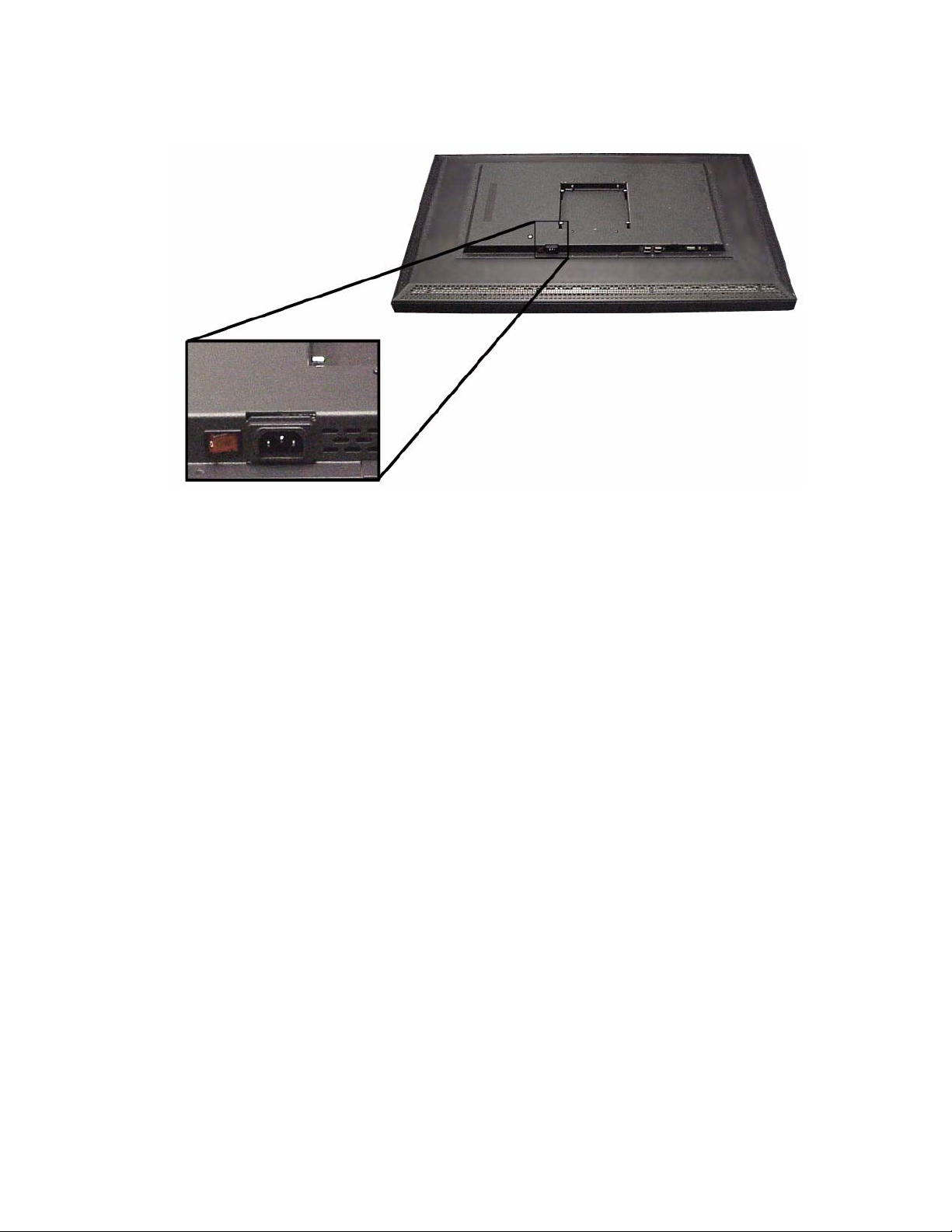
2.4 Connecting Power
Bay Cat accepts 115 VAC and 230 VAC with no manual switching.
Plug the power cord into the receptacle on the rear of
the Bay Cat. Plug the other end into a good source of
AC power.
When ready, turn on the power switch.
Normal operation
It is normal to leave the power connected and the
power switch on all the time and turn the backlight
on and off as desired.
16
Page 27
17
Page 28

2.5 Connecting Picture Sources
Digital and analog computer pictures share a common connector
Computer sources
Connect computer pictures to the DVI-I connector.
This is the standard DVI digital connector, but you
can convert it to a 15-pin D-sub for analog computer
pictures with the supplied adapter.
Computer sources are RGB. Later you will set the
Colorspace to RGB in the Picture menu.
Video sources
Connect composite video pictures to the RCA connector.
Connect S-Video pictures to the S-Video connector.
Both connectors accept NTSC, PAL or SECAM
video sources.
If Bay Cat is shipped to a destination outside the US,
the video inputs are disabled.
YPbPr sources
Component video sources, such as those provided
by some DVD players, should be connected to the
15-pin connector (through the adapter on the DVI
connector).
Most DVD players have red, green, and blue RCA
connectors for component video output. There is
available a cable with three BNC connectors on one
end (red, green and blue) and a 15-pin connector on
the other.
Therefore, to get from a DVD player to a Bay Cat,
you will need the following parts, listed from DVD to
Bay Cat:
1. RCA male to BNC female adapter, 3 each
2. Cable with BNC on one end, 15-pin VGA connector on the other
3. 15-pin to DVI adapter (supplied)
It may be necessary to select Analog or Digital in the
EDID menu.
The Colorspace in the Picture menu will be set to
YPbPr to see the colors correctly.
Macrovision, a proprietary method of encrypting DVDs
so they cannot be copied, is not supported for YPbPr
component sources. It is supported for composite and
S-Video inputs. If you can’t see a DVD movie, try the
composite or S-Video outputs of the DVD player.
YPbPr supports both progressive and interlaced
scanning.
18
Page 29
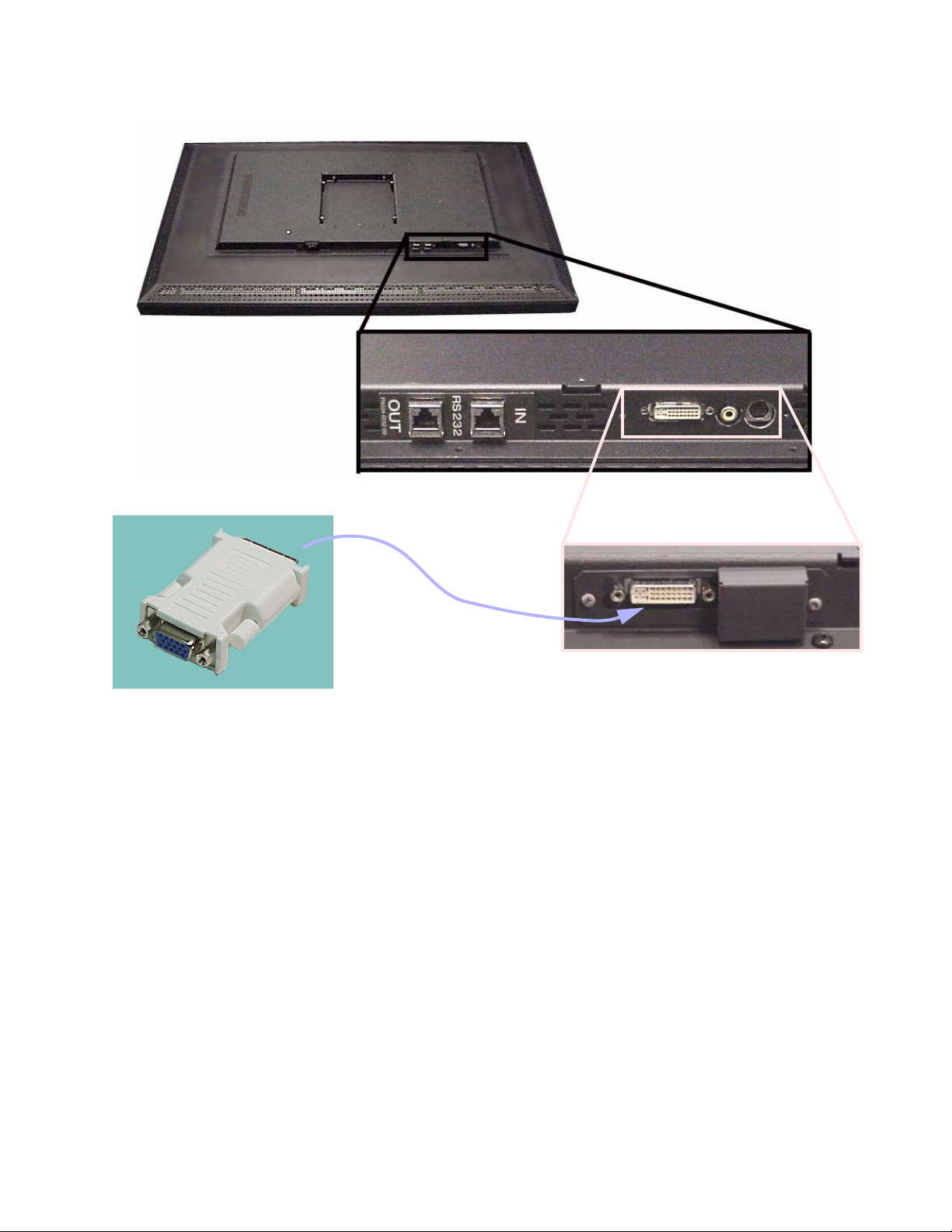
This adapter, supplied in the
accessories, converts the DVI
input connector to a 15-pin VGA
connector.
If the Bay Cat is shipped outside the
US, the video inputs are disabled.
19
Page 30
2.6 Connecting RS232 Communication
RS232 control is not necessary for operation, but it is a convenient way to control Bay Cats from a distance.
RS232 communication allows a computer to control
one or more Bay Cat displays using the computer’s
serial port. Almost everything you can do with the
remote, you can do with RS232 commands. Plus, you
can send inquiries to the Bay Cats and find out the
current settings and values.
To connect a computer to the first Bay Cat, use an
adapter on the computer’s serial port connector to
convert this to an RJ45 connector.
1. Obtain an adapter that has a female 9-pin connecter. It not be wired.
2. Wire it as shown in the illustration and table on
the opposite page. Only three wires are required.
Clip off the other wires, or tuck them into the
connector body.
Connecting for RS232 control
Use Cat-5 cable to connect from the computer
(with the adapter in place) to the first Bay Cat’s
RS232 In connector.
From the first Bay Cat, connect RS232 Out to the
next Bay Cat’s RS232 In. Continue in this way until
all Bay Cats are in the loop.
The order of Bay Cat is the loop does not matter.
As an example, suppose we have 10 Bay Cats in
one area divided into two groups. We might set the
ID s of the Bay Cats like this:
Group ID Unit ID
11
12
13
14
15
21
22
23
24
25
With this scheme, we have four ways to address
these Bay Cats:
RS232 IDs
Each Bay Cat in the loop must have a unique
RS232 ID. Open the Serial Port Settings menu for
each Bay Cat.
Set the Group ID and the Unit ID so that the combined ID is unique for each Bay Cat in this RS232
loop.
Addressing Bay Cats
Part of the RS232 command will be an address.
This address may take several forms.
20
Typ e of
Addresses
13
24
etc.
**
*5s
2*
Affect on Bay Cats
Only the specific Bay Cat addressed
will obey the command. Also, the
Bay Cat will respond to the host
computer.
All
Bay Cats in this RS232 loop will
obey the command
Both the
“5” will obey this command
All five
obey the command
Bay Cats whose IDs end in
Bay Cats in Group 2 will
A complete list of all commands is given in
“RS232 Control for Bay Cat”, document 070-0120,
available from Clarity’s website:
www.clarityvisual.com
Click on
LOGIN in the top banner.
Page 31

Click on the lower, blue LOGIN NOW button
Use the name: tech
Use the password: help
Find Bay Cat tech support.
Open or download “Bay Cat RS232 Programming
Guide.”
The wiring shown for this
adapter is correct for
straight-thru network
cables.
18
RJ45 looking into the
socket.
1
23
4
5
6798
Yellow w i r e pi n 3
Black wire pin 2
Green wire pin 5
RJ45 9-pin
63
55
32
21
Page 32

22
Page 33

3 Adjusting and Maintaining Bay Cat
3.1 Quick Start … 22
3.2 Operating the Bay Cat … 24
3.3 Manual Selection and Adjustments … 26
3.3.1 Selecting the Picture … 28
3.3.1.1 Auto or Manual Mode Selection … 30
3.3.1.2 EDID: What It Is and How It Works … 32
3.3.2 Adjusting Levels, Computer Sources … 34
3.3.3 Adjust Levels, Video Sources … 36
3.3.4 Adjusting Sharpness … 38
3.3.5 Position … 40
3.3.6 Aspect Ratio … 42
3.3.7 Adjusting Color Balance … 44
3.4 Diagnostics, Test Patterns … 46
3.5 Advanced Options … 48
3.5.1 Miscellaneous Options … 50
3.5.2 Backlight Control and Status … 52
3.5.3 Force Analog Mode … 54
3.5.4 Serial Ports Settings … 56
3.6 Cleaning the Screen … 58
23
Page 34

3.1 Quick Start
After you select the picture source, most of the rest of setup is automatic, although you can override
the automatic settings and adjust anything manually.
Selecting the source means choosing the connector
where the picture is coming in. In the case of the
Analog/Digital connector, it also means choosing
between Analog and Digital.
There are three input connectors:
• an analog/digital computer connector
• an S-Video connector
• a composite video connector
Quick start
Connect power and turn on the power switch, which
should light. The backlight (lamp) will come on automatically. If the power was already on, and the backlight is off, press the remote
ON button.
1. Aim remote control at the lower left corner of the
Bay Cat and press
SOURCE on the remote. The Bay
Cat will now look at each of the three connectors
and stop on the first one that is receiving a valid
picture.
If this is successful (it may take 10 seconds)
stop here.
If you have several sources connected, press
SOURCE again to go to the next one with a picture.
If you get no picture or have other trouble, read
the rest of these steps.
If you see no picture …
• Check the source by connecting it to another type
of display. If the source is a laptop, maybe it has
timed out and the screen is blank. Did you enable
the VGA output on the rear of the laptop?
• Check the power switch near the AC power cord.
It should be lit.
• The IR receiver for the remote is a small hole in
the lower left corner of the display. Be sure the
remote is aimed toward it. (In Portrait orientation
the IR receiver is in the upper left corner.
Landscape
Portrait
If the source is component video, you will have to
manually change the Colorspace to YPbPr. Otherwise
the colors will be wrong.
2. Press MENU. The Main Menu should appear.
3. Select Picture with the up-down arrow keys on the
remote and press
ENTER. This will open the Pic-
ture menu.
4. With the left-right arrow keys, select the input
connector you want:
a) Analog RGB (usually computer sources, VGA
thru UXGA)
b) Digital RGB (DVI)
c) Comp Video
d)S-Video
If the source picture is component video (YPbPr), select
the Analog RGB
5. Press ENTER. The Bay Cat will immediately display the picture. Within a second or two the Bay
Cat will analyze the picture and adjust to it.
24
• Check whether EDID is set to Analog or Digital.
(See “EDID: What It Is and How It Works” on
page 34.)
About the remote
The remote control operates with IR (infra-red)
signals going to the IR receiver. The receiver is in the
lower left corner of the screen bezel behind a small
hole.
(Later, to prevent accidental adjustment of the display, cover this hole with a small square of black
tape.)
A quick reference for all the remote buttons is
found in “Remote Control Buttons” on page 78.
Page 35

Burn in vs. image retention
Burn-in causes the screen to retain an image
essentially forever, with little or no way to correct the
problem. Bay Cat does not experience burn-in, as
plasma displays do.
However, Bay Cat’s can experience temporary
image retention. This can happen when a still
image—particularly one with high color contrast—is
SOURCE button
displayed for an extended period, usually over an
hour.
If this happens, use the internal Test Pattern to
display a black screen. Research at Clarity has shown
that displaying a black image, or turning off the AC
power, is the quickest way to dissipate the temporarily retained image.
The FREQ/PHASE button opens
the Picture menu directly.
25
Page 36

3.2 Operating the Bay Cat
The Bay Cat has a cache which saves the last ten source settings.
To change sources (input connectors)
Press the
will look for the next connector that has a picture
coming in, select that one, and auto adjust to it.
Or open the Picture menu and select the source
with the left-right arrow keys.
SOURCE button on the remote. Bay Cat
corner. You can also disable and enable IR command
processing with an RS232 command.
To save settings
Settings (position, aspect ratio, brightness/contrast, color balance) are saved automatically 5 seconds after you make a change. The system caches the
last tens settings. Whenever a picture is shown from
a new source with the same resolution as a previous
picture, the system recalls the previous settings
rather than readjust everything. This happens regard-
less of the check marks in Auto Adjust Options. (See
also “Auto Adjustment Options” on page 51.)
For example, suppose you display an NTSC picture
in the composite input and set the Aspect Ratio and
Position to your liking. Then you feed in a composite
PAL picture and set a different Aspect Ratio and a different Position. If you then feed in a new NTSC picture, the previous NTSC picture’s settings for Aspect
Ratio and Position will be used.
To “disable” the remote control
To prevent unauthorized use and adjustment of
the Bay Cat, either hide the remote, or put a small
piece of tape over the IR received hole in the lower left
26
Other manual operations
Subject Page
Aspect Ratio 44
Auto Adjustment Options 51
Color Balance 46
EDID settings
Input Level adjustments 36
Menu position, rotation 50
Picture, selecting 30
Position 42
Test Patterns 48
34
Page 37

27
Page 38

3.3 Manual Selection and Adjustments
Manual and semi-automatic adjustments are better for most things. Frequency and Phase are all right
when done automatically.
The manual adjustments fall into several categories.
The illustrations below and opposite show the menus
The appearance of the Picture menu
depends on the selected source.
For details, see “Selecting the Picture” on page 30
The S-Video menu looks the same
as the Comp Video menu.
and indicate where to go for further information on
them.
28
For details, see “Position”
on page 42
Page 39

For details, see “Aspect Ratio” on page 44
For details, see “Adjusting Levels,
Computer Sources” on page 36
For details, see “Diagnostics, Test Patterns” on page 48
For details, see “Advanced Options” on page 50
29
Page 40

3.3 Manual Selection and Adjustments
3.3.1 Selecting the Picture
Selecting the source (picture) manually is usually quicker than using the SETUP button.
Selecting the picture is really selecting the input connector. There are three of these connectors:
• Analog/Digital Computer
•Composite Video
•S-Video
Computer sources
Use Computer connector for either analog inputs,
the type we’ve used for years with computers, or digital inputs, the newer DVI standard. Either of these
accepts pictures of the following common standards
as well as many, many others:
Typ e Re so lut io n
VGA 640 × 480
SVGA 800 × 600
XGA 1024 × 768
SXGA 1280 × 1024
WXGA 1280 × 768
UXGA 1600 × 1200
HD1920 1920 × 1080
VESA 640 × 400
Component video sources
Analog sources that are YPbPr instead of RGB are
selected in the Picture menu with “Analog,” but the
Colorspace must be changed to YPbPr Component
Video.
DVD sources
DVD players have composite video and S-Video
outputs, and they sometimes have component video
outputs from three RCA connectors. The component
output is in YPbPr form. You must select YPbPr for
the Colorspace item in the Picture menu. See “YPbPr
sources” on page 18.
Composite Video and S-Video
These two inputs accept NTSC, NTSC at 4.43/60,
PAL, PAL at SECA M video p ictu r es.
To s e l e c t t h e s o u r c e
1. After the display is on, press
This opens the Main Menu.
2. With Picture highlighted, press
3. Use the left-right arrow keys on the remote to
select the type of source, and press
MENU on the remote.
ENTER.
ENTER.
a) Analog RGB
b) Digital RGB
c) Comp Video (composite video)
d) S-Video (Y/C video)
4. Close the menu by pressing
ENTER, or let it time
out.
The resolution or type of source picture currently
coming in is displayed on the line just below Source.
This is grayed out because you can’t adjust it.
Analog sources
With the Analog RGB sources you can adjust Frequency, Phase, Brightness and Contrast and choose
the amount of Sharpness you want the displayed picture to have.
The fastest, easiest way to adjust Frequency and
Phase is to press the
SETUP button. If Do Frequency
and Do Phase are checked, both these adjustments
are completed in one second.
Manually adjusting Frequency and Phase can be
accomplished if you have a checkerboard pattern on
your computer. A checkerboard is a pattern in which
alternate pixels are black and white. It is the most difficult picture for the electronics to handle.
Making a checkerboard in Windows
1. Start the Paint program.
2. In the menu bar, select Image > Attributes.
3. Choose the Width and Height of the resolution in
pixels. In Colors, choose Black and White.
4. Click OK and answer Yes in the next box.
5. Near the bottom, find the row of gray shades that
starts with white. Counting the white chip is “1”,
click chip number “9”.
6. Click the spilling paint jar from the tools at the
left.
7. Click in the picture area. This picture now has
black and white pixels alternating.
Manual adjusting Frequency and Phase
1. Display a checkerboard pattern from the computer that will be used for program material.
2. Press
MENU, select Picture, and press ENTER.
3. Select Frequency. Use the right-left buttons to
change the frequency up and down to eliminate
vertical banding in the picture.
30
Page 41

4. Select Phase. Use the right-left buttons to elimi-
nate horizontal streaking.
5. Exit all menus.
Digital RGB
There are no adjustments for Digital RGB sources.
Video sources
With Composite and S-Video sources you can
adjust Brightness, Contrast, Saturation and Hue. Saturation and Hue are best adjusted using a color bar
pattern, if one is available from the source.
Scaler Sharpness is similar to the Sharpness control for Analog RGB sources. Video Sharpness is a filter applied to the picture before it gets to the Scaler
Sharpness filter
Choose Analog RGB, press ENTER, and you get this kind
of menu.
Choose Digital RGB, press
of menu.
Choose Comp Video or S-Video, press
get this kind of menu.
ENTER, and you get this kind
ENTER, and you
31
Page 42

3.3 Manual Selection and Adjustments
3.3.1 Selecting the Picture
3.3.1.1 Auto or Manual Mode Selection
Sometimes the automatic mode selection doesn’t get it right. If this happens, you can force the mode
manually. This works for Analog RGB sources only.
Auto mode selection
•Press
•Press
There are potential problems with any automatic system. Sometimes you may switch to another analog
RGB source that is very close to the previous one. Bay
Cat may not detect the difference and use the old
mode.
SETUP to make the Bay Cat automatically
readjust itself to the current picture.
SOURCE to make the Bay Cat look for the
next connector with a valid signal.
Manual mode selection
If the Bay Cat has trouble with an analog RGB
source, try forcing the mode manually.
Forcing the mode works only with RGB sources that
have H&V sync. It does not work with composite sync
or sync on green.
First, you must know the mode of the analog RGB
source. Look up this mode in the table, opposite, and
open the Force Analog Mode menu.
1. In the menu, be sure Enable Force Mode is not
checked.
2. Select the Select Mode Number line and use the
+ \ – keys to choose the mode number found in
the table. (See Analog RGB Modes table on
page 94.)
The resolution and vertical refresh rate show in the
menu in the current resolution, not the resolution of the
mode number. These numbers do not change until you
check Enable Force Mode.
32
3. Arrow down and press ENTER to force the Bay Cat
to use this mode.
Bay Cat will use this forced mode for all analog RGB
sources until this line is unchecked. When
unchecked, the automatic system will start again.
Page 43

33
Page 44

3.3 Manual Selection and Adjustments
3.3.1 Selecting the Picture
3.3.1.2 EDID: What It Is and How It Works
EDID is the name of a method computers use to determine the characteristics of the computer monitor.
EDID stands for Extended Display Identification
Data. It is the system behind Plug and Play. But just
knowing its name doesn’t tell you how it works.
EDID is a block of 128 bytes of data residing in a
monitor that contains information about …
• the manufacturer,
•the product ID,
• whether the monitor is analog or digital,
• video timings [resolutions],
• and color capability.
How EDID works
When a computer with EDID capability boots up,
it reads the EDID data in the monitor it is connected
to. It stores this data in the Registry (in Windows™)
where it is available to the video card.
Different video cards use this information in different ways. Many video cards will not send video
with resolutions that are not listed in the monitor’s
EDID.
timings) than can be store in a data block of only 128
bytes. Clarity displays are capable of hundreds of resolutions, but the EDID block has room to store only
dozens.
This means that some video cards will not put out
certain resolutions, even though the connected Clarity display is capable of handling them. If the resolution you want to use is not listed in the Clarity
EDID, and the video card won’t list that resolution
unless it is seen in the EDID, what can you do?
A possible solution is to uncheck the Plug and Play
box in the Miscellaneous menu (shown below). This
causes the EDID to use an incorrect CRC checksum.
Some video cards will see the incorrect checksum,
assume the data is corrupted, and fall back on a
default set of timings, which may include the one you
want.
Other cards may not bother to look at the checksum and limit the resolutions to those in the display’s EDID.
Analog or digital
EDID works in either analog or digital mode, but
the Bay Cat must know which to use. You do this in
the Miscellaneous menu.
This dialog shows a setting of 1152×872 for the
1st monitor. If the #1 monitor were not capable of
this resolution, some video cards would not show
1152×872 in the dialog box.
EDID too small for Clarity displays
One problem with this system is that Clarity displays are capable of many more resolutions (video
34
When EDID doesn’t work
• There is no point in changing the refresh rate in
the Display > Settings tab > Advanced menu.
The Clarity display has a fixed refresh rate of 60
Hz. It will handle other refresh rates, but the
native refresh rate it fixed. The electronics system
Page 45

changes the incoming video to the display’s fixed
refresh rate.
• Be sure you the EDID for DVI/Analog settings is
correct. Some video cards with both analog and
digital outputs use only one of them, the one corresponding to what the card read in the EDID.
The other output from the card will have nothing.
• Uncheck the Plug and Play box and reboot the
computer.
• If you must use a video resolution that is not displayed in the Settings > Control Panel > Display
> Settings tab, and that resolution is listed in
“Tables of Modes for Analog Inputs” on page 94,
try unchecking the Plug and Play box. If that does
not help, you may have to contact the manufacturer of the video card for help.
35
Page 46

3.3 Manual Selection and Adjustments
3.3.2 Adjusting Levels, Computer Sources
This section applies to Analog RGB (computer) pictures only. The Levels are best adjusted semi-automatically.
Why adjust levels?
For analog RGB pictures the levels for black and
white vary from one computer to another, or from
one video processor to another. They even vary
between video output from a multiple-output video
card in a computer.
Your pictures will not look their best on Bay Cat
until you adjust for these differences. This is not
about adjusting color or contrast. It’s about telling the
Bay Cat what the computer or processor means by
black and by white.
Semi-automatic adjustment
1. From the computer source, display an all-black
picture.
2. Press
3. Select Input Levels and press
4. In the Input Levels menu, select Auto Black Level
5. From the computer source, display an all-white
6. In the Input Levels menu select Auto White Level
MENU, select Picture, and press ENTER.
ENTER.
and press
ing…” until the process is complete.
picture.
and press
pear.
ENTER. This menu line says “Work-
ENTER. Wait for “Working…” to disap-
the computer that will be used for the program material.
Adjusting levels with your laptop, then connecting to
the “real” computer will not do a proper job.
Next, adjust Contrast (gain) until the Image Maxi-
mums just go to 255. Again, do not push it up after
the maximum is 255. Just touch the 255 point.b You
must adjust Brightness first, Contrast second.
If the three colors are not all at 255 (or 254), adjust
them separately.
Full automatic adjustment of levels
This sounds like the ideal solution, but it isn’t.
When the Do Black/White Levels box is checked in
the Auto Setup Options menu, the Bay Cat adjusts to
the brightest and darkest pixel in the picture. This
does not work well because:
• some pictures do not contain a pure white pixel;
• some white pixels contain “spikes,” which makes
them seem brighter than they really are, resulting
in incorrect settings.
Black Level must be done before White Level. The
black and white pictures must come from the real
source. It doesn’t help to do this with a laptop, then
plug in the “real” computer for the program.
That completes the levels adjustments. If you have
more than one computer or other analog RGB source,
as might come from a switcher, you should do this for
each source.
Adjusting levels for computer sources manually
Send a picture to the Bay Cat that has something
completely black and completely white in it. In the
Advanced Levels menu, adjust Brightness (offset) up
and down until the values in Image Minimums just go
to zero or one. Do not push it down after the minimum is zero. You want to just touch the zero point. If
all three colors are not at 0 (or 1), adjust them separately in the same way.
You cannot make these adjustments using the internal
Test Patterns. The black/white picture must come from
36
Page 47

37
Page 48

3.3 Manual Selection and Adjustments
3.3.3 Adjust Levels, Video Sources
Video sources are adjusted best if a color bar test pattern is available from the video source: the DVD or
VCR player. If not, you will have to adjust by eye and the “feel” of the picture.
Adjusting with color bars
1. If possible, use a color bar pattern from the video
source you will use for the program material. You
cannot use the color bar from the Test Patterns
menu.
2. In the Picture menu, check Blue Only. You should
see only the alternate color bars, all of them blue.
3. Adjust Saturation to make the outer two color
bars match. Match them in brightness; they will
already match in color.
4. Adjust Hue to make the inner two color bars
match.
5. Uncheck Blue Only
When a video source is selected, Auto Setup Options is
not available. Adjustments must be made manually.
6. If the color bar pattern has a pluge, you can use it
to adjust Brightness.
1. Choose pictures that have blacks and whites represented as well as a variety of colors.
2. Adjust Contrast, Brightness, Saturation and Hue
on one Bay Cat until it looks satisfactory.
3. Adjust all the other Bay Cats in the wall so they
have the same values for Contrast, Brightness,
Saturation and Hue as the first Bay Cat.
Pluge
Adjust Brightness so you cannot
see the different between these
two marks,
but you can see the difference
between these two marks.
Adjusting with any picture
This procedure must be done after you adjust color
balance (page 46).
38
Page 49

Saturation
Hue
Match
Adjust Saturation so the outside bars
match when Blue Only is checked.
Match
Match
Match
Adjust Hue so inside bars match
when Blue Only is checked.
39
Page 50

3.3 Manual Selection and Adjustments
3.3.4 Adjusting Sharpness
The Sharpness control has two types of sharpness settings, one for in the Picture menu which adjusts
the scaler, and one in the Video Adjustments menu, for video sources only, which is in the video
decoder.
Sharpness for computer sources
If you are using analog or digital computer pictures
as sources, you will use only the Scaler Sharpness setting in the Picture menu.
In this situation, use only the sharpness settings
beginning with “RGB”:
•RGB Soft
•RGB Medium Soft
•RGB Normal
•RGB Medium Sharp
•RGB Sharp
RGB Normal is the default. It is essentially a
“pass thru” with no effect on the picture. Make any
adjustments to sharpness with the picture scaled,
that is, with the Aspect Ratio set the way you will use
it. Use Scaler Sharpness to reduce or eliminate any
artifacts of scaling.
The other is a slider in the Video Adjustments
menu.
Start with the Scaler Sharpness set to the Video Nor-
mal position.
• Video Soft
• Video Medium Soft
• Video Normal
• Video Sharp
• Video Sharp+
• Video Sharp++
• Video Sharpest
Set the Aspect Ratio to 1 to 1.
Sharpness for video sources
There are two sharpness controls for video sources.
One is the scaler described above, but with all the settings beginning with “Video.”
40
Adjust the Video Sharpness slider in the Video
Adjustments menu to get rid of any artifacts from the
video decoder. (Video pictures go through the decoder
first, to turn the picture into a digital form, then they
go through the scaler.)
Now set the Aspect Ratio to the one you will use in
for the program. Choose a Scaler Sharpness setting in
the Picture menu to get rid of any scaling artifacts.
Page 51

41
Page 52

3.3 Manual Selection and Adjustments
3.3.5 Position
This moves the picture image on the screen, but does not move the menus.
Position
In the Image Pan menu, the four arrow keys move
the picture.
The Horizontal Position number shows the number
of pixels from the beginning of H sync to the first
active pixel. Because there are many black pixels after
H sync, this number will not be zero when the picture is at the left border of the screen.
The Vertical Position number is the number of
lines from V sync to the first active line, so it will not
be zero when the picture is at the top of the screen.
42
Page 53

43
Page 54

3.3 Manual Selection and Adjustments
3.3.6 Aspect Ratio
The aspect ratio of any picture is its height divided by its width. H ÷ W = Aspect Ratio
The native aspect ratio of the Bay Cat screen is 1.77,
which is sometimes referred to as 16:9. This is the
HD1920 picture format.
1920 × 1080 pixels
1920 ÷ 1080 = 1.77
Many pictures do not have this aspect ratio. Standard television is 1.33 and HDTV is 1.77. Movies
from DVDs vary depending on the original film format, often 1.85. The larger the number, the “wider”
the picture seems.
When the incoming picture is a different aspect
ratio from the screen, Bay Cat gives you four choices
to make it fit. (These are “radio” buttons; you can
only choose one.)
Fill Both Ways makes the picture fit top-to-bottom
and left-to-right regardless of how this stretches or
compresses the picture.
Fill Both Ways distorts the picture, when the aspect
ratio of the incoming picture is not the same as the Bay
Cat screen, 1.66. The other three choices (below) do
not distort the picture.
Keep Aspect Ratio/ Fill One Way fills the screen
top-to-bottom or left-to-right, whichever way fits
first. If the aspect ratio of the picture is less than
1.77, such as normal TV’s 1.33, the screen will show
blank areas on the left and right.
If the aspect ratio of the picture is greater than
1.77, such as wide-screen movies of 1.85, the screen
will show blank areas at the top and bottom.
Keep Aspect Ratio/ Crop fills the screen completely
without distortion, but crops the picture on one side
or the other. If the aspect ratio of the picture is less
than 1.77, such as normal TV’s 1.33, the picture will
be cropped (chopped off) at the top and bottom.
If the picture’s aspect ratio is greater, the picture
will be cropped at the left and right sides.
1 to 1/ Keep Original Size maintains the original
size and aspect ratio of the picture. This may leave
blank areas on all four sides. For instance, a VGA picture (640 × 480) will occupy only a small area in the
center of the screen. For UXGA sources, this will crop
the picture top and bottom.
44
Page 55

These are examples of what happens to the
picture when the aspect ratio of the source
picture does not match the aspect ratio of
the display. This will be the case every time
the source picture is not HD1920, or some
other 1.77 source.
SVGA picture (800x600)
1:1 / Keep Original Size
Wide-screen pi cture, Aspect Ratio 1.85
Keep Aspect Ratio/ Fill One Way
Wide-screen pi cture, Aspect Ratio 1.85
Fill Both Ways
SVGA picture (800x600)
Keep Aspect Ratio / Fill One Way
SVGA picture (800x600)
Fill Both Ways
Wide-screen picture, Aspect Ratio 1.85
Keep Aspect Ratio / Crop
SVGA picture (800x600)
Keep Aspect Ratio / Crop
45
Page 56

3.3 Manual Selection and Adjustments
3.3.7 Adjusting Color Balance
Color Balance is used to match the colors of adjacent displays when several Bay Cats are arranged in a
wall. You may also use it to adjust the color of a single display.
For one Bay Cat only
If you have only one display, the Color Balance
controls can be used to set the color temperature of
the single display. Select Color Temperature in the
Color Balance menu and select from
• 3200K
• 5500K
• 6500K
• 9500K
Each of these selects a set of White Balance and Gray
Balances values to give the picture a warm (3200K) to
cool (9500K) appearance.
To adjust a wall of Bay Cats for Color Balance
Open the Backlight Control and St atus menu (
A
DVANCED OPTIONS > BACKLIGHT CONTROL & STATUS).
MENU >
a) Set Backlight Mode Control to Manual.
b) Set Backlight Intensity to 100%.
1. Open the Color Balance menu on all displays in
the wall. (
B
ALANCE).
MENU > ADVANCED OPTIONS > COLOR
a) Select Color Temperature at the top of the
menu and press the left or right arrow to get to
Custom.
b) Highlight Reset to Defaults at the bottom of
the menu and press
ENTER.
c) Highlight Test Pattern and use the left-right
arrow keys until it says White.
2. Do the previous steps on all Bay Cats in the wall.
3. When all displays are white, find the least bright
display in the wall. This will be the “baseline” display, and you will not adjust it. All other displays
will be adjusted to this baseline display.
Why pick the “least bright” display? Why not pick the
brightest and adjust to it? When the White value is 100,
the display is a bright as it can get. You are adjusting for
slight variations in backlight brightness.
4. Choose a display next to the baseline display and
adjust its White values (red, green, and blue) to
make it match the baseline display. Concentrate
on the center of the displays, not the adjacent
edges. (If you can’t bring theses settings down to
match the baseline, maybe you didn’t choose the
darkest display.) Do not adjust the Gray values at
this time.
5. Continue with other adjacent displays until all
the displays have the same appearance when
white. Be careful not to change the values of displays once you are satisfied with them. Cover the
remote control holes (lower left corner of bezel) to
prevent this, or turn off the menus.
The menus will automatically turn off after a time
determined in Menu Options (
Options > Menu Options > Menu Timeout). If Menu
Timeout is 0 (zero), the menus stay up indefinitely.
6. When all displays look the same for White,
choose the Gray test pattern in all displays.
7. Choose any display as the new baseline display. It
does not need to be the baseline display you used
for White.
8. Adjust all the displays in the Gray part of the Test
Patterns menu until they match the baseline display. Do one display at a time. Again, match the
center part of the picture, not the edges.
9. When all displays match in Gray, turn off all the
Test Patterns and close all the menus.
Tips for color balancing
• Removing red has the same effect on hue as
increasing blue and green together. The Color Balance menu slider bars have colored bulbs at each
end to tell you what the effect will be of moving a
color toward that end.
• Stand back from the display wall and directly in
front of it to get the overall view.
• Small changes are difficult to see at first, particularly with White. Change the value by 4 or 5 steps
to see the difference. If you are going the wrong
way, go back and move it 4 or 5 steps in the other
direction. If neither of these bring you closer to a
match, try another color.
• When you don’t know which color to change, pick
one at random and change it 3 or 4 steps. The
result will be either better or worse. If worse, go
the other way with that color. If that is also worse,
put this color back where you started and to the
same with another color. If everything you do
makes the match worse, you must be close to the
ideal point.
MENU > Advanced
46
Page 57

First press of
MISC button
Second press of
MISC button
47
Page 58

3.4 Diagnostics, Test Patterns
These are used for testing and troubleshooting
Possibly the most important test pattern is None.
This is the one that allows the source picture to show
on the screen. All other patterns block the program
picture.
All test patterns are full screen. Aspect Ratio has
no effect.
To t u r n o n a Tes t P a t t e r n
1. Press
2. Select the pattern with the up-down arrows. The
3. Press
MONITOR then press ENTER.
up-down arrows will eventually get you to the
next column.
ENTER to display the highlighted test pat-
tern.
When a Test Pattern is shown, the program picture is
blocked. To see the source picture, set Test Pattern to
None.
To t u r n o f f a Te s t P a t t e r n
1. Press
2. Select None with the up-down arrows.
3. Press
White, Red, Green, Blue, Black, and Gray all show
full screens of the color. Gray is 50%.
MONITOR then press ENTER.
ENTER.
Colors shows a rainbow of colors and a gray scale at
several levels of saturation for testing uniformity.
Fans & Diagnostic Values
This menu shows the state of the fans, whether
OK or Failed. A failed fan does not turn off the backlights.
The next two menu items are about RS232 control, showing the last packet type received and the
number of packets received thus far. Packets Received
is not reset to zero except by counting past 32,767
and rolling over to 0.
4 x 4 Checkerboard is a pattern of 16 rectangles
alternating black and white.
The Gray, Red, Green, and Blue Scales show 32- or
64-step scales. You should be able to see all the steps
clearly.
Grid shows a white background with a 4 x 4 grid of
magenta lines surrounded by a 3-pixel-wide magenta
border.
Color Bars displays a pattern of the three primary
colors and the primary combinations along with
black and white. This is similar to, but not the same
as, color bars in the television and video field. These
bars are 100% saturated.
Uniformity shows some marks on the screen where
factory measurements are made for color and brightness uniformity testing.
48
Page 59

None is the only one that does
not block the incoming picture.
Choose “None” to show the
source picture on the screen.
49
Page 60

3.5 Advanced Options
Menu Options moves the menus to other places on the screen. Auto Adjustment Options sets what
will happen automatically and what will not.
Menu Options
These controls move the menu to a different position on the screen or rotate it for Portrait orientation.
Menu Timeout is set here.
H Position moves the menus (all of them) left and
right on the screen. Use the left and right arrow keys
to increase or decrease the distance from the left side
of the screen to the left side of the menu. The number indicates the how far across the screen, in percent, the menu starts.
V Position moves the menus up and down. Use the
left and right arrow keys (on the up-down keys) to
move the menu. The number indicates how far down
the screen the menu is in percent. It is not possible to
move the menu to the bottom of the screen.
Menu Timeout determines how many seconds the
menu will stay on the screen without any activity.
Zero means the menus will not automatically disapper. The maximum time is 60 seconds. The shortest
50
possible time is 2 seconds. The default value, if you
have never changed Menu Timeout, is 10 seconds.
Menu Rotation makes the menus readable when the
Bay Cat is arranged in portrait or landscape orientation.
Menu Rotation does not rotate the picture. It only
arranges the menus so they read the same way the
picture does.
Page 61

Auto Adjustment Options
Each of the “switches” in Auto Options can be
turned on or off by selecting it (up-down arrows) and
pressing
ENTER. When the box is checked, ;, the
action will occur under these circumstances:
• When a new source is detected that has not been
detected before. (See ’About the cache’ on this page
and “To save settings” on page 26.)
• When you press the
SETUP button.
Search on lost signal occurs only when the present
signal (picture) disappears. When this happens, the
Bay Cat will look at the other connectors to find a
valid picture.
Note that searching will not happen just because
the picture goes black. Black, from video or from a
computer, is a valid picture. The signal itself (the
sync pulses) must be lost to trigger a search.
The several Do items in this menu will, if checked,
happen in these situations:
• If a new signal is acquired, either through a search
to a different connector or because source picture
changed modes, such as from WXGA to UXGA,
each of the checked items occurs in the order
listed in the menu.
•When you press the
SETUP button on the remote,
each of the checked actions occurs in the order
given in the menu.
Do Quick Black/White Levels searches for the
brightest and darkest pixels in the picture and adjusts
to these. Black and White Levels are best done semiautomatically (see “Adjusting Levels, Computer
Sources” on page 36) so leave this unchecked.
Do Frequency and Do Phase find the frequency and
phase (separately) of the computer picture and adjust
to them. This works best on a picture that has lots of
sharp changes in brightness, such as text (adjacent
white and black pixels).
Do Position centers the picture on the screen.
About the cache
The Bay Cat has a cache for storing the most
recent attributes of the pictures it displays. When a
new picture arrives that is near enough to a previous
type, it uses the stored attributes rather than automatically adjusting brightness, contrast, frequency,
etc.
For example, suppose the Bay Cat sees an analog
WXGA picture and auto-adjusts everything in the
Auto Options Menu. Then you change the Brightness
and Contrast. Then you change computers and feed
in a UXGA picture.
If you now switch back to the computer with the
WXGA picture, Bay Cat will use the Brightness, Contrast, as well as other settings, from the last time it
saw a WXGA picture.
Aspect Ratio is global, which means it applies to all
input types. It does not change when the system recalls
a memory from cache.
Setup button
The
SETUP button on the remote starts the “Do”
processes. Each Do that is checked
at a time, until all are adjustments completed.
Locking the settings
In the Picture menu, checking Lock Settings
immediately unchecks all the items in the Auto
Setup Options. This effectively locks the settings.
; will begin, one
51
Page 62

3.5 Advanced Options
3.5.1 Miscellaneous Options
This menu holds several unrelated settings.
Auto Backlight On turns on the backlight whenever
AC power is restored. This is normally checked.
Curtain Pattern determines what the screen will
show when there is no source picture. You have a
choice of several solid colors or the Clarity logo.
T urn Backlight Off With No Source saves electricity
and backlight life. When the source is restored, the
backlight turns on again.
Ignore RS232 CRC means that RS232 commands
will be accepted whether they have the correct CRC
check sum or not.
Enable Image Orbiting moves the image by one
pixel-size at a time to prevent or alleviate temporary
image retention.
When a high-contrast, still image is displayed for a
long time on Bay Cat, it sometimes happens that the
image is retained temporarily. To recover from this,
display a black picture, such as the black test pattern,
for a while until the retained image can no longer be
seen.
If still pictures are unavoidable, reduce the possibility of temporary image retention: turn on image
orbiting.
This moves the picture in 9 positions, each position only one pixel from the next. It has the same
effect as using the position control to move the picture.
How does orbiting occur? These are the 9 pixel
positions:
from this memory, if the values for the new source
are close to values already stored.
This saves time, because the Bay Cat does not
have to go search through the mode table and adjust
to the frequency and phase of the new signal.
However, when the new source is close to but not
quite exactly like a previous source, the Bay Cat may
chose a set of values from the memory that are not
correct. The picture may be cut off on one edge or too
small for the screen.
If this happens repeatedly, select Clear Input Mem-
ory and press
Plug and Play
For Plug and Play and EDID, see at full discussion
in “EDID: What It Is and How It Works” on page 34.
ENTER.
123
456
789
When image orbiting starts, the picture is assumed
to be in position 5. It moves to position 1, then
moves to each position in the order shown. The picture stays in each position for 30 seconds.
Clear Input Memory erases the 10 input memories
for a fresh start.
When a new mode is encountered, the Bay Cat
adjusts to it and saves those settings in a memory. As
input pictures with different modes are sent to the
analog or DVI input, the Bay Cat uses the values
52
Page 63

53
Page 64

3.5 Advanced Options
3.5.2 Backlight Control and Status
Backlight control can automatically adjust the screen brightness as ambient light conditions change.
Backlight control has two options: automatic and or
manual. In the manual mode, you adjust the backlight brightness to suit ambient conditions that are
not likely to change.
In the automatic mode, you let the ambient light
determine the image brightness. This is useful when
the Bay Cat is in a location that sometimes has daylight which, of course, varies.
When there is more light in the area of the Bay
Cat, the screen will have to be brighter to see it
clearly, and the backlight intensity will be 100%.
When there is less ambient light, the screen can be
darker and still be read easily. This is the low intensity setting which is a percentage (50 to 100%) of the
maximum backlight brightness.
The look of the Backlight Control and S tatus menu
depends on whether it is in manual or auto mode.
CAUTION
Changing a failed backlight is a job for a qualified service technician. It is done at the factory,
not in the field. Contact your Clarity dealer.
Auto backlight control
1. Set the Backlight Control Mode to Auto.
2. Set the Ambient Threshold to a ambient light level
at which the backlight will switch to low intensity.
3. Set the Low Intensity at the level (in percent of
maximum) you want the backlight to have when
the ambient light falls below the threshold.
The Ambient Light at the top of the menu measures
the ambient light in Lux. As long as this number is
above the Ambient Threshold number, the backlight
will be 100%.
When the Ambient Light is below the Ambient
Threshold, the backlight go to the Low Intensity set-
ting.
Manual backlight control
This mode is useful when the Bay Cat is in a room
with no outside windows and no lighting control.
1. Set the Backlight Control Mode to Manual.
2. Adjust the Backlight Intensity to comfortable
brightness. A lower brightness will increase lamp
life.
54
Page 65

When Backlight Control
Mode is Manual, the
menu looks like this:
When Backlight Control
Mode is Auto, the menu
looks like this:
55
Page 66

3.5 Advanced Options
3.5.3 Force Analog Mode
Sometimes the automatic mode detection process is unable to detect the mode satisfactorily. In these
rare cases you can force the Bay Cat to use a particular mode.
Mode forcing applies to Analog RGB pictures only. The
menu does not work for digital or video pictures.
The automatic mode detection works very well
almost all the time. In those rare instances when it
does not produce a satisfactory result—the picture is
tearing, very noisy, folded over on itself, or the wrong
size—you should first try to fix the problem before
forcing the mode:
• Check the Resolution in the Picture menu. Is it
what you expect?
• Check the picture at the source. In Windows, look
at the display settings.
•Press
• If the picture appears stretched in one direction,
SETUP to initiate automatic mode detection
again.
look at the Aspect Ratio menu. Set it to 1 to 1 /
Keep Original Size. The picture may not fill the
screen this way, but it should not be distorted.
If none of the above adjustments fix the problem, you
can try forcing the mode.
Forcing the mode only works if Retry On Lost Signal is
checked in the Auto Setup Options menu.
1. Determine the mode of the source you are using:
resolution and vertical refresh rate.
2. Find this mode and its Mode ID number in the
three tables starting on page 94.
3. With Enable Force Mode not checked, select the
mode number.
4. Now check Enable Force Mode.
The Resolution shown in this menu is the resolution of
the mode number shown in the top line. The currently
active mode is shown in the bottom line.
5. If this forced mode does not work well, try
another similar mode. Check again the specifications of the source picture you are trying to display.
Tables of Modes can be found at “Tables of Modes for
Analog Inputs” on page 94
56
Page 67

\
Find the mode and its Mode ID number in the
three tables starting on page 94.
57
Page 68

3.5 Advanced Options
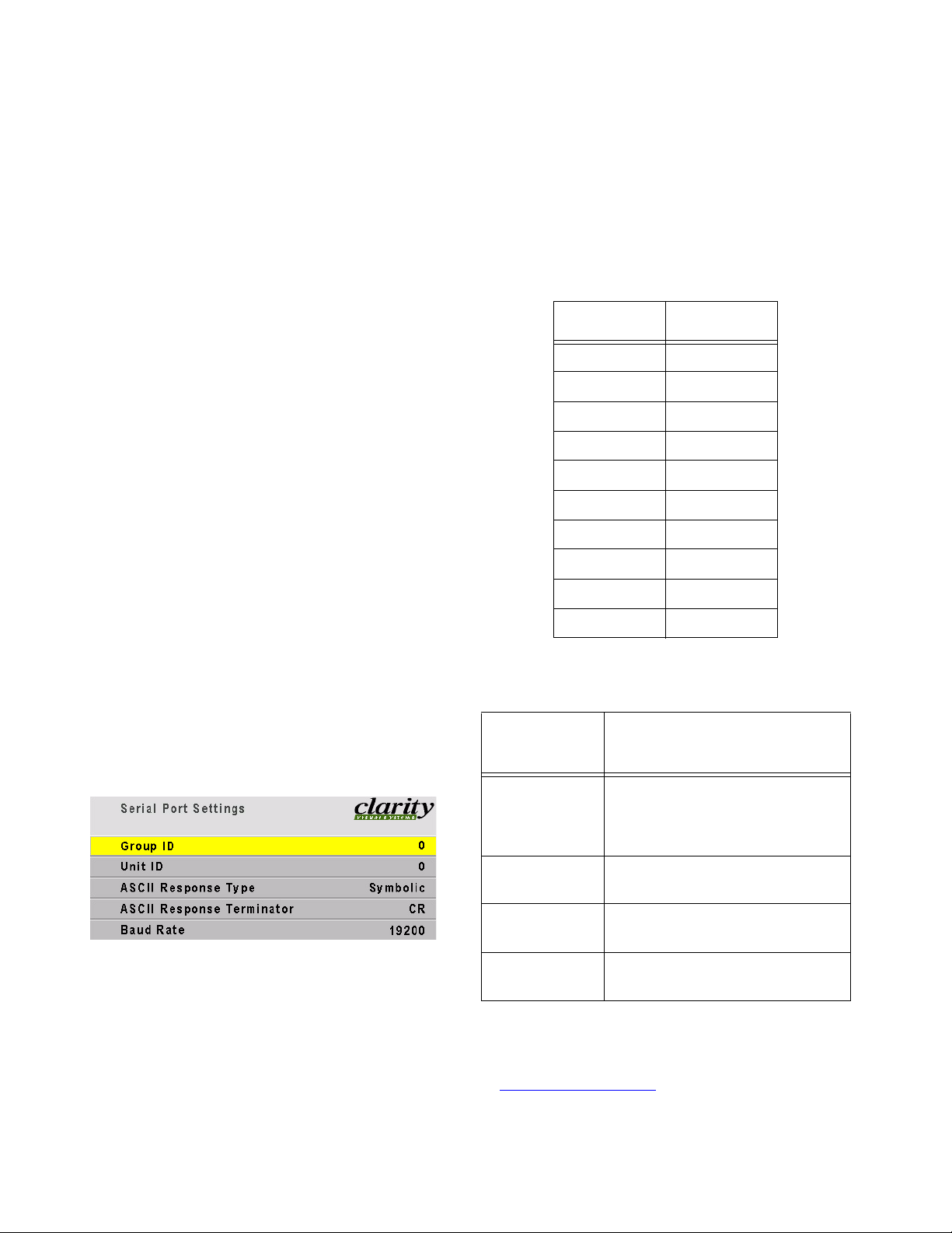
3.5.4 Serial Ports Settings
This applies only if you use RS232 commands to control the Bay Cat.
If you wish to control Bay Cats remotely with RS232
commands from a computer, read this section. Otherwise, skip it.
Bay Cats can be linked together for RS232 using
straight-thru 8-conductor cable with RJ-45 connectors. This is the common type of LAN connection
cable, not null-modem, sometimes call Cat-5 cable.
Adapter from computer to RJ45
At the computer end, you will need an adapter to
go from the computer’s 9-pin serial output connector
to a female RJ45 connector. Electronics stores have
these ready-to-wire types. Buy one with a female
9-pin sub and connect the wires as shown.
Wiring the adapter
To go from 9-pin D-sub serial connector on the back of
the ccomputer to an RJ45 connector, use a standard
RJ45-to-9-pin adapter. Wire it internally as shown. The
wiring shown for this adapter is correct for straight-thru
cables. Straight-thru cables are wired 1-to-1, 2-to-2,
etc.
Yellow w i r e p i n 3
Black wire pin 2
Green wire pin 5
RJ45 9-pin
63
55
Setting the ID
Each Bay Cat in the RS232 series needs a unique
ID so it can be individually addressed. The ID is in
two parts, Group ID and Unit ID. Each of these has a
range of 0–9, A–Z. This range results in 1296 possible addresses.
You can group the Bay Cats by using the same letter or number of the Group ID, such as 8. In this way
you can address the group as 8*, and all the Bay Cats
in the string that have Group ID 8 and any Unit ID
will execute the command. See the RS232 programming guide for Bay Cat (part number 070-0108-02 or
later) on www.ClarityVisual.com/login/
.
1. Click the lower, blue button.
2. Use the name “tech” and password “help”.
Response type and terminator
The ASCII Response Type determines what type
of data will be returned to the computer. For human
readable text in a serial program choose Symbolic. For
computer-read data you can use Numeric or Data
Only.
The ASCII Response Terminator will be deter-
mined by what you serial program wants to see at the
end of every transmission from the Bay Cat.
Baud Rate must be the same as that used by the
controlling computer. The baud rate is not automatically set, as it is with modem communications. It
must be manually set here and at the computer to
match each other.
32
1
23
4
5
6798
female 9-pin
Connect all the Bay Cats together through their
RS232 ports: from the computer to the first Bay Cat
RS232 IN; from the first Bay Cat RS232 OUT to the
next Bay Cat RS232 IN, etc. It doesn’t matter what
order you string them together. Most RS232 signals
easily travel up to 150 ft. (50 m) between Bay Cats.
58
Diagnostics for RS232
The Fans & Diagnostic Values menu has two
items that concern RS232:
• Last RS232 Packet T ype will usually be Operation
or Event, but it might be Error.
• RS232 Packets Received is a counter of the num-
ber of messages received by this Bay Cat, whether
they were addressed to it or not. It is not resettable. It counts up to 32767 and then wraps to 0.
Page 69

59
Page 70

3.6 Cleaning the Screen
The screen is covered with a protective acrylic sheet.
Clean the screen with a soft cloth or lint-free paper
towel and a mild cleaning solution. Ordinary window
cleaning products, such as Windex™, are safe.
CAUTION
Prevent liquid from running down the screen
and leaking into the interior of the Bay Cat.
Spray liquids on the cloth or towel, not directly
on the screen.
CAUTION
If you use a cloth towel, be sure it is clean. If
the towel was used to clean counter tops or
anything else, it may contain grit which could
scratch the acrylic screen protector.
60
Page 71

4 Reference Section
4.1 Menu Structures … 60
Picture … 60
Input Levels … 61
Video Adjustments … 62
Position … 63
Aspect Ratio … 64
Message In Picture … 65
Diagnostics: Test Patterns … 66
Diagnostics: Hours … 67
Diagnostics: Fans & Values … 68
Advanced Options: Menu Options, Auto Setup … 69
Advanced Options: Color Balance … 70
Advanced Options: Misc Options … 71
Advanced Options: Backlight Control … 72
Advanced Options: Force Analog Mode … 73
Advanced Options: Serial Port Settings … 74
Program Information: … 75
4.2 Remote Control Buttons … 76
4.3 Drawings … 78
4.4 Connector Locations and Diagrams … 82
4.5 Glossary of Terms … 84
4.6 Specifications for Bay Cat … 88
4.7 Regulatory Information … 90
4.8 Tables of Modes for Analog Inputs … 94
61
Page 72

4.1 Menu Structures
The gray text in menus is for information only. You cannot move the yellow selector to these lines.
Some menus change their appearance depending or the source selected or other factors.
Picture
Source chooses the source (the input
connector you want to use) and adjust
the picture. Use the +/– keys to select
the source. Digital pictures can’t be
adjusted.
Colorspace is either RGB or YPbPr
Frequency and Phase, see “Selecting
the Picture” on page 30.
Lock Settings unchecks all the boxes in
Auto Setup Options (see page 71).
FREQ/PHASE key
opens the Picture
menu directly.
The Comp Video Picture menu looks the same.
62
Page 73

Input Levels
To set levels semi-automatically, display a black pic-
ture from the source computer. Choose Auto Black
Level and press ENTER. Then display a white picture
from the source, choose Auto White Level and press
ENTER.
The Bobcat is now adjusted to the brightest and dark-
est picture this one source can produce. If you
change the computer to a different one, or change
the video card in the computer, you should do this
adjustment again.
LEVEL key opens the
Input Levels menu
directly, when the
source is Analog.
To set levels manually, display a black picture from the source computer.
Select Manual Black Level and adjust it until one of the three colors just
touches the 0 value. Then adjust the other two colors until they just touch 0
also. Do not push this value “lower” than 0, because the number will not
change, but the picture will get worse.
Now display a white picture from the source computer. Select the White lev-
els and adjust them until the value just touches 255. Do not push them
“higher” than 255, because the number will not change, but the picture will
get worse.
63
Page 74

Video Adjustments
Scaler Sharpness is similar to the Sharpness control for Analog
RGD sources.
Video Sharpness is a filter applied to the video picture before it
gets to the Scaler Sharpness filter.
Blue Only is used with source color bars for adjustment. It is
visible only when the source is Comp Video or S-Video.
LEVEL key opens the
Video Adjustments menu
directly, when the source
is composite or S-Video.
64
Page 75

Position
Image Pan moves the image on the screen.
SIZE/POS key
opens the Picture
menu directly.
65
Page 76

Aspect Ratio
The Bobcat’s aspect ratio is 16:9 or 1.77. This menu decides how to
handle source pictures that have other aspect ratios.
Fill Both Ways — Picture is stretched in one direction to make it fit.
This will cause some distortion, unless the source is 1.77.
Keep Aspect Ratio / Fill One Way — Picture is expanded until it
reaches the first border (sides or top-bottom). No distortion, but
extra space is filled with black.
Keep Aspect Ratio / Crop — Picture is expanded until it reaches the
second border (sides or top-bottom), and the rest of the picture
goes off the other edges (is cropped). No distortion, but some parts
of picture are lost from view.
1 to 1 / Keep Original Size — Picture is pixel-for-pixel as it is in the
source. No distortion, but extra space is filled with black.
66
WALL key opens
the Aspect Ratio
menu directly.
Page 77

Message In Picture
Recall Last MIP displays (turns on) whichever message last
appeared.
Timeout range is 0 to 60 seconds and is the length of time
before the message will disappear. 0 seconds means there is
no timeout, and the message will not automatically disappear.
Messages are stored in the Bay Cat only through RS232. See
the “MIP Guide” document 077-0004 found at:
www.ClarityVisual.com
Click on
Then click on lower, blue LOGIN NOW
User name: tech
Password: help
LOGIN
67
Page 78

Diagnostics:
Test Patterns
68
Move through Te s t P a t t e r n s
with the up-down arrow keys.
Page 79

Diagnostics:
Hours
System Time is the total time AC power has been applied.
Running Time is the total time the lamps have been on.
69
Page 80

Diagnostics:
Fans & Values
Fans OK means all the fans are running normally.
Last RS232 Packet Type is usually Operation, but could be
Key, Event, String or Error. This is the type of packet most
recently received by Bobcat.
RS232 Packets Received is the number of messages, not
bytes, received. This count goes up to 32767 and then
reverts to 0.
Rx Buffer Overflows and Errors keeps track of communica-
tion problems with received RS232 communications data.
Left and Right measure the light falling on the back of the
LCD from the backlights. When there is a wide imbalance, it
indicates that on of the backlights may have failed.
Amb is the measured value of the ambient light.
HPeriod is the time between on H pixel and the next, as
detected by the system.
VLines is the total number of vertical lines, active and hidden,
as detected by the system.
70
Page 81

Advanced Options:
Menu Options,
Auto Setup
H and V Position move the menu on the screen, not the picture.
Menu Timeout is in seconds. Menus disappear after this time
when there is no remote control activity. Zero seconds means
menus do not disappear.
Menu Rotation rotates the menu for Portrait orientation. It does
not rotate the picture.
(See also“Advanced Options”, page 50.)
MISC opens the
Advanced
Options menu
directly.
The checked events in Auto Setup Options occur when
• the input changes, say from XGA to UXGA
• a new source is selected
• you press the SETUP button.
Retry on lost signal, when checked, means the Bobcat
will look for a valid picture on the other connectors
whenever sync on the current connector is lost. Bobcat
will stop on the next connector that has a picture
(sync).
Do Quick Black/White Levels automatically adjusts the
lightest and darkest pixels to be white and black. This
fully automatic method is prone to small errors in the
white level. Semi-automatic level adjustment is better.
See Input Levels.
(See also“Advanced Options”, page 50.)
71
Page 82

Advanced Options:
Color Balance
Color Balance menu is used to adjust the color of the displays in a
wall so they all match. See “Adjusting Color Balance” on page 46
for complete details.
Color Temperature is used to pre-set the values to 3200K, 5500K,
6500K or 9500K. Each of these choices sets specific values in the
rest of the menu. When Color Temperature is set to Custom, use
the White Balance and Gray Balance adjustments to match adjacent displays. See “Adjusting Color Balance” on page 46.
Te s t P a t t e r n can select White, Gray or Off.
Reset to Defaults returns all white values to 31 and all gray values
to 7.
72
Page 83

Advanced Options:
Misc Options
Auto Backlight turns on the backlight soon
after AC power is restored.
Curtain Pattern is displayed when there is no
source.
Turn Backlight Off saves lamp life and energy.
Ignore RS232 CRC will make the Bobcat
accept c-type and byte-type commands,
regardless without CRC checking.
Enable Image Orbiting moves the image
slowly, reducing the possibility of temporary
image retention.
Clear Input Memory erases the memories that
save the input values for most recently used
10 sources. Use this if the Bay Cat won’t properly acquire a new source.
MISC opens the
Advanced
Options menu
directly.
(See also“Miscellaneous Options”, page 52.)
73
Page 84

Advanced Options:
Backlight Control
Ambient Light is the light currently in the immediate area of
the Bobcat.
Backlight Control Mode is either Auto or Manual.
Backlight Intensity can be controlled when Backlight Control
Mode is Manual. The range is 33 to 100%. In Auto mode,
Backlight Intensity is read only.
Ambient Threshold is the light intensity below which the back-
lights go to the Low Intensity setting.
Low Intensity is the backlight level (as a percent of maximum)
the light will go to when the ambient light falls below the
Ambient Threshold. There is a built-in 5 minute delay before
the low intensity takes effect.
(See also“Backlight Control and Status”, page 54.)
74
MISC opens the
Advanced
Options menu
directly.
Page 85

Advanced Options:
Force Analog Mode
Select Mode Number lets you choose the mode manually.
The Enable Force Mode must be unchecked to start.
Find the appropriate mode from the table on page 94, and
dial it into the Select Mode menu. As the mode number
changes, its settings are displayed in the line below.
When the desired mode is selected, check Enable Force
Mode.
Current Mode shows the mode number that the Bay Cat is
using now. This number will match the Select Mode number right after Enable Force Mode is checked.
You can find the value of the current mode my making Select
Mode number match the Current Mode number and reading the result in the resolution line.
MISC opens the
Advanced
Options menu
directly.
75
Page 86

Advanced Options:
Serial Port Settings
Group ID and Unit ID together make up at two-character ID for
this Bay Cat. In a group of Bay Cats connected in a series for
RS232 commands, each Bay Cat should have a unique ID.
ASCII Response Type is Symbolic (ascii words are returned),
Numeric (numbers are returned), or Data Only (only the data
value is returned.
ASCII Response Terminator is the non-printing character or
two-character combination that will end each response sent.
Baud Rate must match the baud rate of the host computer.
For complete information, see the RS232 Control manual for
Bay Cat available
lower, blue button. Use name “tech” and password “help”.
76
on www.ClarityVisual.com/login/. Click
MISC opens the
Advanced
Options menu
directly.
Page 87

Program Information:
When Clarity provides upgraded firmware
(software used in the Bay Cat), it will be
available at www.ClarityVisual.com.
Click on LOGIN
Then click on lower, blue LOGIN NOW
User name: tech
Password: help
77
Page 88

4.2 Remote Control Buttons
Starts searching for the next
available source
The setup button starts all the auto
setup processes that are marked ×
in the Auto Options menu.
78
Second press of
MISC button
Page 89

…when source is composite or S-Video
Turns curtain on and off. When curtain is on, source picture is blocked.
Turns backlight (lamp) on
Turn s b ack l i ght o f f
Raise and lower values in menus
If the current menu does not have
value bars in it, these buttons select
the highlighted item.
…when source is Analog
This button has no function for
Bobcat.
Reverts to the previous menu
Goes to the selected menu, or
performs the selected function
Navigate through menus by highlighting items. Select by pressing
ENTER.
79
Page 90

4.3 Drawings
Dimensions in inches.
80
Page 91

Side view of Bay Cat, measure
to rear of installed bracket.
81
Page 92

828384
Page 93

Page 94

4.4 Connector Locations and Diagrams
n
I
n
g
I
o
l
o
a
e
n
A
/
l
a
t
i
g
i
C
o
m
n
d
I
i
V
o
e
p
d
i
v
-
S
A
C
t
u
n
I
O
2
R
S
2
3
3
2
2
S
R
D
n
I
6½"
7"
23½"
8"
11¼"
12½"
Page 95

Wiring for RS232 9-pin to RJ45 adapter
The wiring shown for this
adapter is correct for
straight-thru network
cables.
18
RJ45 looking into the
socket.
5
Yellow w i r e p i n 3
Black wire pin 2
Green wire pin 5
RJ45 9-pin
63
55
32
1
23
4
6798
85
Page 96

4.5 Glossary of Terms
Terms used in this manual, and general terms.
Te r m Meaning
aspect ratio The ratio of the width to the height of a
picture, often expressed as 4-by-3,
4:3, 4×3, or 1.33:1 (the aspect ratio
of standard television pictures). 16by-9 (1.77:1) is the aspect ratio for
high-definition TV.
Clarity Display Aspect Ratio
Lion X, UX, XP, UXP,
XL, UXL
Panther UX, UXP
Puma X, XP, UXP
Tigress S, X
Wildcat S, SE
Lion SX, SXP 1.25
Bobcat 1, 2 1.66
Bay Cat, Margay 1.77
Backlight The fluorescent lamp or lamps behind
a direct-view LCD panel that make its
pictures visible.
ballast The electronics part (module) that
powers the lamp, providing high volt-
age to start the lamp and a lower volt-
age for operation.
1.33
Te r m Meaning
cube One display without regard to others
that may be in a wall with it.
See also unit; display.
C-Video Composite video; a video distribution
system in which all the video information, is sent on one wire.
DA Distribution amplifier; a device that
takes in one input and gives out
many of the same type. DAs are available for video, computer and digital
signals.
display One display unit without regard to oth-
ers that may be in a wall with it.
DVI Digital Video Interface, a standard for
distributing computer pictures in digital form.
electronics
module
The electronic part that controls
almost everything about the display.
It converts incoming pictures to a
form the LCD can use to display pictures and provides control through
the remote control and RS232 connections to other functions, such as
turning lamps on and monitoring
fans.
Bay Cat The name for a Clarity direct-view LCD
display, similar to a Clarity Bobcat,
but with a larger screen (46”) and
higher resolution (1920x1080). Model
number SN-4610-1080
Bobcat The name for any Clarity model begin-
ning SN-4025 or SN-4035. A 40"
direct view LCD display of 1280 ×
768 pixels.
composite
sync
composite
video
86
Sync signals that combine the hori-
zontal and vertical syncs onto one
signal line, separate from the video.
RGBS uses this type.
A video distribution system in which all
the video information, is sent on one
wire. Sometimes called C-Video.
Fast key One of the buttons on the remote con-
trol that takes you directly to a menu
or chain of menus.
H & V sync Horizontal and vertical sync on two
separate lines. The VGA family uses
this type.
key a push button on the remote control
LCD Liquid Crystal Display: the imaging
device used in the Lion, Wildcat, and
Panther displays. It works something
like a digital watch, but in three colors
and with greater detail.
LED Light Emitting Diode: a small, low
power lamp used as an indicator,
often red or green, but can be other
colors.
Page 97

Te r m Meaning
Te r m Meaning
Lion The name for any Clarity model begin-
ning WN-6720.
Margay Model WN-5040-720, a DLP™ optical
engine with one lamp and a resolution of 1280 × 720
module A stand-alone electronic assembly.
Clarity displays are designed to be
serviced at the module level, not the
component level. That is, the technician changes the whole electronics
module rather than changing a small
part in it.
mullion The metal edge surrounding the
screen material that holds the screen
in place.
native resolu-
tion
NTSC The television system used in North
PAL The television system used in most of
Panther The name for any Clarity model begin-
power supply The device that converts the mains AC
Puma The name for any Clarity model begin-
remote The remote control.
RGB Red, green, blue; three parts of a
RGBHV RGB plus sync, where H and V sync
RGBS RGB plus sync, where composite sync
The resolution of the LCD or DMD
itself. This is the highest resolution
the display can show, but in some
products the display will accept
higher resolutions an
America, Japan and parts of South
America. It stands for National Television Systems Committee, the group
that originally approved it. See also
PAL a nd SECA M .
the world. It stands for Phase Alternation Line. See also NTSC and
SECAM.
ning WN-6740 or WN-6730.
voltage to other voltages that the rest
of the display can use.
ning with WN-5020 or WN-5010.
video signal sent on separate wires.
See also YPbPr.
are on separate wires.
is on a separate wire.
SECAM The television system used primarily
in France, Russia and the former
Soviet Bloc countries. Sequential
Color and Memory. See also NTSC
and PAL.
SOG Sync on green, usually for RGB
sources
source A source of pictures, such as a com-
puter, a VCR, a DVD player or the
loop-thru from another Clarity cube.
SVGA S
S-Video A video distribution system in which
SXGA S
sync on green The sync part of the signal is com-
Tigress The name for any Clarity model begin-
unit One complete display. See also cube;
UXGA U
VGA V
video In this manual, video means NTSC,
video input
module
uper VGA, a standard for distributing
analog computer pictures with a resolution of 800 pixels by 600 pixels.
the luminance (brightness) and
chrominance (color) are sent on separate wires. Short for Super Video.
uper extended VGA, a standard for
distributing analog computer pictures
with a resolution of 1280 pixels by
1024 pixels.
bined with the green channel in RGB
video. Also called SOG.
ning with WN-5230. The original
Tigress, no longer produced, has
been replaced by the Tigress S and
Tigress X, whose model numbers
start with WN-5230A.
display.
ltra-extended VGA, a standard for
distributing analog computer pictures
with a resolution of 1600 pixels by
1200 pixels.
ideo Graphics Adapter, a standard
for distributing analog computer pictures with a resolution of 640 pixels
by 480 pixels.
PAL or SECAM pictures.
See VIM
87
Page 98

Te r m Meaning
VIM Video Input Module: an optional board
which plugs into the electronics module that allows S-Video and composite video inputs.
wall A group of displays physically bolted
together. (Not possible with Panthers.)
Wildcat The name for any Clarity model begin-
ning WN-4030.
WXGA W
XGA eX
Y One of the components of “compo-
YPbPr Designators for the three conductors
ide XGA, a standard for distributing
analog computer pictures with a resolution of 1280 pixels by 768 pixels.
tended VGA, a standard for distributing analog computer pictures with
a resolution of 1024 pixels by 768 pixels.
nent” video. See also component
video and colorspace.
in component video.
Y = luminace signal
Pb = B-Y (blue – luminance) signal
Pr = R-Y (red – luminance) signal
88
Page 99

89
Page 100

4.6 Specifications for Bay Cat
Mechanical
Specification Maximum Minimum Typical Notes
Outside dimensions
Width 44.0" 1117.6 mm
Height 26.1" 662.9 mm
Depth 3.9" 99.1 mm
Weight 71.2 lbs. 32 kg
Shipping weight 100 lbs 45.4 kg
Orientation Landscape or portrait
Chassis color Standard: dark gray
Optional: red, blue, silver, white, beige
or custom color
Ventilation requirement (rear) 0" Wall mountable
Screen dimensions Aspect ratio 1.77 (16:9)
Diagonal 46.0" 1168.4 mm
Width 40.1" 1018.5 mm
Height 22.6" 574 mm
Pixel pitch 0.53025 × 0.53025 mm
Electrical and Heat
Specification Maximum Minimum Typical Notes
Video input amplitude
Separate RGB analog 1.0 V p-p 0.5 V p-p 0.7 V p-p 75 ohm termination
Composite analog 5.0 V p-p 0.3 V p-p 75 ohm termination
TTL H and V sync 5.0 V 2.5 V 3.5 V TTL at 330 ohm termination
Input connectors
DVI-I Digital or Analog
15-pin HD D-sub DVI-I to 15-pin adaptor included.
RCA Composite video: NTSC, PAL, SECAM
Mini nDIN 4-pin S-Video: NTSC, PAL
RJ45 RS232 In
AC requirements
Line voltage 115 V range
230 V range
Power 240 W
Current 115 V 3.0 A
230 V 1.5 A
Heat, BTUs per hour 820
120 V
240 V
100 V
200 V
50-60 Hz auto-ranging, power factor
corrected
90
 Loading...