

Page 1
Cll
C
arriitt
a
y
y
U
U
s
s
err
e
G
G
uii
u
d
d
e
e
March 1, 2011 Part 87392-11, Rev. 1.06
Page 2

Warnings, Cautions and Notes as used in this Guide
WARNING
This publication uses Warning notices to emphasize situations in which
hazardous voltages, temperatures, or other conditions associated with the use of
this equipment could cause personal injury or serious damage to the equipment.
In situations where inattention or misuse could cause either personal
injury or serious damage to the equipment, a Warning notice is used.
CAUTION
operating instructions are not followed.
Caution notices are used where equipment might be damaged if proper
NOTE
Notes call attention to information that is especially significant for proper
understanding and operation of this equipment.
This document is based on information available at the time of its publication. While efforts have been
made to be accurate, the information contained herein does not purport to cover all details of the
hardware or software, or to provide for every possible contingency in connection with installation,
operation or maintenance.
Safety Reminders
• DO NOT operate this equipment until you have read and understood this manual. If operating
for the first time, ask your supervisor or a qualified operator for assistance.
Plug the power supply into a grounded receptacle ONLY. Do not cut off the grounding prong
•
or use any power cord or adapter without a grounding prong.
Always assume the power is ON. Do not attempt any maintenance until you have verified that
•
the power is OFF by unplugging the power supply from the Clarity.
Never turn the machine on while someone is performing maintenance or repair.
•
Keep your hair, hands, and clothing clear of the machine while it is in operation.
•
This product is not intended to be used in an explosive environment.
•
•
Unit should be positioned so that it can easily be disconnected from the power source.
THINK SAFETY FIRST – ALWAYS PRACTICE SAFE WORK HABITS.
Clarity User Guide, March 1, 2011 - Rev. 1.06
Page 2
Page 3

TABLE OF CONTENTS
Page
Chapter 1 - Getting Started............................................................................................................. 5
Unpacking the Clarity ........................................................................................................... 5
Foam Shipping Blocks in the Blocking Chamber................................................................. 6
Block #1 - #33593 - Bottom Shipping Block........................................................... 6
Block #2 - #33592 - Rear Shipping Block............................................................... 7
Shipping Bracket Used in the Blocking Chamber................................................................. 7
Shipping Bracket Assembly, #33648....................................................................... 7
Installed Shipping Bracket Assembly ...................................................................... 8
Clarity Front View - User Items............................................................................................ 9
Clarity Rear Connector Bulkhead .........................................................................................10
Accessory Kit........................................................................................................................10
Installing the Glass Plate.......................................................................................................11
Installing Light Shielding......................................................................................................11
Chapter 2 - Basic Operation............................................................................................................13
Powering on the Clarity.........................................................................................................13
Establishing Communications...............................................................................................13
The Touch Screen Display and Job Screen...........................................................................14
The Processing Screen ..........................................................................................................15
The Analysis Screen..............................................................................................................16
The Teach Function...............................................................................................................17
The Teach Screen.....................................................................................................18
Chapter 3 - Setup Screens................................................................................................................21
Main Menu Screen................................................................................................................21
Preferences Screen ................................................................................................................22
Key Features of the Preferences Screen................................................................................22
Batch Blocking.........................................................................................................22
Auto Blocking Mode................................................................................................22
Add Verification.......................................................................................................22
User Interface...........................................................................................................22
Tolerances Screen .................................................................................................................23
Interface Screen.....................................................................................................................24
Key Features of the Interface Screen ....................................................................................24
Display of Communication Events on the Main Menu............................................24
Hide Patient Name Received From Host for Privacy...............................................24
Run 30-Second Loopback Test................................................................................24
Communications Log...............................................................................................24
Blocking Screen ....................................................................................................................25
Key Features of the Blocking Screen.......................................................................25
Standard Finish Block Size, Small Finish Block Size (Half Eye),
Extra Small Block Size ...............................................................................25
PD, Seg Height, Axis ...............................................................................................25
Block Size Safety Margin ........................................................................................25
Blocker Arm Load Position......................................................................................26
Calibration Screen.................................................................................................................26
Advanced Screen...................................................................................................................27
Clarity User Guide, March 1, 2011 - Rev. 1.06
Page 3
Page 4

Key Features of the Advanced Screen ..................................................................................27
Home........................................................................................................................27
Burn In .....................................................................................................................27
Distance, Near and Prism Power Checks.................................................................27
Technician Screen .................................................................................................................28
Statistics Screen.....................................................................................................................29
Chapter 4 - Calibration....................................................................................................................31
Calibration Screen.................................................................................................................31
Step 1: Preliminary Camera Focus.......................................................................................31
Step 2: Camera.....................................................................................................................31
Step 3: Screen Calibration....................................................................................................31
Step 4: Block Position Offsets..............................................................................................32
Step 5: Power Calibration ....................................................................................................32
Touch Screen Calibration......................................................................................................34
Chapter 5 - The Advanced Screen in the Setup Menu..................................................................37
Distance Power......................................................................................................................37
Near Power............................................................................................................................38
Prism Power ..........................................................................................................................38
Lens Feature Detection..........................................................................................................38
Auto-Run at Windows Startup..............................................................................................38
Warm-Up Time.....................................................................................................................38
Image ..................................................................................................................................38
Display Options.....................................................................................................................38
Setup Password ..................................................................................................................... 39
Job Data Log .........................................................................................................................39
Burn In 39
Home ..................................................................................................................................39
Chapter 6 - Maintenance.................................................................................................................41
Cleaning the Glass Plate........................................................................................................41
Cleaning the LCD.................................................................................................................. 41
Cleaning the Touch Screen ...................................................................................................41
Replacement of the Main Fuse Located on the Rear Bulkhead ............................................41
Maintenance Tips..................................................................................................................41
Intended Use & Limitations ............................................................................................................43
Glossary of Terms ............................................................................................................................45
Appendix A .....................................................................................................................................47
General Specifications...........................................................................................................47
Technical Specifications .......................................................................................................48
Appendix B - Certifications & Standards......................................................................................49
FCC Class A Device Compliance .........................................................................................49
Appendix C - Electrical Diagram...................................................................................................51
Appendix D - Certificate of Compliance........................................................................................53
Declaration of Conformity ....................................................................................................53
Clarity User Guide, March 1, 2011 - Rev. 1.06
Page 4
Page 5

Chapter 1 – Getting Started
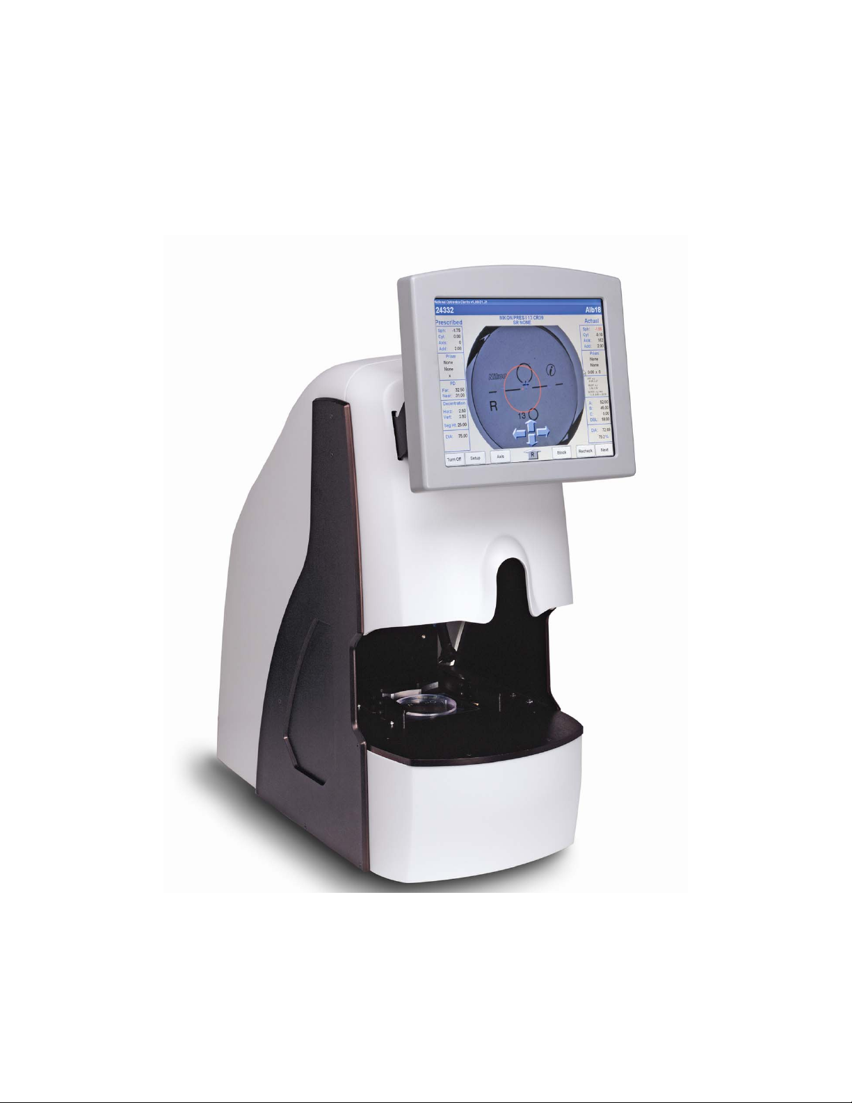
The Clarity Automated Lens Analyzer/Blocker is designed to verify all prescription
parameters including sphere power, cylinder power, axis, optical center location, prism, and
all add powers as well as thickness and front curve information. It will also affix a finish
block to the lens on axis at the geometric center of the frame shape. It is shipped in an almost
ready-to-run condition. This guide will allow you to put the Clarity into service quickly. We
will cover the following topics:
• Unpacking the Clarity
• Applying power and turning on the unit
• Connecting the unit to your lab’s computer system
• Using the touch-panel display and examining some of the operator screens
• Operation including lens insertion and blocking
• Calibration
• Advanced screen functions
The Clarity has many features and settings to allow you to optimize it for your specific lab
environment. It also has diagnostic capabilities and adjustments to fine tune its operation.
This guide does not describe all of the features or adjustments. Once you have become
familiar with operation as described in this guide and want more information, call Technical
Support.
Unpacking the Clarity
The Clarity is shipped in molded foam blocks within a cardboard carton. These blocks need to
be removed prior to removing the machine from the carton. An accessory kit is shipped in
two small cardboard inserts. The shipping carton and shipping materials should be retained in
the event that the unit must be shipped again.
Before removing the Clarity from the packing box and setting it up, please read this guide and
familiarize yourself with the accessories, features and terms used throughout the guide. There
is a glossary of terms in the back of this guide. Once the carton is opened, remove the two
inserts containing the power supply, power cord, and accessory kit. Remove the two side
panels and lift the unit out of the carton. Be careful to use the appropriate lift points. (See
Fig. 1.2) Place the unit in the desired location, but out of direct sunlight.
Inspect the contents to ensure you have all the items listed below. (See Fig. 1.4). There
should be 14 items in the two inserts. They are:
1. Power supply
2. Power cord
3. 70mm Plano CR39
4. 70mm -6.00 CR39
5. 65mm +6.00 CR39
6. 58mm calibration disc
7. White marking pen for progressives
8. Oval calibration template with permanent block attached
Clarity User Guide, March 1, 2011 - Rev. 1.06
Page 5
Page 6
9. Main fuse (located on rear bulkhead)
10. Glass plate (See Fig. 1.5) Remove and install in the blocking chamber as described
later in this chapter.
11. Light shield (blocking arm)
12. Light shield (left gripper)
13. Light shield (right gripper)
14. Bag of screws for the light shielding
15. Clarity User Guide (not shown in Fig. 1.4)
When the Clarity is prepared for shipment (by the factory or the user), its mechanism must be
secured against movement caused by jarring or shocks to the shipping carton. Units may use
one of two means for doing this: (1) molded foam blocks within the blocking chamber, or (2)
a clamping device attached to the blocking mechanism. In either case, the shipping restraints
must be removed prior to using the Clarity, and must be re-installed prior to shipping the unit,
should that prove necessary.
CAUTION
Shipping the unit without properly re-installing the factory shipping
restraints may cause severe damage to the equipment.
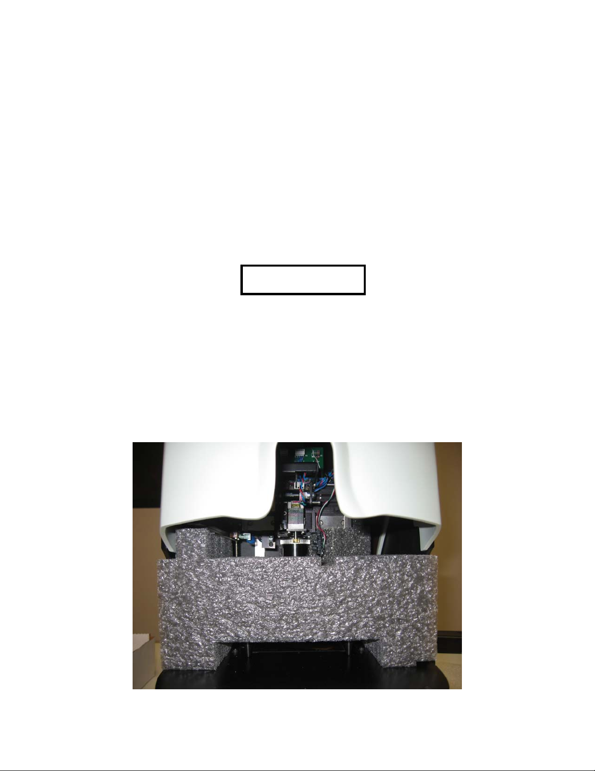
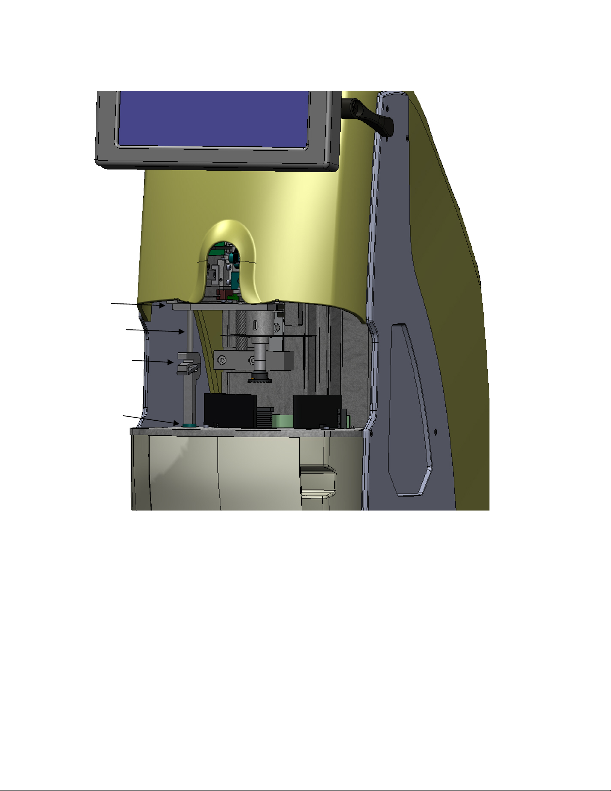
Foam Shipping Blocks in the Blocking Chamber
Remove the two foam blocks that hold the mechanism in place during shipment. Note how
they are installed in the event that the Clarity needs to be shipped from your location. Call
Technical Support for help in packing the machine for shipment. Figures 1.1a and 1.1b show
how the foam shipping blocks are installed.
Figure 1.1a - Block #1 (P/N 33593 - Bottom Shipping Block)
Clarity User Guide, March 1, 2011 - Rev. 1.06
Page 6
Page 7
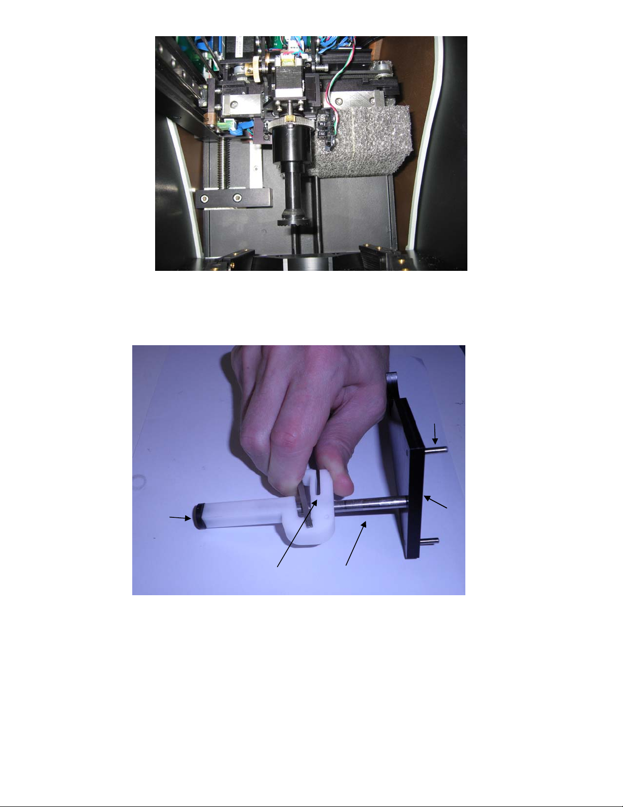
Figure 1.1b – Block #2 (P/N 33592 - Rear Shipping Block)
Shipping Bracket Used in the Blocking Chamber:
Foot
Foot
Locating
Locating
Plate
Plate
Pinch Lock
Pinch Rod
Figure 1.1c – Shipping Bracket Assembly, Clarity (P/N 33648 )
The Shipping Bracket assembly is shown in Figure 1.1c. The Foot is placed on the base of
the blocking chamber. By squeezing the Pinch Lock, the Pinch Rod may be moved up or
down so that the cutout in the Plate engages the chuck and the Locating Pins engage the
bottom of the blocking mechanism. When installing the assembly, the Pinch Lock mechanism
should be moved downward so that the rubber Foot is slightly compressed. Figure 1.1d shows
the shipping bracket in its installed aspect.
Clarity User Guide, March 1, 2011 - Rev. 1.06
Page 7
Page 8
Plate
Pinch Rod
Pinch Lock
Foot
Figure 1.1d – Installed Shipping Bracket Assembly
Clarity User Guide, March 1, 2011 - Rev. 1.06
Page 8
Page 9
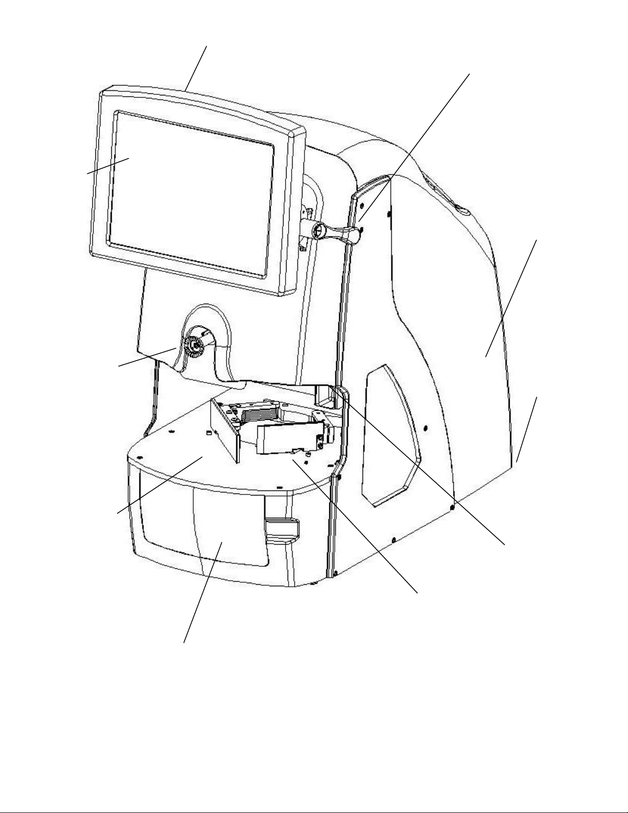
Touch
Screen
Display
Display Frame
Display Tilt Handle
Rear
Cover
Block Arm
(Extended or
Retracted)
Lens
Table
Drawer
Figure 1.2 – Clarity Front View - User Items
Gripper Arm
Lift Point
Lift Point
Clarity User Guide, March 1, 2011 - Rev. 1.06
Page 9
Page 10
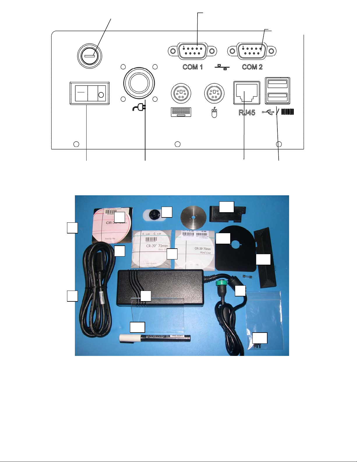
Fuse 5A, 250V
,
r
r
5x20mm
T5.0
Serial Port COM1
Serial Port COM2
Power
Switch
Power Supply
Connecto
Ethernet
Connector
USB
Connecto
Figure 1.3 - Clarity Rear Connector Bulkhead
8
5
4
6
3
13
11
12
2
1
9
10
14
Figure 1.4 – Accessory Kit
1. Power supply 8. Oval calibration template with permanent block attached
2. Power cord 9. Fuse (in the bag of screws)
3. 70mm Plano CR39 10. Glass plate
4. 70mm -6.00 CR39 11. Light shield (Blocking Arm)
5. 65mm +6.00 CR39 12. Light shield (Left Gripper)
6. 58mm calibration disc 13. Light shield (Right Gripper)
7. White marking pen
14. Bag of screws for the light shielding
s
Clarity User Guide, March 1, 2011 - Rev. 1.06
Page 10
Page 11
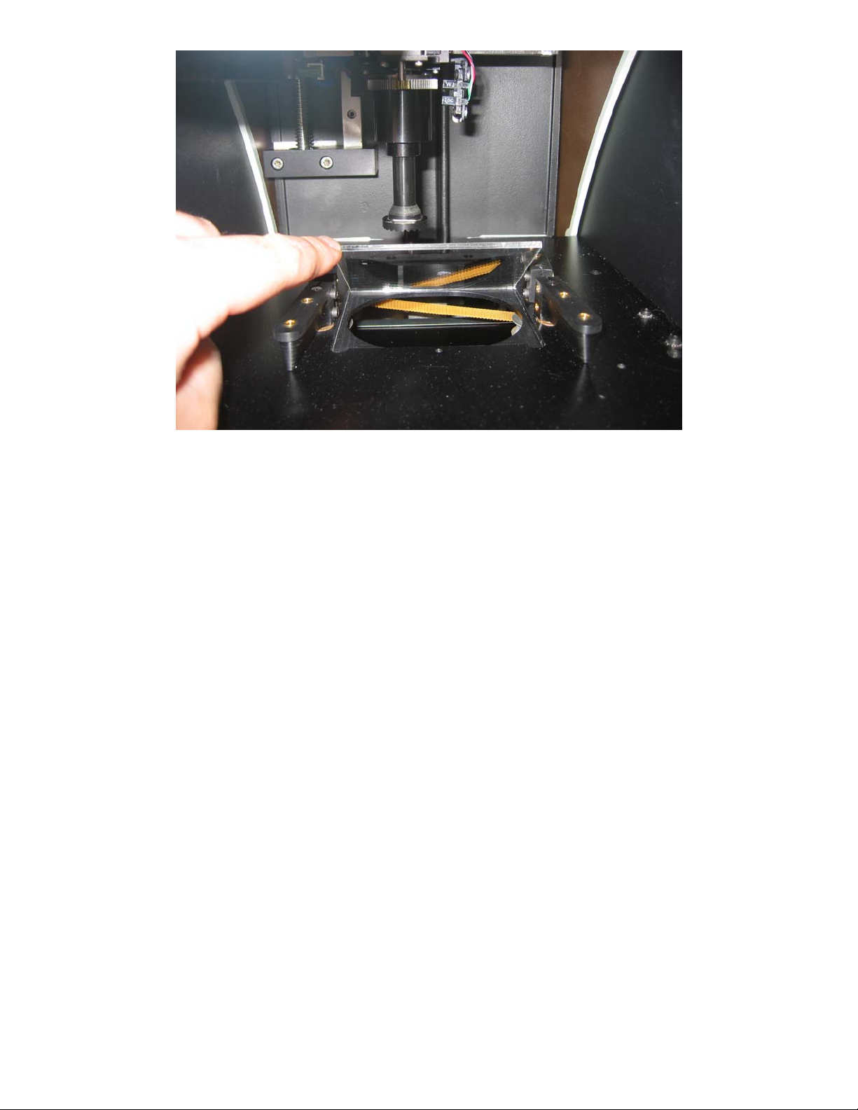
Figure 1.5 – Installing the Glass Plate
Installing the Glass Plate – The glass plate is placed over the opening in the base plate of the
blocking chamber. Clean the glass plate and then slide it into the pocket. It should fit and
seat down in the pocket fully. (The glass plate is shipped in the accessory box.)
Installing Light Shielding – This shielding is designed to reduce or eliminate light coming in
to the blocking chamber causing inconsistent lens analysis. The shields are not necessary in
all lab environments. Only if you see white or clear areas on the lens image (on screen)
during processing should the shields be needed. They are in the accessory box in the event
that there is too much light entering the chamber. There are three separate parts to the light
shielding including the left gripper shield, the right gripper shield and the blocking arm shield.
The left and right gripper shields can be installed using the screws in the accessory box to
secure them to the tops of the front gripper arms. There are two threaded holes for the screws
to attach the shields to the tops of each gripper arm.
The blocking arm shield requires that you remove the center screw of the blocking arm,
thereby removing the chuck. Place the shield over the arm with the flat side facing down.
Replace the chuck (align small hole on the back of the chuck with the locator pin) and insert
and tighten the center screw.
Clarity User Guide, March 1, 2011 - Rev. 1.06
Page 11
Page 12

(This page intentionally left blank for duplexing purposes.)
Clarity User Guide, March 1, 2011 - Rev. 1.06
Page 12
Page 13

Chapter 2 – Basic Operation
WARNING
Use only a grounded outlet. Do not defeat the grounding by cutting off the
grounding prong on the power cord, or by using a non-grounding adapter.
NOTE
The power supply module is designed to work with both 115 VAC (60 Hz) and with
230 VAC (50 Hz). A separate power cord is available for each application. In the
U.S., units will be shipped with 115 VAC power cord unless otherwise specified.
WARNING
The back case top should not be removed while the machine is powered ON. Power
the machine OFF and unplug from the wall.
Powering on the Clarity
• Make sure that the Clarity main power switch is in the OFF position. The side of the
switch with the symbol 0 should be depressed.
• Plug one end of the AC power cord into the power supply module. (Fig. 1.3)
• Plug the other end of the AC power supply cord into a grounded outlet.
• Plug the power supply module into the power socket on the rear connector bulkhead
shown in Fig. 1.3.
• At this time you can connect a serial cable for communications from the host computer to
COM 1 or COM 2, 9-pin serial port on the rear bulkhead. This method will require the
use of a null modem at either end of the serial cable.
• Once the unit is properly plugged in, both at the machine and the wall, press the left side
of the power switch (with the symbol l) to apply power to the Clarity. Within 6 to10
seconds, the display should become active and the mechanism should move to locate its
home position.
• Either of the two 9-pin serial ports on the rear bulkhead labeled COM 1 and COM 2 (may
show up in the Interface tab as COM 5 and COM 6 respectively) can be used to set up
serial communications.
Establishing Communications
At this time, you will want to set the communications to your lab software. From the Job
Screen, press EXIT, then select Setup, and then select the Interface tab. Choose the VC
Connection Method, and then set the Baud Rate and COM Port if you are using a serial
Clarity User Guide, March 1, 2011 - Rev. 1.06
Page 13
Page 14
connection. If you are using an Ethernet connection, then you must set the two ports in the
TCP/IP Network Auto-Connect Settings box.
CAUTION
Keep hands away from unit during the blocking function.
The Touch Screen Display and Job Screen
CAUTION
Do not use a sharp object (pencil or pen point, paper clip, etc.) on the touch screen as it may
scratch or tear the screen. Clean the screen with a microfiber cloth such as is used to clean
eyeglasses. A soft cloth slightly dampened with clear water may be used for hard-to-remove
spots. Turn the Clarity off before cleaning the screen.
The Clarity is equipped with a touch screen display. A mouse and keyboard can be installed
on the rear bulkhead if desired. A mouse is recommended to have at all times for manual
alignment of progressives, bifocals and trifocals. There are two USB ports that can be used as
well as two PS-2 connectors at the rear of the machine. (See Fig. 1.3) If you install a PS-2
mouse or keyboard while the machine is ON, you will have to reboot the machine (cycle the
power OFF and then ON) for the machine to recognize
there is a device connected.
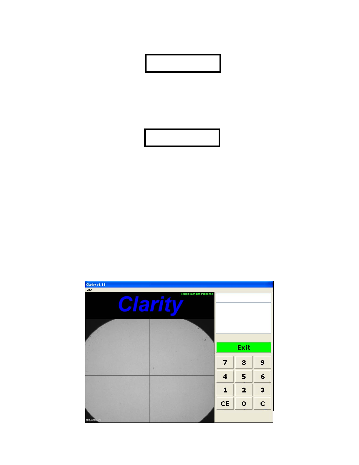
Once the unit is powered ON, it will boot to the main Job screen. (See Fig. 2.1.) The
program will open, initialize communications, and the camera will go through several checks.
Fig. 2.1 - Job Screen
Clarity User Guide, March 1, 2011 - Rev. 1.06
Page 14
Page 15
When a Job Number has been entered, the EXIT label on the control button changes to
PROCESS. Jobs are processed in one of the following three ways:
1. You may enter the job number manually with the touch screen keypad or keyboard
and then select PROCESS.
2. You may use USB barcode reader and scan a job number into the machine and then
select PROCESS.
3. You may enter multiple job numbers either manually or with the barcode reader by
going to the Preferences tab in the Setup menu and checking the box labeled Enable
Batch Blocking and activating Last in First Out, or First in First Out.
NOTE
Selection 3 above allows the operator to enter a large group of jobs (like a stack of trays) for
efficiency. The Clarity will then bring up each job in the order that was specified in the setup.
(See batch blocking in the glossary.)
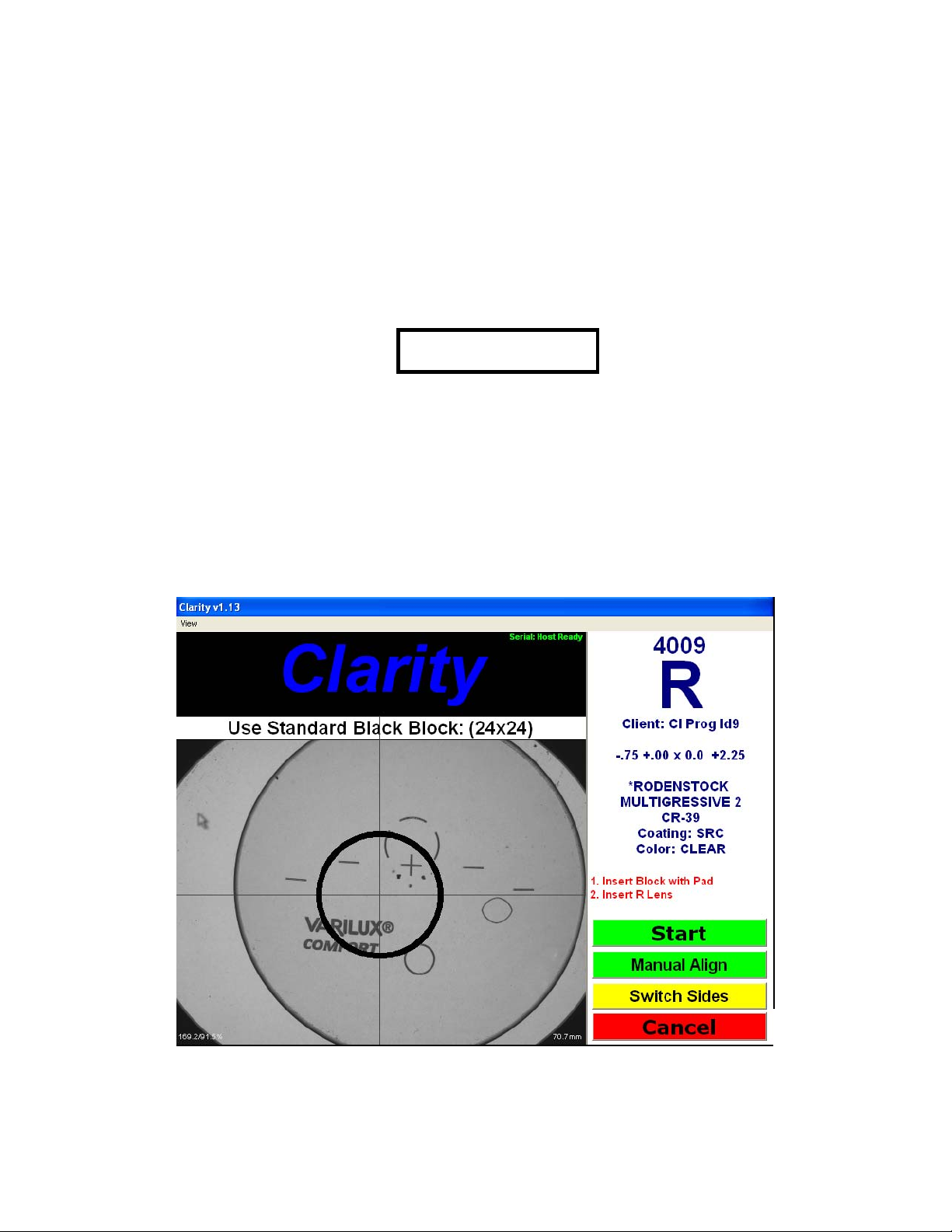
The Processing Screen
From the Job Screen, press the PROCESS control button to gain access to the Processing
Screen (Figure 2.2).
Figure 2.2 - Processing Screen
When the screen is first displayed, only two control buttons are shown in the lower right:
Switch Sides – Change displayed eye to the opposite side. OD is displayed initially.
Cancel – Return to Job Screen.
Clarity User Guide, March 1, 2011 - Rev. 1.06
Page 15
Page 16
As instructed by the screen prompts, load a block and pad onto the blocking arm chuck and place the
lens to be blocked on the glass plate in the blocking chamber. The Clarity automatically detects that a
lens has been loaded and displays two additional control buttons at the lower right:
START – Initiate the lens analysis/verification and blocking process.
Manual Alignment – Perform the lens alignment manually prior to blocking.
Select START to identify features of the lens and perform lens analysis.
The Manual Alignment button can be used instead of the Start button when a progressive is
known not to align properly. You can choose Manual Alignment and not have to wait for
analysis to proceed.
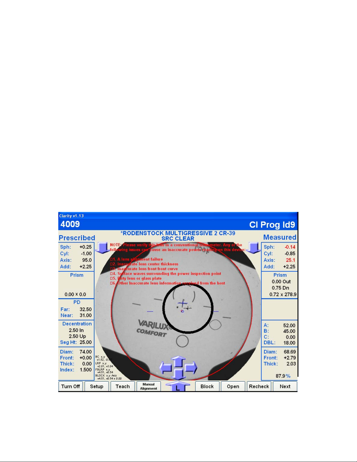
The Analysis Screen
The Analysis screen will appear and show the prescribed Rx information on the left side of
the screen and the measured information on the right side of the screen. Once the analysis is
complete, the measured information will be checked against the prescription to determine if
the lens meets ANSI standards. If the lens does not meet the tolerances, the individual
parameter(s) that are out of tolerance will be displayed in red. Those that fall within the
standards will display in black. (See Fig. 2.3.)
Figure 2.3 – Analysis Screen
Clarity User Guide, March 1, 2011 - Rev. 1.06
Page 16
Page 17

After the lens has been analyzed, the bottom of the screen will display eight buttons and five
arrows. (See Fig. 2.3.) The eight buttons are:
1. Turn Off – Exit the program and shut the power off.
2. Setup – Access the main Setup screen with tabs at the top of the screen for other setup
options.
3. Teach – “Teach” the Clarity how to analyze a problem lens. Described later in this
chapter.
4. Manual Alignment - Use this button whenever the camera misaligns a lens after
analysis. Proper alignment may be drawn on the screen using a mouse.
5. Block – Activate the blocking sequence. Typically this is the most used button after
the lens is analyzed. (See Figure 3.2 for automatic blocking.)
6. Open – Open the lens clamps to remove the lens from the chamber.
7. Recheck – Recheck the lens that is in the chamber.
8. Next – Exit the Analysis screen and return to the Process screen to enter a new job
number.
The arrows have two functions:
1. The lowest arrow that has either an R or an L in it allows you to switch to the other
eye for the job you are blocking on screen.
2. The four arrows (up, down, in, and out) allow you to change the block position in case
of cutout issues for the frame.
Once you have blocked the lens, the screen will prompt you to remove lens. The display will
then change to the left lens, or if this was the left lens, then it will return to the Process screen
to start the next job.
NOTE
If the information about the lens coming from the host program is inaccurate on any of
the following items, then the power measured could be inaccurate and out of tolerance.
1. Front Curve
2. Back Curve
3. Lens center thickness
4. Lens diameter
If you see power problems, check data coming from the host for that particular lens.
The Teach Function -- In some cases, the Clarity is unable to recognize the fitting cross on
progressive lenses. When this occurs, the user may use the teach function to “draw” the
fitting cross on the screen to “teach” the Clarity what it looks like. The teach function is
accessed from the Analysis screen via a button at the bottom of the screen. A mouse and
keyboard should be attached to the Clarity to effectively use the teach function. Upon pressing
the Teach button, a screen similar to that shown in Figure 2.4 will appear.
Clarity User Guide, March 1, 2011 - Rev. 1.06
Page 17
Page 18

Figure 2.4 – The Teach Screen
At the lower left of the screen, there may appear one or more images that the Clarity has
identified as candidates for the fitting cross. If one of these matches the actual fitting cross
and is on axis, left-click the image; it will move to the Image Box at the left top of the screen.
NOTE
Do not select a candidate image from the lower-left unless if is aligned. In Figure 2.4,
the image is not aligned so should not have been copied to the Image Box at upper left.
If there is no suitable candidate image at the lower-left, two alternatives re main for creating
an image:
1. Use the image cleanup tools and the mouse to draw an image in the image box. The
width of drawn pixels may be selected by clicking on one of the tool-width squares.
Select the black draw color to actually draw, and the white draw color to clear or
erase.
2. Click the Feature From Camera control. A screen shot of the lens will appear.
Rotate the lens if necessary to align it. Then use the mouse to draw a rectangle around
the fitting cross. The pixels enclosed in the rectangle will be copied to the Image Box.
The rectangle should be as small as possible but still include the complete image of the
fitting cross.
Once an image has been acquired (from among the candidates, or drawn, or copied from the
camera image) it may need to be “cleaned up” by removing stray pixels or adding pixels to fill
gaps. Use the Image Cleanup tools for this purpose. (Cleanup is especially important for
camera captures.) The result should be a clean image that nearly spans the width and height of
the Image Box.
Clarity User Guide, March 1, 2011 - Rev. 1.06
Page 18
Page 19

The image should be saved in the Clarity database. Images in the database are listed in the
upper-right of the Teach screen. Each image has a unique name that may be derived from the
lens type name, or entered via a keyboard. The first character of each name in the database
must be either a “+” or “ T ” to indicate whether the image is a cross or T-shape. T-shapes
may be upright or inverted. Once the name has been assigned, use the SAVE control to make
the database entry.
NOTE
The teach function cannot be used with fitting crosses that include gaps (white space).
Clarity User Guide, March 1, 2011 - Rev. 1.06
Page 19
Page 20

(This page intentionally left blank for duplexing purposes.)
Clarity User Guide, March 1, 2011 - Rev. 1.06
Page 20
Page 21

Chapter 3 – Setup Screens
Figure 3.1 – Main Menu Screen
The Setup screens are accessed by pressing the Setup button at the lower left of the Main
Menu screen. (See figure 3.1.) Specific setup functions are selected by using the tabs across
the top of the Setup screen. The tabs are:
Preferences
Tolerances
Interface
Blocking
Calibration
Advanced
Technician
Statistics
The screens associated with each tab are shown below. The meanings of most of the setup
options should be apparent to the operator. The descriptions provided in this chapter only
include highlights of features that may not be obvious. Complete guidance on using all of the
Setup screens may be obtained by phoning the Technical Support group.
Clarity User Guide, March 1, 2011 - Rev. 1.06
Page 21
Page 22

The Preferences Screen
Figure 3.2 - Preferences Screen
Key Features of the Preferences Screen
Batch Blocking: If enabled, the user may enter a series of job numbers. As each job
completes, the next job is automatically started. Use the check boxes to specify the order in
which the jobs are processed.
Auto Blocking Mode: In auto-blocking mode, the Clarity will block a lens that has been
successfully analyzed without operator intervention. Use the check boxes to select which
types of lenses may be auto blocked.
Add Verification: Many labs find it unnecessary to verify the add power once the distance
Rx has been verified. Leaving the boxes unchecked will reduce analysis time and improve
system throughput.
User Interface: Select either or both of these somewhat advanced features if desired. They
are most useful in processing “difficult” lenses in which the Clarity may not be able to find
alignment marks or the fitting cross.
Clarity User Guide, March 1, 2011 - Rev. 1.06
Page 22
Page 23

Tolerances Screen
Figure 3.3 – Tolerances Screen
The values on this screen indicate how closely a measured lens characteristic must match the
Rx in order for the verification to pass. The values are preset prior to shipment to ANSI
standards. You can customize the tolerances by selecting Custom and then changing any or
all of the parameters using the touch screen keypad. (If you switch to Custom and make any
changes to any or all of the tolerances, you can easily return to the ANSI standards by
selecting ANSI.)
Clarity User Guide, March 1, 2011 - Rev. 1.06
Page 23
Page 24

The Interface Screen
Figure 3.4 – Interface Screen
Key Features of the Interface Screen - This screen allows you to set the serial
communication baud rate for the port used. It also allows for the use of Ethernet, which
includes UDP and TCP/IP port setup.
Display of Communication Events on the Main Menu – Check this box to view
communication events on the Main Menu screen.
Hide Patient Name Received From Host for Privacy – If this box is checked, the patient’s
name will not be shown during processing.
Run 30 Second Loopback Test – Check this box to run a loopback test on the serial port.
This test verifies that the port can send and receive data. You must insert a loopback plug in
the port to perform this test. Press the test button. In the box below the button, you will see a
string of letters and numbers if the port is working. You will not see any characters in the box
if the port is not functioning.
Communications Log – This button is a diagnostic tool that may be used by Technical
Support.
Clarity User Guide, March 1, 2011 - Rev. 1.06
Page 24
Page 25

NOTE
Communication Events include packet requests, download a job, received packet,
timeouts, etc. If you place a checkmark in the box under Communications Display, you
will see communication errors on the screen. This can be a useful diagnostic tool.
The Blocking Screen
Figure 3.5 – Blocking Screen
Key Features of the Blocking Screen
Standard Finish Block Size, Small Finish Block Size (Half Eye), Extra Small Block Size
– Enter the dimensions for the finishing blocks used in your lab. Use the dropdown menu to
enter the color of each block.
PD, Seg Height, Axis – Enter values to correct any observed offset in these parameters across
all jobs.
Block Size Safety Margin – Specifies tolerance to ensure that the correct block size is used
under close tolerances between block B-size and frame B-size.
Clarity User Guide, March 1, 2011 - Rev. 1.06
Page 25
Page 26

Blocker Arm Load Position - Values are used to position the blocker arm so that it does not
collide with the slot in the case top.
The Calibration Screen
Figure 3.6 – Calibration Screen
This screen contains the calibration values obtained in performing the five calibrations
necessary for best performance of the Clarity:
Preliminary Camera Focus (described in the Technician Screen)
Camera Calibration
Screen Calibration
Block Position Offsets Calibration
Power and Prism Calibration
The preliminary camera focus calibration is performed via the Technician screen. The other
calibrations are described in Chapter 4: Calibration.
Clarity User Guide, March 1, 2011 - Rev. 1.06
Page 26
Page 27

The Advanced Screen
Figure 3.7 – Advanced Screen
This screen is discussed in detail in the last chapter of this guide. Please call Technical
Support before making any changes to this screen.
Key Features of the Advanced Screen
Home - To return all of the axes to their home position, press this button.
Burn In - Is used to exercise the axes, especially when the machine is cold.
Distance, Near and Prism Power Checks – Specifies both the number of power checks and
the number of power targets. Higher values improve accuracy but take longer. The Clarity is
set at the factory for the combination that provides optimum function balancing speed and
accuracy.
Other features:
• Update Software (Install new versions of software.)
• Set Date and Time
• Restore Data (If a backup was made, which is recommended.)
• Backup Data (Copy setup data to a USB thumb drive.)
• Import Lens Data (Used to import finished lens data for accurate power reading of stock
finished lenses.)
• Save Tech Data Save screen images of all the Setup screen tabs.
Clarity User Guide, March 1, 2011 - Rev. 1.06
Page 27
Page 28

There are two other buttons that will allow you to check and save job log data for analysis of
VC labels:
• View Log
• Copy Logs to Flash Drive
To copy or look at the log, you must have the Activate Job Log Data box checked. This
screen also includes a box to allow the machine to boot up completely past Windows and
open into the Clarity software. There is a Brightness Image Level that is set at the factory to
185. There is also a box called Display Options. These parameters should only be changed
with input from Technical Support. Advanced screen functions are discussed in detail in
Chapter 5.
The Technician Screen
Figure 3.8 – Technician Screen
When you select the Technician tab, a number keypad appears. Enter the password (082379)
to allow entry into the screen. This screen contains a wide variety of features that will be
useful in diagnostics. Contact Technical Support before making any changes to this screen.
This screen also contains a Focus Camera button that is used as a preliminary calibration of
the camera focus to optimize the camera's ability to recognize clearly the edge of the lens.
This, in turn, optimizes diameter checks and affects power readings.
Clarity User Guide, March 1, 2011 - Rev. 1.06
Page 28
Page 29

The Statistics Screen
Figure 3.9 - Statistics Screen
The box labeled Job Count shows the number of Single Vision, Bifocals, Trifocals and
Progressives that have been processed. There is a CLEAR button that will reset the counter
for all of the lens types.
The area labeled Stepper Motor Cycle Count has four boxes for the four motors the Clarity
uses. The X, Y and Z Axis Motors and the Block Axis Motor each have their own CLEAR
button so that you can keep track of the individual motor counts and clear the data when a
motor is replaced.
In the upper-left and center of the screen are a number of indicators related to LCD operation
and showing axis home switch status.
Clarity User Guide, March 1, 2011 - Rev. 1.06
Page 29
Page 30

(This page left blank intentionally for duplexing purposes.)
Clarity User Guide, March 1, 2011 - Rev. 1.06
Page 30
Page 31

Chapter 4 – Calibration
Figure 4.1 – Calibration Screen
A full calibration of the Clarity involves the following five steps:
Step 1: Preliminary Camera Focus: This step is performed from the Technician screen.
There you will find a button labeled Camera Focus. Select this button and follow the
instructions on the right side of the screen. This calibration will require the use of the 58mm
round pattern found in the accessory kit.
Step 2: Camera - This calibration sets the Brightness, Shutter and Gain of the camera.
Select the Calibrate button and a box will appear that is titled Remove Lens. Select OK and
in a couple of seconds another box will appear that will say The camera calibration is
completed. Select OK to complete this step.
Step 3: Screen Calibration – This calibration requires the use of the 58mm round pattern
found in the accessory kit. (See Fig. 1.4) Select the Calibrate button and a box will appear
titled Graphics Scale Calibration. It prompts you to put the 58mm round pattern in the
chamber and select OK. Within a couple of seconds another box will appear with the same
title saying that the screen graphics have been calibrated. Select OK to complete this step.
Clarity User Guide, March 1, 2011 - Rev. 1.06
Page 31
Page 32

Step 4: Block Position Offsets – The oval calibration template with a Vario block
permanently mounted and the 70mm plano CR39 lens are required for this calibration. This
process places the oval calibration template on the plano lens and takes a snapshot of the
position eight separate times to complete this operation. This will set the horizontal, vertical
and axis position. Select the Calibrate button and, after a few seconds, you will be
prompted to clean the glass plate and make sure no lens is in the chamber. (See Fig. 1.5.)
NOTE
Clean the glass plate using an A/R microfiber cleaning cloth. The glass plate is
removable and it may be necessary to clean the lower LCD under the glass plate. Refer
to the Maintenance chapter for details.
Select OK and the screen will change to the Block Position and Axis Calibration screen.
Select the Calibrate button and the first of eight boxes will appear. The box will direct you
through the operation.
1. Place the plano 70 mm lens (found in the accessory kit) in the blocking chamber.
2. Place a blocking pad on the alignment block. (See Fig. 4.2) The pad must have a hole
in the center to allow the camera to see through the hole on the center of the finishing
block.
3. Mount the alignment block on the blocking arm.
4. Select OK.
At this time, the machine will place the block on the lens and analyze the data to set the 0, 0
Coordinate Origin position (See Glossary) for X and Y and also set the axis. This calibration
will ask you to perform 1-4 above eight separate times. The software rotates the block 45
degrees each cycle.
Follow the on-screen direction until the calibration is complete. At the end of this calibration
three numbers will appear in the box for:
1. Horizontal offset (X)
2. Vertical offset (Y)
3. Axis (A)
NOTE
Look closely as the block is being placed on the lens. If you believe each of the eight steps were
completed with no block slippage or any irregular motion, then select OK to accept the new
offsets and continue to the power calibration. If you feel that any of the eight steps were
compromised, select Cancel and start the process over.
Step 5: Power Calibration – This calibration requires the use of the 70mm CR39 -6.00 and
the 65mm CR39 +6.00 lenses found in the accessory kit. This process will set the power
throughout the range of powers this device is able to verify.
Clarity User Guide, March 1, 2011 - Rev. 1.06
Page 32
Page 33

On the Calibration screen under Step 4 (See Fig. 4.1), there are six parameters that describe
the lens that will be analyzed:
1. Diameter
2. Index of Refraction
3. Power
4. Front Curve
5. Back Curve
6. Center Thickness
These parameters are for both the plus and the minus lenses.
NOTE
If these lenses are misplaced or compromised in any way, please call the factory and
order a new calibration lens. Once the new lens arrives, check these parameters and
make any necessary changes.
To perform this calibration, select the Calibrate button. You will be prompted to remove the
lens. Make sure there is no lens in the chamber and select OK. After 25 seconds, you will be
prompted to insert the calibration lens. Put the -6.00 lens in the chamber and select OK. The
Clarity will analyze the lens and will instruct you to place the +6.00 lens in the chamber.
Select OK.
After both lenses are analyzed, the plus and minus slope adjustments will be displayed. Select
YES to accept these changes. The calibration wizard will appear telling you that the power
calibration is complete. Select OK. To exit back to the Job screen, select OK at the bottom
of the screen and then on the next screen select Next.
NOTE
On this screen, there is also a Power Offset box. This can be used if you see a consistent
power error. For example, powers are showing 0.25 weak across the board. Enter a
+.25 and all analyzed powers will have 0.25 added to the final reading. This functions
like the manual eyepiece adjustment for power on a conventional lensometer.
This screen includes two parameters labeled Minus Prism Bias and Plus Prism Bias.
They are constants and should not be changed unless directed by the factory.
To verify power calibration, there is an internal job (Job Number 999999999) which will
allow you to use the two calibration lenses (+6 and -6). From the main Job screen enter the
Job Number 999999999 and follow the directions. Each lens will show the measured power
in the upper right hand corner of the screen. If they are within acceptable limits, you can
move on. If they are out of tolerance, recalibrate.
Clarity User Guide, March 1, 2011 - Rev. 1.06
Page 33
Page 34

Touch Screen Calibration
Fig 4.2 Touch Screen Calibration Screen
Touch Screen Calibration – In the upper right corner of the calibration screen there is a box
titled Touch Screen Calibration.
NOTE
This calibration is done at the factory and does not need to be done on a regular basis,
only if the touch screen fails.
Select the box labeled Touch Screen Calibration. After a second, the touch target will move
and a new screen will appear. In the center of the screen it will read Press the blinking X
symbol until stop blinking.
• In the lower left corner of the screen a blinking X will appear and there will be a
yellow to blue progress bar at the bottom of the screen.
• Hold your finger over the blinking X.
• When the X stops blinking, remove your finger and the X will move to the lower right
hand corner.
Clarity User Guide, March 1, 2011 - Rev. 1.06
Page 34
Page 35

• Hold your finger over the blinking X and when it stops blinking, remove your finger
and the X will move to the upper right hand corner.
• Hold your finger over the blinking X and when it stops blinking, remove your finger
and the X will move to the upper left hand corner.
• Hold your finger over the blinking X and when it stops blinking, remove your finger.
• The screen will then change to a blank screen with a progress bar box in the center.
• When the progress bar fills completely, the screen will return to the Calibration tab in
the setup.
To exit back to the Job screen, select OK at the bottom of the screen and then on the next
screen select Next.
Clarity User Guide, March 1, 2011 - Rev. 1.06
Page 35
Page 36

(This page intentionally left blank for duplexing purposes.)
Clarity User Guide, March 1, 2011 - Rev. 1.06
Page 36
Page 37

Chapter 5
– The Advanced Screen in the Setup Menu
Figure 5.1 - Advanced Screen
The Advanced screen has software adjustments for power, lens edge detection, lens diameter,
prism, brightness of the camera image, as well as updating software and data import, restore
and backup.
To enter the Advanced screen from the Job screen select Exit. When the next screen
appears, select Setup. In the Setup screen select the Advanced tab.
These parameters are set at the factory to achieve a balance between speed and accuracy.
Note that different values may be set for single vision and other lenses.
Distance Power:
1. Number of Power Checks – How many times the Clarity will analyze the power.
2. Number of Power Targets – There are several different sized power targets that the
Clarity uses to determine the power in different areas of the lens.
Clarity User Guide, March 1, 2011 - Rev. 1.06
Page 37
Page 38

Near Power:
1. Number of Power Checks – How many times the Clarity will analyze the power.
2. Number of Power Targets – There are several different sized power targets that the
Clarity uses to determine the power in different areas of the lens.
Prism Power:
Number of Power Checks – The number of times the software analyzes prism.
Lens Feature Detection:
This box contains thresholds for accurate diameter measurement and identifying ink
dots for progressives.
1. Edge Detection Threshold (10-40) -- Generally this number will be between 15 and
25. This parameter allows maximum sensitivity in detecting and measuring the
diameter of a lens. It is a critical component of calculating power.
2. Minimum and Maximum Ink Dot Diameters -- These two parameters relate to the
minimum and maximum size of progressive ink dots put on after A/R coating prior to
edging. The camera identifies features like these dots for proper lens alignment prior
to blocking.
Auto-Run at Windows Startup:
This box will be checked as a default at the factory. The machine will boot up to the
main job screen of the Clarity software. If the box is unchecked, the Clarity will boot
up to the Windows Desktop screen.
Warm-Up Time:
A non-zero value causes a burn-in cycle upon power-up. This may improve accuracy
in situations where overnight lab temperature is low.
Image:
Brightness Level – This is the brightness level of the camera image. 185 is the
factory setting. Call Technical Support before changing this parameter.
Display Options:
1. Briefly Display Filtered Lens Image During Operation – Check this box if you
want to see a quick image of the lens during processing. This can be used as a
diagnostic tool to see what the camera is picking up.
2. Display Detected Pixels in Red – Check this box if you want to see the pixel that the
camera is going to use displayed in red.
3. Seconds to Display – This feature should be set to 0 during normal operation, just to
get a glimpse of the image. A service technician may change this to two seconds for
diagnostic purposes.
Clarity User Guide, March 1, 2011 - Rev. 1.06
Page 38
Page 39

Setup Password:
The Setup Password is set at the factory to 082379. This feature allows you to
change the password if you choose. If you forget the password, call Technical
Support.
Job Data Log:
Activate Job Data Log – Place a check in this box if you would like to begin
maintaining a job log.
View Log – Select this button if you would like to view the log. (The log must have
been previously activated.) This can be useful in diagnosing issues.
View Blocked Job Log – Select this button if you want to view only those jobs that
were successfully blocked.
There are six buttons in the upper center of this screen (See Fig. 5.1):
1. Update Software - Select this button to download new software versions. Follow the
on-screen instructions to complete the update.
2. Set Date/Time – Use this function to set the time if you are not in the eastern U.S.A.
time zone. The date and U.S. Eastern Time are entered at the factory.
3. Restore – If you have made a backup of the system data, you can restore the data if
need be.
4. Backup – Follow the on-screen instruction to back up the system data onto a USB
thumb drive.
5. Import Lens Data – This function can be used when periodic updates are available to
update and import new lens data. This is finished lens data that the Clarity uses to
verify power.
6. Save Tech Data – This function causes all of the Setup screens to be saved. Saved
screen images may be useful for error recovery.
NOTE
We recommend backing up your system prior to and immediately after making any
significant changes in the Setup Menu. The USB thumb drive needs to be 256 megabyte
or higher.
Burn In:
In the lower left corner of the screen there is a Burn In button. This button is used to exercise
a cold machine or to diagnose axis movement issues. A box will appear with a default number
of cycles set for operation. You can change this number or accept it and select OK. Select the
Stop button to abort the burn in cycles.
Home:
This button causes the axes to move to their home positions. The Home function is also
available from the Technician screen.
Clarity User Guide, March 1, 2011 - Rev. 1.06
Page 39
Page 40

(This screen intentionally left blank for duplexing purposes.)
Clarity User Guide, March 1, 2011 - Rev. 1.06
Page 40
Page 41

Chapter 6 – Maintenance
NOTE
Always unplug unit before performing any maintenance.
Cleaning the Glass Plate:
Lift the glass plate out (See Fig. 1.5) and clean it using a microfiber cloth as used in cleaning
A/R coated lenses. You can also clean the glass plate with glass cleaner or warm soapy water
and a clean water rinse. Make sure that the plate is completely dry before replacing into the
chamber. Replace the glass plate and resume using the Clarity.
Cleaning the LCD:
Remove the glass plate (See Fig. 1.5) and reach down into the opening that the glass plate
covered. Using a microfiber cloth, clean the LCD gently and thoroughly.
Cleaning the Touch Screen:
The touch screen can be cleaned using a microfiber cloth. Wipe the screen gently until
fingerprints and smudges are eliminated.
Replacement of the Main Fuse Located on the Rear Bulkhead (Fig. 1.3):
Using a flat head screw driver, insert it into the slot on the cover and push in while rotating to
remove the cover/holder. Remove the bad fuse and replace it with the proper 250v 5amp 5x20
mm slow blow fuse. Re-install the fuse holder using the flat head screwdriver to push in and
rotate to lock in place.
Maintenance Tips
• Do not attempt to lubricate any part of the mechanism except under supervision of
factory service personnel.
• Do not interfere with the motion of the lens grippers or the blocking mechanism.
• Operate the equipment in an environment free from dust or debris.
• Use the burn-in function to warm the machine if its temperature is estimated to be 5
• Do not ship the equipment unless you have re-installed the factory shipping restraints
o
or 9
F below the final stable operating temperature.
and foam packing-box inserts.
Clarity User Guide, March 1, 2011 - Rev. 1.06
Page 41
o
C
Page 42

(This page left blank intentionally for duplexing purposes.)
Clarity User Guide, March 1, 2011 - Rev. 1.06
Page 42
Page 43

INTENDED USE & LIMITATIONS
• This machine is designed to measure power, axis and prism of ophthalmic lenses of all
materials, and to place a block on axis at the geometric center of the frame shape in a
commercial laboratory environment. For operational and safety reasons, this machine
should only be used with parts supplied by the manufacturer listed in the Technical
Specifications section of this manual. Any use of this machine in a manner not
specified in this manual may unintentionally bypass machine safeguards.
• This unit is capable of inspection and blocking of all materials in single vision,
bifocals, trifocals, progressives and polarized lenses. It cannot process round segs,
ultex or curve tops.
• It cannot do automatic alignment of single vision lenses with prescribed prism;
although, it can process them manually if the lensometer dots are present and the
Setup menu on the Preferences tab has Look For Lensometer Dots checked.
• For best analysis results, insert the lens into the inspection chamber at a 45-degree
angle.
• If alignment or power checks fail, rotate the lens 5 degrees and recheck.
• Single vision polarized lenses must be placed in the chamber with the polarization
within +/- 10 degrees to eliminate the image being blacked out due to the polarization
being off axis too far.
• When straight top or progressive polarized lenses are inserted into the chamber close
to the 180 +/- 10 degrees and the image is blacked out, then the polarization is off axis
from the lens manufacturer. (This is a rare occurrence.)
• On progressive lenses with factory ink marks, if the markings are worn or broken, the
chance of misalignment increases. Remove all factory markings and dot the two
watermarks on the lens with the white marking pen provided in the accessory box.
This will also decrease the cycle time.
• Progressives with no markings visible cannot be processed. There must be either
factory markings or white dots on the watermarks. If the factory markings are used,
there must be a clearly marked fitting cross.
• Progressive add power accuracy is inconsistent. They will still be aligned and
blocked accurately.
• Progressive cylinder axis on powers < 1.00 diopter can be inconsistent depending on
the design of the lens. They will still be aligned and blocked accurately.
• Cylinder axis accuracy on 0.25 cylinder and below for single vision lenses is not
guaranteed to block within ANSI.
Clarity User Guide, March 1, 2011 - Rev. 1.06
Page 43
Page 44

• Manual alignment of lenticular and occupational lenses is recommended.
Occupationals could be aligned upside down in automatic mode.
• In the case of extreme prism >6 diopters, the prism accuracy is good, but the lens may
be tilted to such a degree that cylinder accuracy decreases and spheres may show some
cylinder. This can be eliminated by holding the lens so that the front curve is parallel
to the glass plate when you insert it into the chamber and then select START and let
the clamps close on the lens in that position. It will then process normally.
Clarity User Guide, March 1, 2011 - Rev. 1.06
Page 44
Page 45

GLOSSARY OF TERMS
Batch Blocking: Method of entering jobs. For example, with a stack of ten or more trays,
you can enter or scan all jobs in succession and then start to process them either by first in/
first out or last in/ first out.
Blocking Chamber: Where the lens is placed for analysis and blocking. Four grippers will
center and hold the lens in place until the blocking is complete.
Coordinate Origin: Position 0,0 for X and Y; it is the starting point for the placement of the
finished block on the lens.
Edge Detection Threshold: Refers to the sensitivity of the camera image to detect the edge
of a lens for diameter measurement. This is found on the Technician screen and is generally
numbered between 15 and 20.
Grippers: Four paddles that clamp and center the lens in the blocking chamber once Start is
selected.
Gain: Intensity of the brightness of the camera.
Glass Plate: Found in the accessory kit during shipping; it covers the opening in the blocking
chamber.
LCD: Stands for Liquid Crystal Display. It is found under the glass plate in the blocking
chamber.
Measured: On the Analysis screen (on the right side of the screen), the measured results of
the lens being analyzed and compared to the Tolerances screen for accuracy (generally
ANSI).
Oval Calibration Template: This is a pattern attached to a Vario block found in the
accessory kit. It is used to calibrate the block position and axis of the chuck.
Power Checks: The number of times the camera will take a shot and be analyzed.
Power Offset: In the Calibration screen; used if a consistent power error occurs. For
example, all minus lenses are coming out .25 diopters weak so you would put a +.25
adjustment in this field.
Power Targets: The number of different sized targets that will be used in the analysis.
Prescribed: The prescription as written by the optician – sent from the retail location to the
lab.
Red Circle Superimposed on the Lens on the Analysis Screen: This is the position of the
block on the lens and is the geometric center of the frame shape.
Clarity User Guide, March 1, 2011 - Rev. 1.06
Page 45
Page 46

Shutter: Length of time of the exposure of the camera.
Slope: For both plus and minus powered lenses. These fields in the Calibration screen are a
linear correction for the range of powers the Clarity can check.
NOTE
Call Technical Support before making any changes to the Technician screen.
Clarity User Guide, March 1, 2011 - Rev. 1.06
Page 46
Page 47

Appendix A - General Specifications
Machine Identification
Clarity
Ophthalmic Lens Analyzer and Finish Blocker
Name and Address of Manufacturer
National Optronics
100 Avon Street
Charlottesville, VA 22902 USA
Name and Address of Manufacturer’s Representative for Service
National Optronics
100 Avon Street
Charlottesville, VA 22902 USA
434-295-9126
External Connections
Electric Power Supply
USB Data Connectors (2: Data Backup/Restore and USB Barcode Reader)
9-Pin Subminiature D-Connectors (2: DCS Serial Communications)
RJ-45 Ethernet Connector (DCS Ethernet Communications)
PS-2 Connectors (2: Keyboard and Mouse)
Manufacturer’s Serial Number Plate Information
A facsimile of the Manufactuer’s Serial Number Plate appears below. The characters “XXXX” will
be replaced by four digits on an actual plate.
Clarity User Guide, March 1, 2011 - Rev. 1.06
Page 47
Page 48

Technical Specifications
External Power Supply: Input: 100-240 V ~ 50 – 60 Hz 2A
Output: +12 V DC 12.5 A
150 watts maximum
Clarity Power Requirements: Input +12 V DC 5A
Temperature: Operating 60°F to 90°F (10°C – 32.2°C)
Storage 20°F to 110°F (-6.7°C – 43.3°C)
Fuse Specifications: 5 x 20mm, 5.0 Amp, Slow Blow
Relative Humidity: 50% - 90% (non-condensing)
Altitude: 0 ft to 6000 ft (0m to 1829m)
Pollution Degree: 2
Weight: 45.35 lbs. (20.57 kg)
Height: 23.5” (596.90mm)
Width: 10.4” (264.16mm)
Manufacturer: National Optronics
Charlottesville, Virginia USA
Clarity User Guide, March 1, 2011 - Rev. 1.06
Page 48
Page 49

Appendix B
- Certifications & Standards
FCC Class A Device Compliance [Testing in Progress]
NOTE: This equipment has been tested and found to comply with the limits for a Class A digital
device, pursuant to Part 15 of the FCC Rules. These limits are designed to provide reasonable
protection against harmful interference when the equipment is operated in a commercial environment.
This equipment generates, uses, and can radiate radio frequency energy and, if not installed and used
in accordance with the instruction manual, may cause harmful interference to radio communications.
Operation of this equipment in a residential area is likely to cause harmful interference in which case
the user will be required to correct the interference at his own expense.
Clarity User Guide, March 1, 2011 - Rev. 1.06
Page 49
Page 50

(This page left blank intentionally for duplexing purposes.)
Clarity User Guide, March 1, 2011 - Rev. 1.06
Page 50
Page 51

Appendix C - Electrical Diagram
[To be supplied.]
Clarity User Guide, March 1, 2011 - Rev. 1.06
Page 51
Page 52

(This screen intentionally left blank for duplexing purposes.)
Clarity User Guide, March 1, 2011 - Rev. 1.06
Page 52
Page 53

Appendix D - Certificate of Compliance
Note
The following Declaration of Conformity shall not be regarded as operative unless it is included in a
released (non-draft) version of this manual. In draft versions, it is included for planning purposes only.
Clarity User Guide, March 1, 2011 - Rev. 1.06
Page 53
 Loading...