

Clare Controls Mainline CV-M13B10-ODI Installation Manual
Doc ID 2014-08-338 • REV 02
Network Camera
Installation Guide
1.3 MP Mainline Bullet Camera

Copyright
© 04AUG14 Clare Controls, Inc. All rights reserved.
This document may not be copied in whole or in part or
otherwise reproduced without prior written consent from
Clare Controls, Inc., except where specifically permitted
under US and international copyright law.
Trademarks and
patents
The 1.3 MP Mainline Bullet Camera name is a trademark of
Clare Controls, Inc.
Other trade names used in this document may be
trademarks or registered trademarks of the manufacturers
or vendors of the respective products.
Manufacturer
Clare Controls, Inc.
7519 Pennsylvania Ave., Suite 104, Sarasota, FL 34243,
USA
Version
This document applies to 1.3 MP Mainline Bullet Camera
version 01.

i
Contents
Description...1
Package contents...1
Safety instruction...1
Overview...4
Wiring...6
Installation...6
Before you start...7
Mounting...11
View angle adjusting...15
Zoom and focus adjusting...17
Setting the network camera over the LAN...18
Accessing via a web browser...22
System requirements...22
Specifications...27
Regulation information...29
Contact information...31

1
Description
The ClareVision Midrange 1.3 MP Mainline Bullet Camera is a
PoE 1.3 MP IP bullet camera for outdoor use. Capable of
1280 × 960 resolution, the camera features a varifocal lens, IR
LEDs for nighttime vision up to 20 m, and digital wide dynamic
range and zone-configurable backlight compensation for bestcase images in various lighting conditions. Audio and alarm I/O
and a micro SD slot for up to 32 GB local memory are also
included.
Package contents
1X 12 V power supply
4X anchor screws
4X plastic anchors
1X drill template
1X composite video output pigtail adapter (black wire with BNC
connector)
1X hex tool (90 degree wrench)
1X Ethernet weather housing
Safety instruction
Follow these instructions to ensure that the product is used
correctly and to avoid danger or property loss. Serious injury or
death may occur if any of the warnings are ignored. Injury or
equipment damage may occur if any of the cautions are
neglected.

2
WARNINGS
In the use of the product, you must be in strict compliance
with the electrical safety regulations of the nation and region.
Refer to the technical specifications for detailed information.
Input voltage should meet both the SELV (Safety Extra Low
Voltage) and the Limited Power Source with 24 VAC or
12 VDC according to the IEC60950-1 standard. Refer to the
technical specifications for detailed information.
Do not connect several devices to one power adapter as
adapter overload may cause over-heating or a fire hazard.
Make sure that the plug is firmly connected to the power
socket.
When the product is mounted on the wall or ceiling, the
device should be firmly fixed.
If smoke, odor, or noise rise from the device, turn off the
power at once and unplug the power cable. Contact the
service center.
If the product does not work properly, contact your dealer or
the nearest service center. Never attempt to disassemble the
camera yourself. (We shall not assume any responsibility for
problems caused by unauthorized repair or maintenance.)

3
CAUTIONS
Make sure the power supply voltage is correct before using
the camera.
Do not drop the camera or subject it to physical shock.
Do not touch CMOS modules with fingers. If cleaning is
necessary, use a clean cloth with a bit of ethanol and wipe it
gently. If the camera will not be used for an extended period,
replace the lens cap to protect the CMOS from dirt.
Do not aim the camera at the sun or exceedingly bright
places. Blooming or smearing may occur (which is not a
malfunction), and affect the endurance of CMOS at the same
time.
The CMOS may be burned out by a laser beam, so when
laser equipment is in use, make sure that the surface of
CMOS will not be exposed to the laser beam.
Do not expose the camera to high electromagnetic radiation,
extremely hot or cold environments (the operating
temperature should be -30 to +60℃), or dusty or damp
locations.
To avoid heat accumulation, good ventilation is required for
operating environment.
Keep the camera away from liquid while in use.
When returning a camera, pack it in its original packing, or
similar packing materials.
Improper use or replacement of the battery may result in
hazard of explosion. Replace it with the same or equivalent
type only. Dispose of used batteries according to the
instructions provided by the battery manufacturer.
4
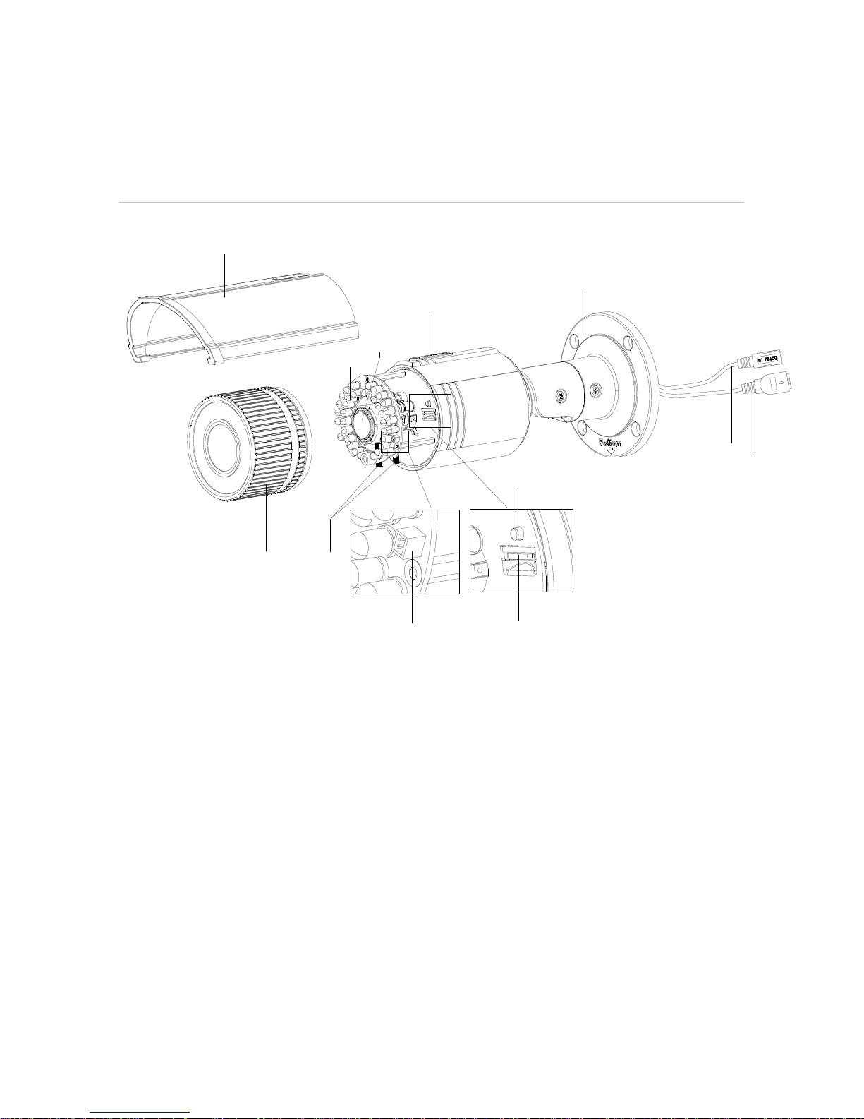
Overview
Figure 1: Camera overview
(1) Sun shield
(2) Front cover
(3) Zoom and focus lever
(4) IR LED
(5) Lens
(6) Air vent
(7) Video output interface
(8) Integrated bracket
(9) Reset button
(10) SD card slot
(11) Power interface
(12) Network interface
Note: To reset the default parameters to the camera, press and
hold the reset button and power on the camera. After powered,
continue to press and hold the reset button for another 10
seconds.
5
4
10
9
7
3
8
6
1
2
12
11
5
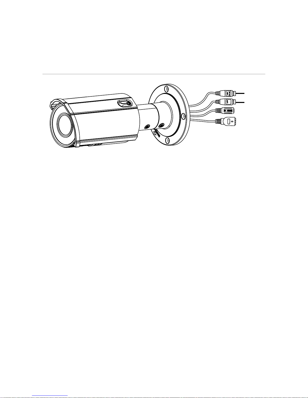
The bullet camera supports audio and alarm functions. The
interfaces are shown in Figure 2.
Figure 2: Audio and alarm interfaces
(1) Audio
(2) Alarm
(1)
(2)

6
Wiring
Wire your bullet camera as shown in Figure 3.
Figure 3: Wiring
Installation
To ensure the camera operates properly, install the camera
according to the instructions below.

7
Before you start
Make sure that the device in the package is in good
condition and all the assembly parts are included.
Make sure that all the related equipment is powered off
during the installation.
To determine the proper environmental operating conditions,
refer to Specifications on page 27.
Make sure the power supply matches the required voltage to
avoid damage.
If the product does not function properly, contact your dealer
or the nearest service center. Do not disassemble the
camera for repair or maintenance by yourself.
Make sure that the wall is strong enough to withstand three
times the weight of the camera.

8
To mount the SD card:
1. Rotate the TW M3 × 5 screw counterclockwise about 3 to
4 rounds to loosen it. Slide the sun shield according to the
arrow direction, as shown in the figure below (left).
Turn screw
 Loading...