

Clare Controls IP Network Camera User Manual

Clare Controls IP Network
Cameras User Guide
Doc ID 2014-12-343 • Rev 04


Copyright
© 29DEC14 Clare Controls, Inc. All rights reserved.
This document may not be copied in whole or in part or otherwise
reproduced without prior written consent from Clare Controls, Inc.,
except where specifically permitted under US and international
copyright law.
Trademarks and
patents
The Clare Controls IP Network Cameras name and logo are
trademarks of Clare Controls, Inc.
Other trade names used in this document may be trademarks or
registered trademarks of the manufacturers or vendors of the
respective products.
Version
This document applies to Clare Controls IP Network Cameras
version 01.
FCC compliance
This device complies with part 15 of the FCC Rules. Operation is
subject to the following two conditions: (1) This device may not
cause harmful interference, and (2) this device must accept any
interference received, including interference that may cause
undesired operation.
FCC compliance
This equipment has been tested and found to comply with the limits
for a digital device, pursuant to part 15 of the FCC Rules. These
limits are designed to provide reasonable protection against harmful
interference when the equipment is operated in a commercial
environment. This equipment generates, uses, and can radiate radio
frequency energy and, if not installed and used in accordance with
the instruction manual, may cause harmful interference to radio
communications. Operation of this equipment in a residential area is
likely to cause harmful interference in which case the user will be
required to correct the interference at his or her own expense.
This product and - if applicable - the supplied accessories too are
marked with "CE" and comply therefore with the applicable
harmonized European standards listed under the Low Voltage
Directive 2006/95/EC, the EMC Directive 2004/108/EC.
2002/96/EC (WEEE directive): Products marked with this symbol
cannot be disposed of as unsorted municipal waste in the European
Union. For proper recycling, return this product to your local supplier
upon the purchase of equivalent new equipment, or dispose of it at
designated collection points. For more information see:
www.recyclethis.info.
2006/66/EC (battery directive): This product contains a battery that
cannot be disposed of as unsorted municipal waste in the European
Union. See the product documentation for specific battery
information. The battery is marked with this symbol, which may
include lettering to indicate cadmium (Cd), lead (Pb), or mercury
(Hg). For proper recycling, return the battery to your supplier or to a
designated collection point. For more information see:
www.recyclethis.info.
Contact information
For contact information, see www.clarecontrols.com.

Disclaimer statement
“Underwriters Laboratories Inc. (“UL”) has not tested the performance or
reliability of the security or signaling aspects of this product. UL has only tested
for fire, shock or casualty hazards as outlined in UL’s Standard(s) for Safety,
UL60950-1. UL Certification does not cover the performance or reliability of the
security or signaling aspects of this product. UL MAKES NO
REPRESENTATIONS, WARRANTIES OR CERTIFICATIONS WHATSOEVER
REGARDING THE PERFORMANCE OR RELIABILITY OF ANY SECURITY OR
SIGNALING RELATED FUNCTIONS OF THIS PRODUCT.”

Content
Important information...1
Limitation of liability...1
Safety warnings and cautions...2
Advisory messages...3
System requirement...4
Network connection...5
Setting the network camera over a LAN...5
Wiring over a LAN...5
Detecting and changing the IP address...6
Setting the network camera over a WAN...7
Static IP connection...7
Connecting the network camera with static IP directly...7
Dynamic IP connection...8
Connecting the network camera via a modem...8
Access to the network camera...10
Accessing by web browsers...10
Wi-Fi settings...13
Configuring Wi-Fi connection in manage and ad-hoc modes...13
Wireless connection in ad-hoc mode...14
Security mode...15
WPA-personal and WPA2-personal mode:...16
WPA- enterprise and WPA2-enterprise mode:...16
Easy Wi-Fi connection with WPS function...17
PBC mode:...18
PIN mode:...18
IP property settings for wireless network connection...20
Live View...21
Live View page...21
Starting live view...22
Full-screen mode...22
Recording and capturing pictures manually...22
Operating PTZ control...23
PTZ control panel...23
Setting/calling a preset...24
Configuring Live View parameters...25
Clare Controls IP Network Camera User Guide i

Network camera configuration...26
Configuring local parameters...26
Configuring time settings...27
Configuring TCP/IP settings...29
Configuring port settings...30
Configuring PPPoE settings...30
Configuring DDNS settings...31
Configuring SNMP settings...33
Configuring 802.1X settings...34
Configuring QoS settings...35
Configuring FTP settings...35
Configuring UPnP settings...36
Configuring video settings...37
Configuring audio settings...39
Configuring ROI encoding...40
Configuring image parameters...40
Configuring display settings...40
Configuring OSD Settings...43
Configuring text overlay settings...44
Configuring privacy mask...45
Configuring picture overlay...46
Configuring and handling alarms...47
Configuring motion detection...47
Arming schedule for motion detection...48
Set the alarm actions for motion detection....49
Configuring video tampering alarm...49
Handling exception...50
Email sending triggered by alarm...51
Configuring snapshot settings...52
Uploading to FTP...52
Configuring other alarms...53
Configuring PTZ...55
Configuring the basic PTZ settings...55
Configuring the PTZ limit settings...56
Configuring the initial PTZ position...57
Configuring the PTZ park action...58
Configuring the PTZ privacy mask...58
Configuring a PTZ scheduled task...59
Clearing a PTZ configuration...61
Configuring the prioritize PTZ...61
ii Clare Controls IP Network Camera User Guide

Storage settings...62
Configuring NAS settings...62
Configuring recording schedule...63
Playback...67
Log searching...69
Others...70
Understanding camera capacity in an NVR...70
Streaming video types...70
Adjusting settings...71
Managing user accounts...71
Configuring RTSP authentication...73
Anonymous visit...73
IP address filter...74
Viewing device information...76
Maintenance...76
Rebooting the camera...76
Restoring default settings...77
Importing/exporting configuration files...77
Upgrading the system...78
RS-232 settings...78
RS-485 settings...79
Appendix 1...80
SADP software introduction...80
Description of SADP V 2.0...80
Search online devices manually...81
Modify network parameters...81
Appendix 2...82
Port mapping...82
Clare Controls IP Network Camera User Guide iii

iv Clare Controls IP Network Camera User Guide

Important information
Limitation of liability
To the maximum extent permitted by applicable law, in no event will Clare Controls, Inc.
be liable for any lost profits or business opportunities, loss of use, business interruption,
loss of data, or any other indirect, special, incidental, or consequential damages under
any theory of liability, whether based in contract, tort, negligence, product liability, or
otherwise. Because some jurisdictions do not allow the exclusion or limitation of liability
for consequential or incidental damages the preceding limitation may not apply to you.
In any event the total liability of Clare Controls, Inc. shall not exceed the purchase price
of the product. The foregoing limitation will apply to the maximum extent permitted by
applicable law, regardless of whether Clare Controls, Inc. has been advised of the
possibility of such damages and regardless of whether any remedy fails of its essential
purpose.
Installation in accordance with this manual, applicable codes, and the instructions of the
authority having jurisdiction is mandatory.
While every precaution has been taken during the preparation of this manual to ensure
the accuracy of its contents, Clare Controls, Inc. assumes no responsibility for errors or
omissions.
Clare Controls IP Network Camera User Guide 1
Safety warnings and cautions
Please pay attention to the following warnings and cautions.
Hazardous voltage may be present: Special measures and precautions
must be taken when using this device. Some voltages on the device may
present a hazard to the user. This device should only be used by employees
from our company with knowledge and training in working with devices that contain live
circuits.
Power supply hazardous voltage: AC mains voltages are present within the power
supply assembly. This device must be connected to a UL approved, completely
enclosed power supply, of the proper rated voltage and current. There are no user
serviceable parts inside the power supply.
System grounding (Earthing): To avoid shock, ensure that no AC wiring is exposed
and that the earth grounding is maintained. Ensure that any equipment to which this
device will be attached is also connected properly to wired, grounded receptacles.
Power connect and disconnect: The AC power supply cord is the main disconnect
device to mains (AC power). The socket outlet should to be installed near the
equipment and be easily accessible.
Installation and Maintenance: Do not connect/disconnect any cables or perform
installation/maintenance on this device during an electrical storm.
Power cord requirements: The connector that plugs into the wall outlet must be a
grounding-type male plug designed for use in your region. It must have certification by
an agency in your region. The connector that plugs into the AC receptacle on the power
supply must be an IEC 320, sheet C13, female connector. See the following website for
more information http://kropla.com/electric2.htm.
Lithium battery: This device contains a lithium battery. There is an explosion
risk if the battery is replaced with an incorrect type. Dispose of the used
batteries according to the vendor’s instructions and in accordance with local
environmental regulations.
2 Clare Controls IP Network Camera User Guide

Perchlorate material: Special handling may apply. See
www.dtsc.ca.gov/hazardouswaste/perchlorate. This notice is required by California
Code of Regulations, Title 22, Division 4.5, and Chapter 33: Best Management
Practices for Perchlorate Materials. This device includes a battery which contains
perchlorate material.
Thermal and mechanical injury: Some components such as heat sinks,
power regulators, and processors may be hot. Care should be taken to avoid
contact with these components.
Electromagnetic interference: This equipment has not been tested for compliance
with emission limits of the FCC and similar international regulations. This device is not,
and may not be, offered for sale or lease without authorization from the United States
FCC or its equivalent in other countries. It is prohibited to use this equipment in a
residential location. This equipment generates, uses, and can radiate radio frequency
energy. This can result in harmful interference to radio communications.
Lead content: Recycle this device in a responsible manner. Refer to
local environmental regulations for proper recycling; do not dispose of
device in unsorted municipal waste.
Advisory messages
Warnings
Input voltage should meet both the SELV (Safety Extra Low Voltage) and the Limited
Power Source with 24 VAC or 12 VDC according to the IEC60950-1 standard.
To reduce the risk of fire or electrical shock, do not expose this product to rain or
moisture.
This installation should be made by a qualified service person and should conform to
all the local codes.
Install blackout equipment in the power supply circuit for convenient supply
interruption.
Make sure that the ceiling can support more than 50 (N) Newton gravities.
Never attempt to disassemble the camera yourself. (We shall not assume any
responsibility for problems caused by unauthorized repair or maintenance.)
Clare Controls IP Network Camera User Guide 3

Cautions
Before using the camera, make sure the power supply voltage is correct.
Do not drop or subject the camera to physical shock.
Do not touch the sensor modules with your fingers. If cleaning is necessary, use a
clean cloth with a bit of ethanol and wipe it gently. If the camera will not be used for
an extended period, put the lens cap on to protect the sensor from dirt.
Do not aim the camera lens at strong light such as the sun or an incandescent lamp.
This can cause severe damage to the camera.
The sensor may be burned out by a laser beam. Make sure that the surface of the
sensor is not exposed to laser equipment.
Do not place the camera in extremely hot or cold temperatures (the operating
temperature should be between 14 to 140˚F (-10 to 60°C) or in dusty or damp
environments.
Good ventilation is required for a proper operating environment avoiding heat
accumulation.
Keep away from water or any liquid.
When returning, the camera should be in its original packing.
Improper use or replacement of the battery may result in explosion. Always use the
manufacturer recommended battery type.
System requirement
Operating system: Microsoft Windows XP SP1 and above version / Vista / Win7 /
Server 2003 / Server 2008 32 bits
CPU: Intel Pentium IV 3.0 GHz, or higher
RAM: 1 G or higher
Display: 1024 × 768 resolution, or higher
Web browser: Internet Explorer 6.0, and above; Apple Safari 5.02, and above; Mozilla
Firefox 3.5, and above; and Google Chrome 8, and above.
4 Clare Controls IP Network Camera User Guide
Network connection
If you want to set the network camera via a LAN (Local Area Network), refer to “Setting
the network camera over a LAN” on page 5.
If you want to set the network camera via a WAN (Wide Area Network), refer to “Setting
the network camera over a WAN” on page 7.
Setting the network camera over a LAN
To view and configure the camera via LAN, you must connect the network camera in
the same subnet as your computer. Install the SADP software to search for and change
the IP of the network camera.
Note: For the detailed introduction of SADP, refer to Appendix 1.
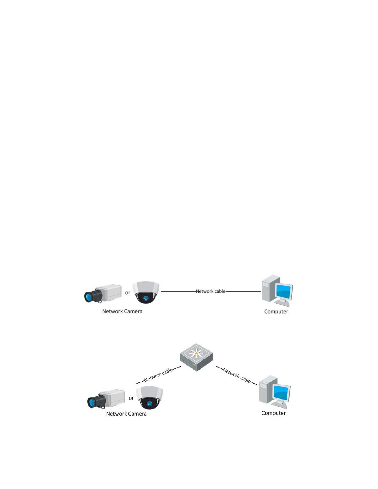
Wiring over a LAN
The following figures show the two ways for establishing the cable connection of a
network camera and a computer.
To test the network camera, connect it directly to the computer with a network cable, as
shown in Figure 1.
Refer to Figure 2 to set the network camera over a LAN, via a switch or using a router.
Figure 1: Connecting directly
Figure 2: Connecting via a switch or a router
Clare Controls IP Network Camera User Guide 5
Detecting and changing the IP address
You need the IP address to visit the network camera.
To detect and change the IP address:
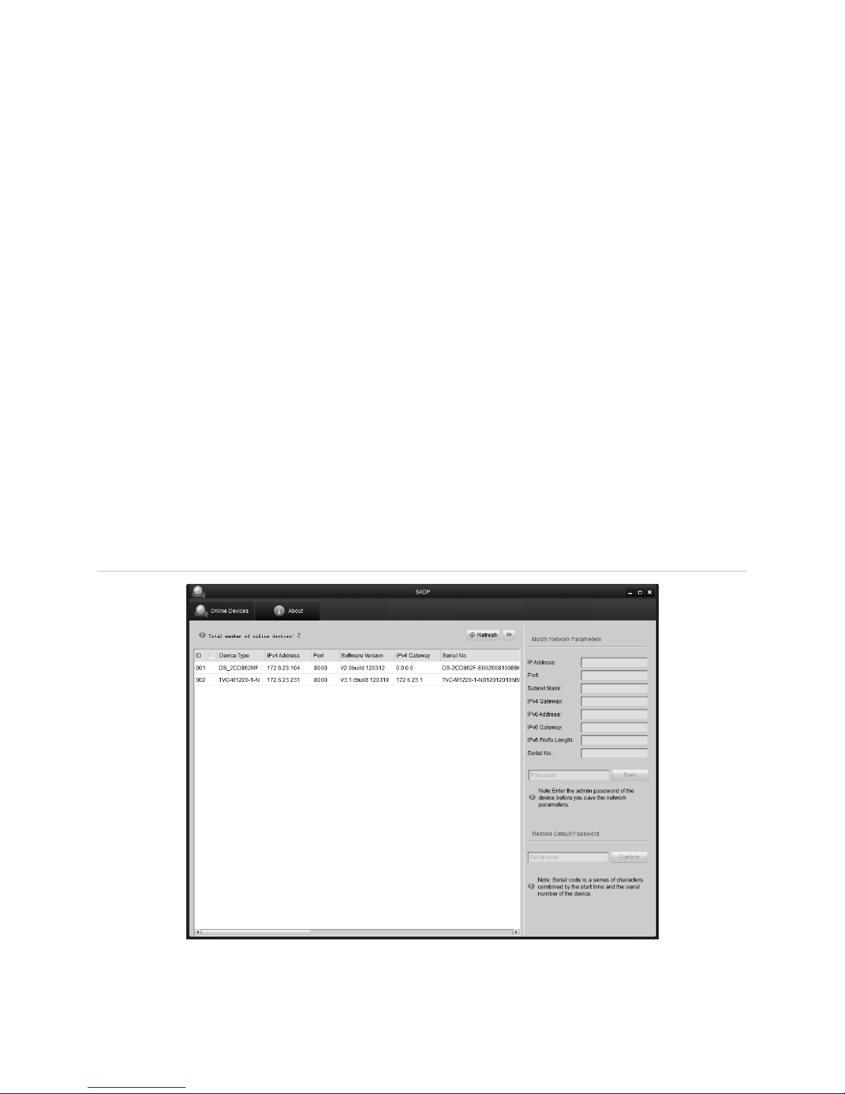
1. To get the IP address, you can choose one of the following methods:
Use SADP, a software tool which can automatically detect the online network
cameras in a LAN. List the device information including IP address, subnet mask,
port number, device serial number, device version, etc., shown in Figure 3.
Use the client software to list all online devices. Refer to the user manual or client
software for detailed information.
2. Change the IP address and subnet mask to match your computer.
3. Enter the IP address of the network camera in the address field of the web browser
to view the live video.
Notes
The default IP address is 192.168.1.250 and the port number is 8000. The
default user name is clareadmin, and password is secure7.
For accessing the network camera from different subnets, set the gateway for the
network camera after you have logged in.
Figure 3: SADP interface
6 Clare Controls IP Network Camera User Guide
Setting the network camera over a WAN
This section explains how to connect the network camera to a WAN with a static IP or a
dynamic IP.
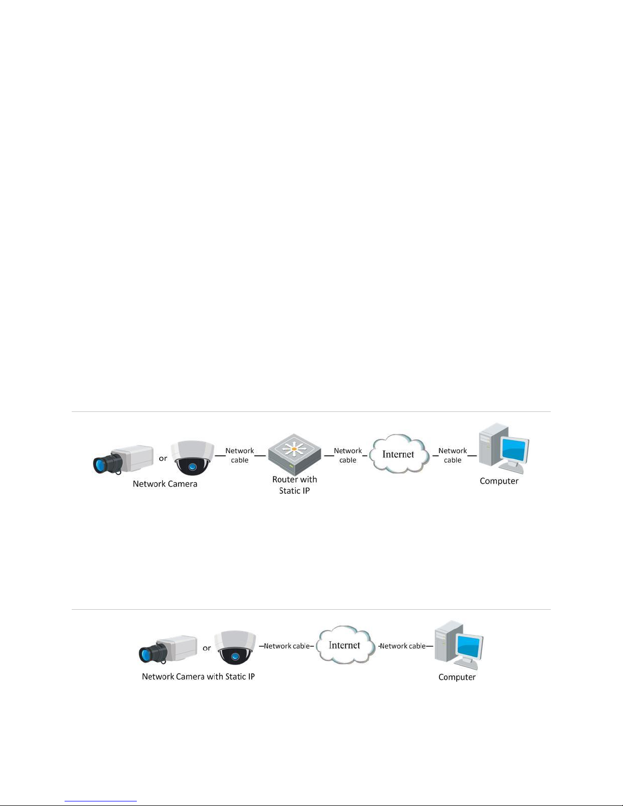
Static IP connection
Apply a static IP from an ISP (Internet Service Provider). With the static IP address, you
can connect the network camera via a router or connect it to a WAN directly.
To connect the network camera via a router:
1. Connect the network camera to the router.
2. Assign the LAN IP address, subnet mask, and gateway.
3. Save the static IP in the router.
4. Set port mapping – for example, 80, 8000, 8200, and the 554 ports. The steps for
port mapping vary based on router. Call the router manufacturer for assistance with
port mapping.
Note: Refer to Appendix 2 for detailed information about port mapping.
5. Visit the network camera through a web browser or the client software.
Figure 4: Accessing the camera though a router with a static IP
Connecting the network camera with static IP directly
You can save the static IP in the camera and connect it directly to the internet without
using a router.
Figure 5: Accessing the camera with static IP directly
Clare Controls IP Network Camera User Guide 7
Dynamic IP connection
Apply a dynamic IP from an ISP. With the dynamic IP address, you can connect the
network camera to a modem or a router.
To connect the network camera via a router
1. Connect the network camera to the router.
2. In the camera, assign a LAN IP address, subnet mask, and gateway.
3. In the router, set the PPPoE user name and password.
4. Set port mapping, e.g., 80, 8000, 8200 and the 554 ports. The steps for port
mapping vary based on router. Call the router manufacturer for assistance with port
mapping.
Note: Refer to Appendix 2 for detailed information about port mapping.
5. Apply a domain name from a domain name provider.
6. Configure the DDNS settings in the setting interface of the router.
7. Visit the camera via the applied domain name.
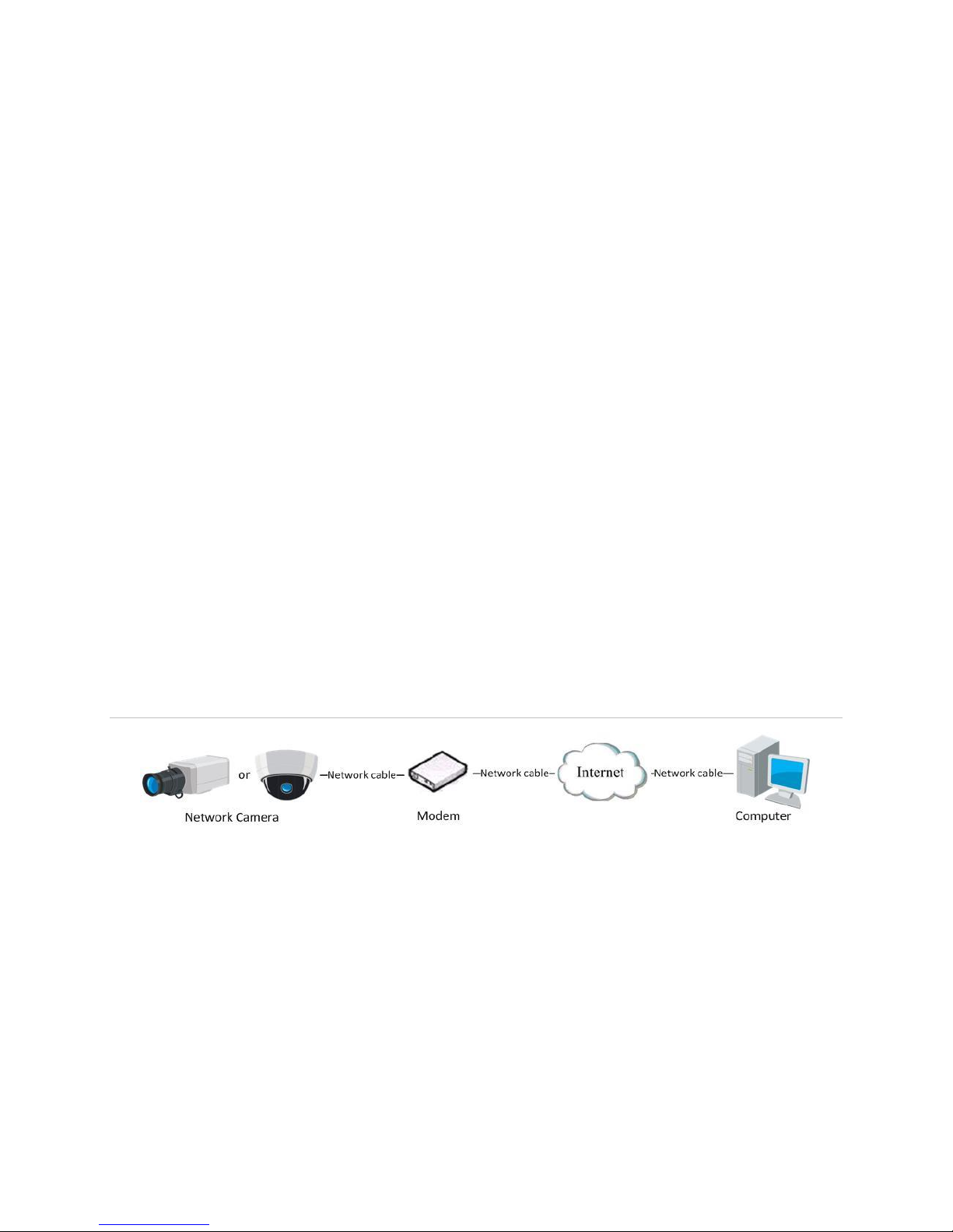
Connecting the network camera via a modem
If the camera supports the PPPoE auto dial-up function, the camera will get a public IP
address. This is done by ADSL dial-up, after the camera is connected to a modem.
Configure the PPPoE parameters of the network camera.
Figure 6: Accessing the camera with dynamic IP
Note: The obtained IP address is dynamically assigned via PPPoE, so the IP address
will change after every reboot. To stop this from happening, obtain a domain name from
a DDNS provider – for example, www.example.myclarevision.com. Follow the below
steps for normal and private domain name resolution.
8 Clare Controls IP Network Camera User Guide
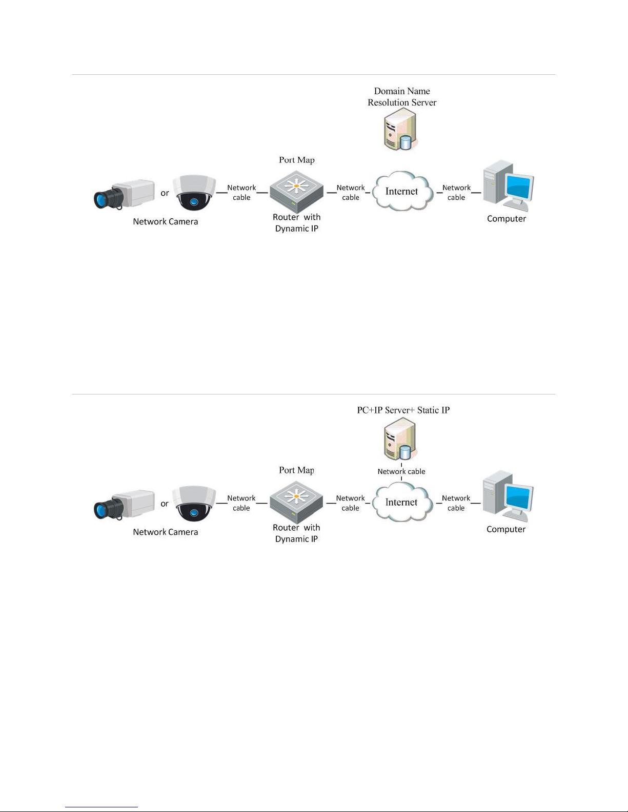
Figure 7: Normal domain name resolution
Steps:
1. Obtain and apply a domain name from a domain name provider.
2. Configure the DDNS settings in the DDNS settings interface of the network camera,
and then click Save.
3. When prompted, reboot for the settings to take effect.
4. Configure the DDNS settings of the camera via the applied domain name.
Figure 8: Private domain name resolution
Steps:
1. Install and run the IP server software on a computer with a static IP.
2. Access the network camera through a LAN with a web browser or the client
software.
3. Enable DDNS and select the IP Server as the protocol type, and then click Save.
4. When prompted, reboot for the settings to take effect.
Clare Controls IP Network Camera User Guide 9
Access to the network camera
Accessing by web browsers
Accessing the network camera through a web browser lets you view the camera feed
and configure the cameras settings.
To access the camera by web browsers:
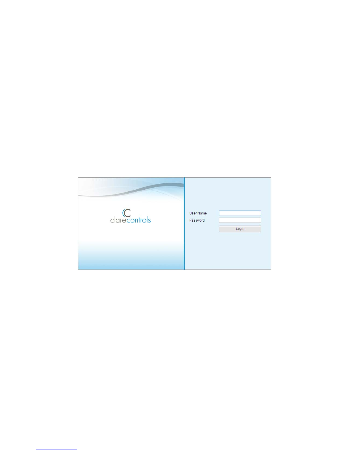
1. Open the web browser.
2. In the address field, enter the IP address of the network camera (e.g.,
192.168.1.250), and then press Enter.
This brings you to the login interface.
3. Enter the user name and password, and then click Login.
Note: The default user name is clareadmin; the password is secure7
10 Clare Controls IP Network Camera User Guide
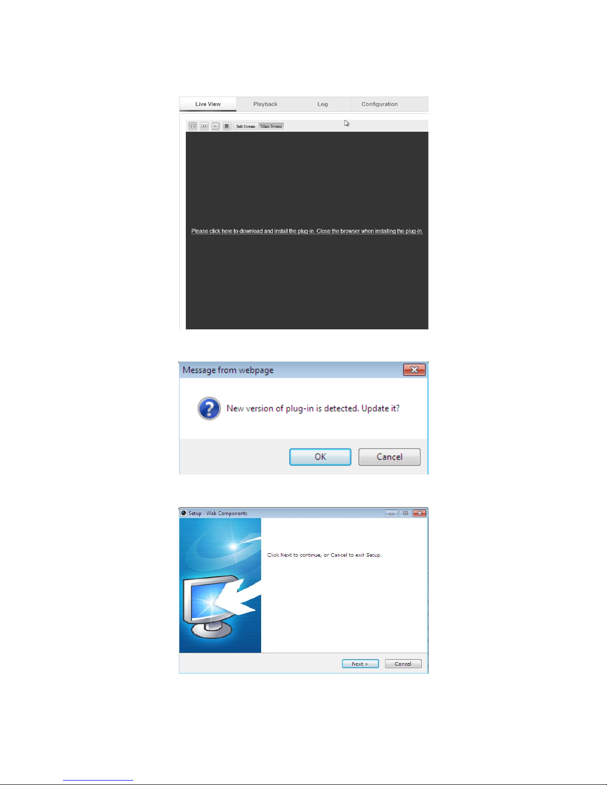
4. Install the plug-in, if prompted, and follow the installation prompts before viewing the
live video and operating the camera.
5. Click OK.
6. Click Next.
Clare Controls IP Network Camera User Guide 11
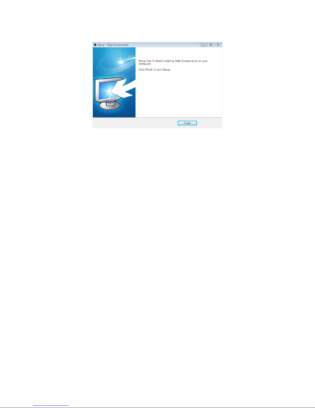
7. Click Finish.
Note: You may need to close the web browser to install the plug-in. After installing
the plug-in, reopen the web browser and log in.
12 Clare Controls IP Network Camera User Guide
Wi-Fi settings
You do not need to use cables when connecting to the wireless network.
Note: This chapter is only applicable for the cameras with a Wi-Fi module built-in, like
the Clare Controls 1.3 MP Budget Mini-Dome Camera with Wi-Fi.
Configuring Wi-Fi connection in manage and ad-hoc modes
A wireless network must be configured.
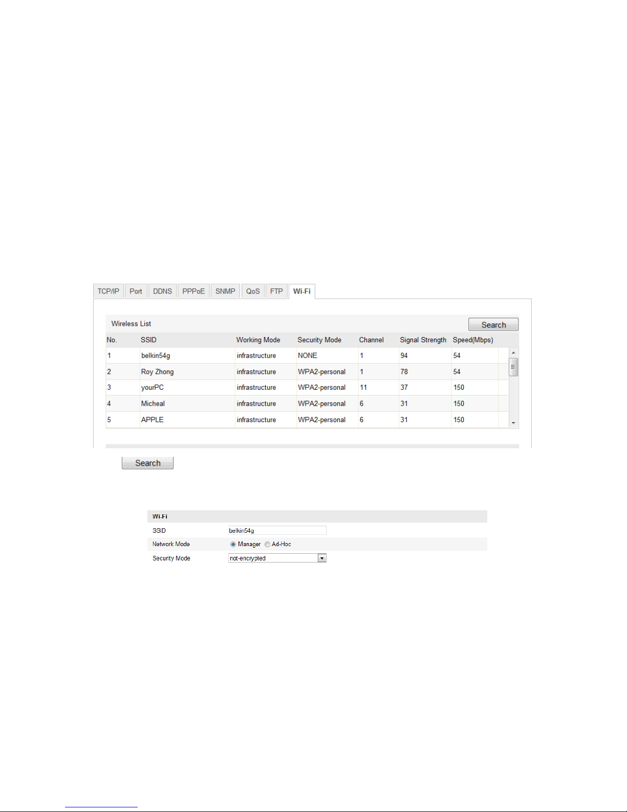
To configure a wireless connection in Manage Mode:
1. Enter the Wi-Fi configuration interface.
Configuration > Camera Configuration > Network > Wi-Fi
2. Click to search the online wireless connections.
3. Click to select a wireless connection on the list.
4. Select the checkbox to select the Network Mode as Manager. The Security Mode
and the network Encryption Type are automatically selected when you choose the
wireless network, do not change it manually.
Note: These parameters need to match those of the router.
5. Enter the password to connect the wireless network. The password should be that of
the wireless network connection you set on the router.
Clare Controls IP Network Camera User Guide 13
Wireless connection in ad-hoc mode
If you choose the Ad-Hoc mode, you do not need to connect the wireless camera via a
router. The camera broadcast the wireless signal. Connect the camera directly to the
PC with a network cable.
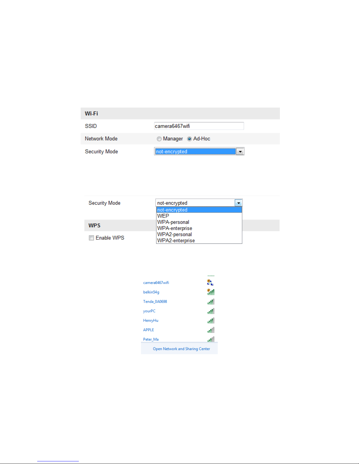
To configure a wireless connection in ad-hoc mode:
1. Choose Ad-Hoc mode.
2. Customize the SSID for the camera.
3. Choose the Security Mode of the wireless connection.
4. Enable the wireless connection function for your PC.
5. On the PC, search the network to see see the SSID of the camera listed.
6. Choose the SSID and connect.
14 Clare Controls IP Network Camera User Guide
Security mode
Figure 9: Security Mode Options
You select the Security Mode; not-encrypted, WEP, WPA-personal, WPA-enterprise,
WPA2-personal, and WPA2-enterprise.
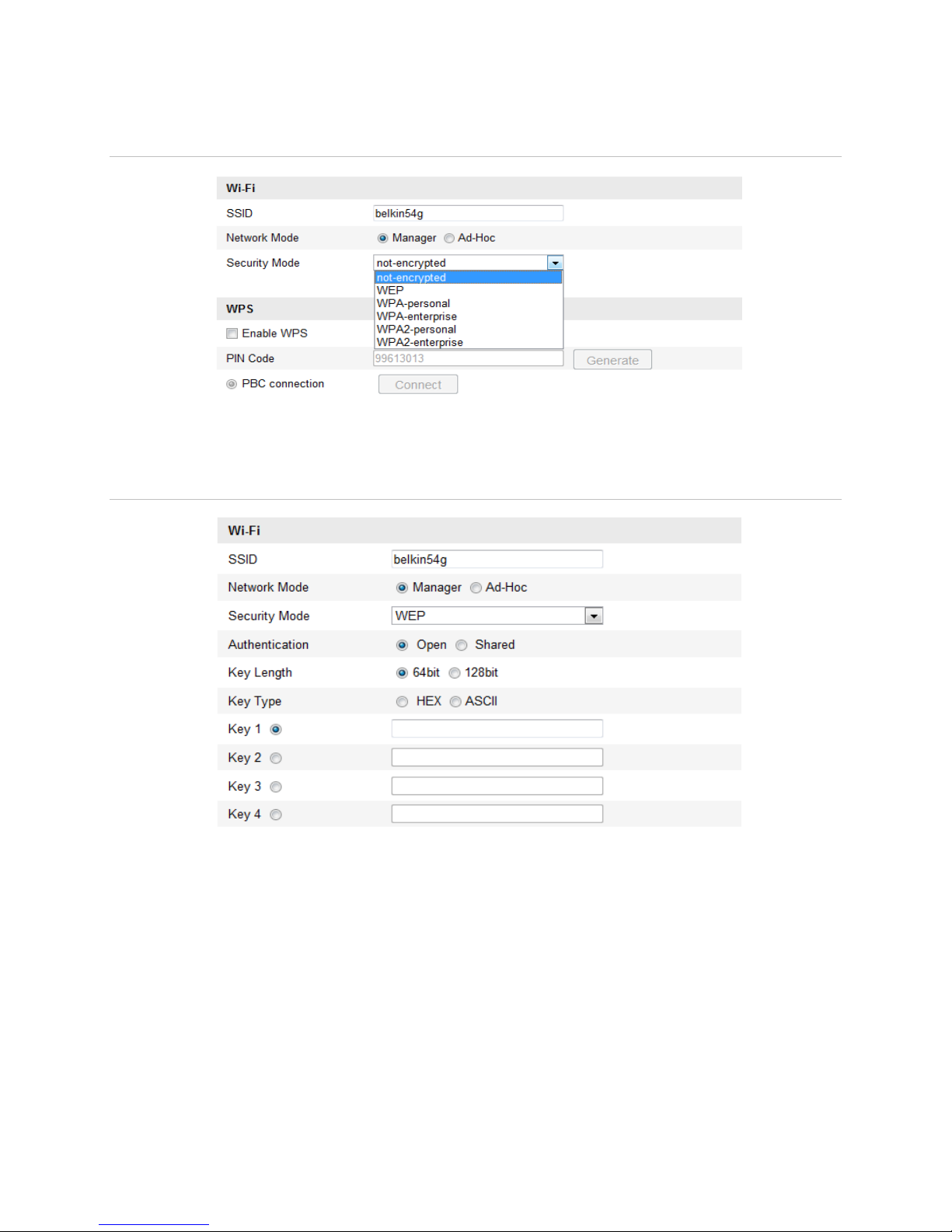
Figure 10: WEP Mode
Authentication - Select Open or Shared Key System Authentication, depending on
the method used by the access point. Not all access points have this option.
Key Length - This sets the length of the key used for the wireless encryption,
64 or 128 bit. The encryption key length can sometimes be shown as 40/64 and
104/128.
Key Type - The key types depend on the access point being used. The following
options are available:
o HEX - Allows you to manually enter the hex key.
o ASCII - In this method the string must be exactly 5 characters for 64 bit WEP and
13 characters for 128 bit WEP.
Clare Controls IP Network Camera User Guide 15

WPA-personal and WPA2-personal mode:
Enter the required pre-shared key for the access point, a hexadecimal number or a
passphrase.
Figure 11: Wi-Fi key 1
WPA- enterprise and WPA2-enterprise mode:
Choose the type of client/server authentication being used by the access point:
EAP-TLS or EAP-PEAP.
Figure 12: EAP-TLS
16 Clare Controls IP Network Camera User Guide
EAP-TLS
Identity - Enter the user ID to present to the network.
Private key password – Enter the password for your user ID.
EAPOL version - Select the version used (1 or 2) in your access point.
CA certificates - Upload a CA certificate to present to the access point for
authentication.
EAP-PEAP:
User Name - Enter the user name to present to the network.
Password - Enter the password of the network.
PEAP Version - Select the PEAP version used at the access point.
Label - Select the label used by the access point.
EAPOL version - Select version (1 or 2) depending on the version used at the
access point.
CA Certificates - Upload a CA certificate to present to the access point for
authentication.
Easy Wi-Fi connection with WPS function
WPS (Wi-Fi Protected Setup) refers to the configuration of the encrypted connection
between the device and the wireless router. The WPS makes it easy to add new
devices to an existing network without entering long passphrases. There are two modes
of the WPS connection; the PBC mode and the PIN mode.
Note: If you enable the WPS function, you do not need to configure the parameters or
know the key of the wireless connection.
Figure 13: WPS PBC configuration
Clare Controls IP Network Camera User Guide 17

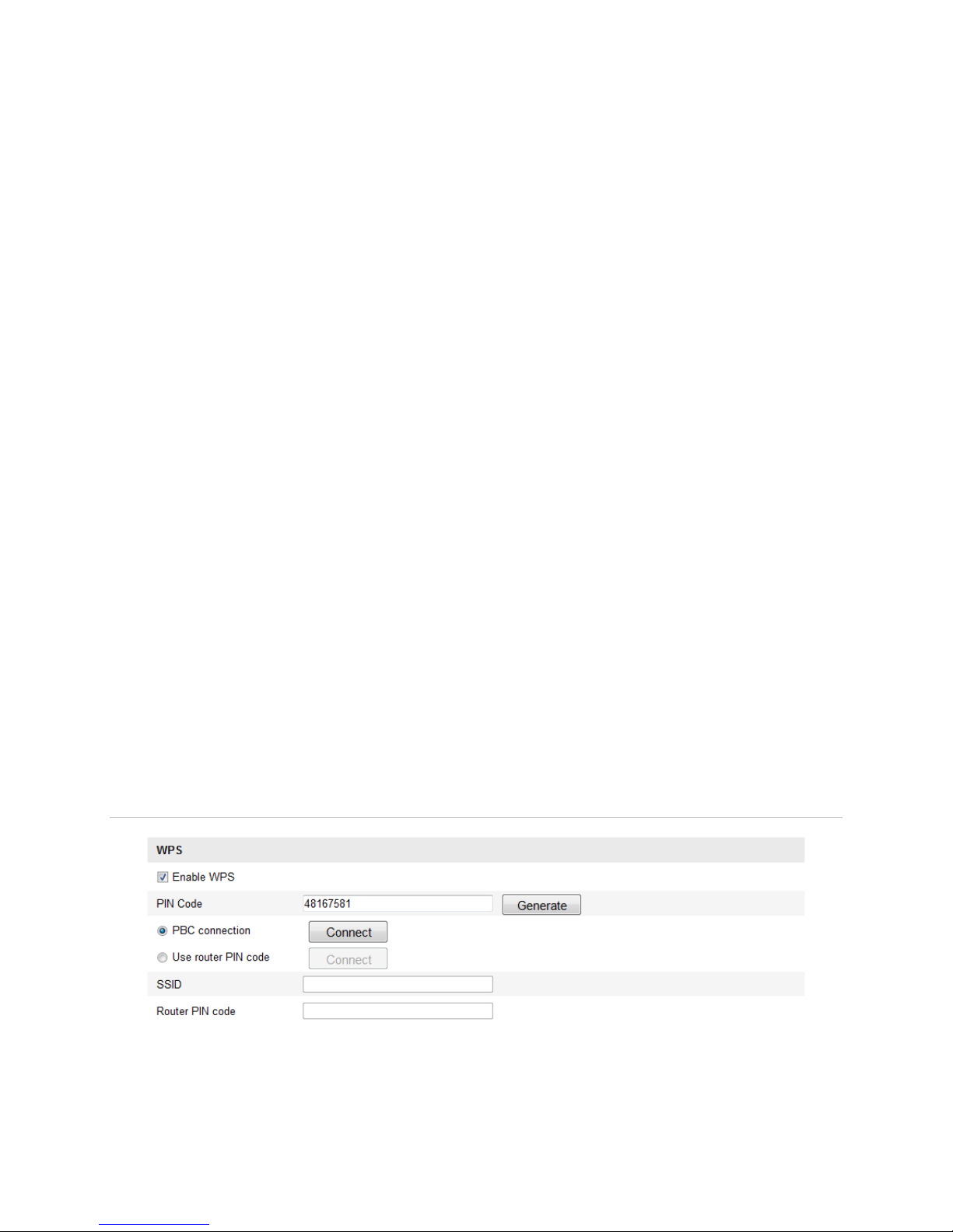
PBC mode:
PBC (Push-Button-Configuration) allows the user to push a button, on both the Access
Point and the new wireless client device for configuration.
To enable the PBC function:
1. Select the Enable WPS checkbox.
2. Choose the connection mode as PBC.
Note: The Access Points much each support PBC mode.
3. Check the Wi-Fi router for a WPS button. Push the button, and the indicator near the
button starts flashing. This means the WPS function is enabled. For detailed
operation, see the user guide of the router.
4. Push the WPS button on the camera.
If there is no WPS button on the camera, click the virtual button on the web interface
to enable the PBC function.
5. Click Connect.
When the PBC mode is enabled in both the router and the camera, the camera and the
wireless network connect automatically.
PIN mode:
The PIN (Personal Identification Number) mode requires the pin from either a sticker or
the display on the new wireless device. This PIN must then be entered to connect to the
network.
To enter PIN mode:
1. Choose a wireless connection on the list and the SSID is shown.
18 Clare Controls IP Network Camera User Guide

2. Select Use router Pin code.
3. If the PIN is generated from the router, enter the PIN in the Router PIN code field.
4. Click Connect.
- or -
You can generate a PIN code using the camera. The expiration time for the PIN
code is 120 seconds.
5. Click Generate.
6. Enter the code to the router in the PIN Code field.
Clare Controls IP Network Camera User Guide 19
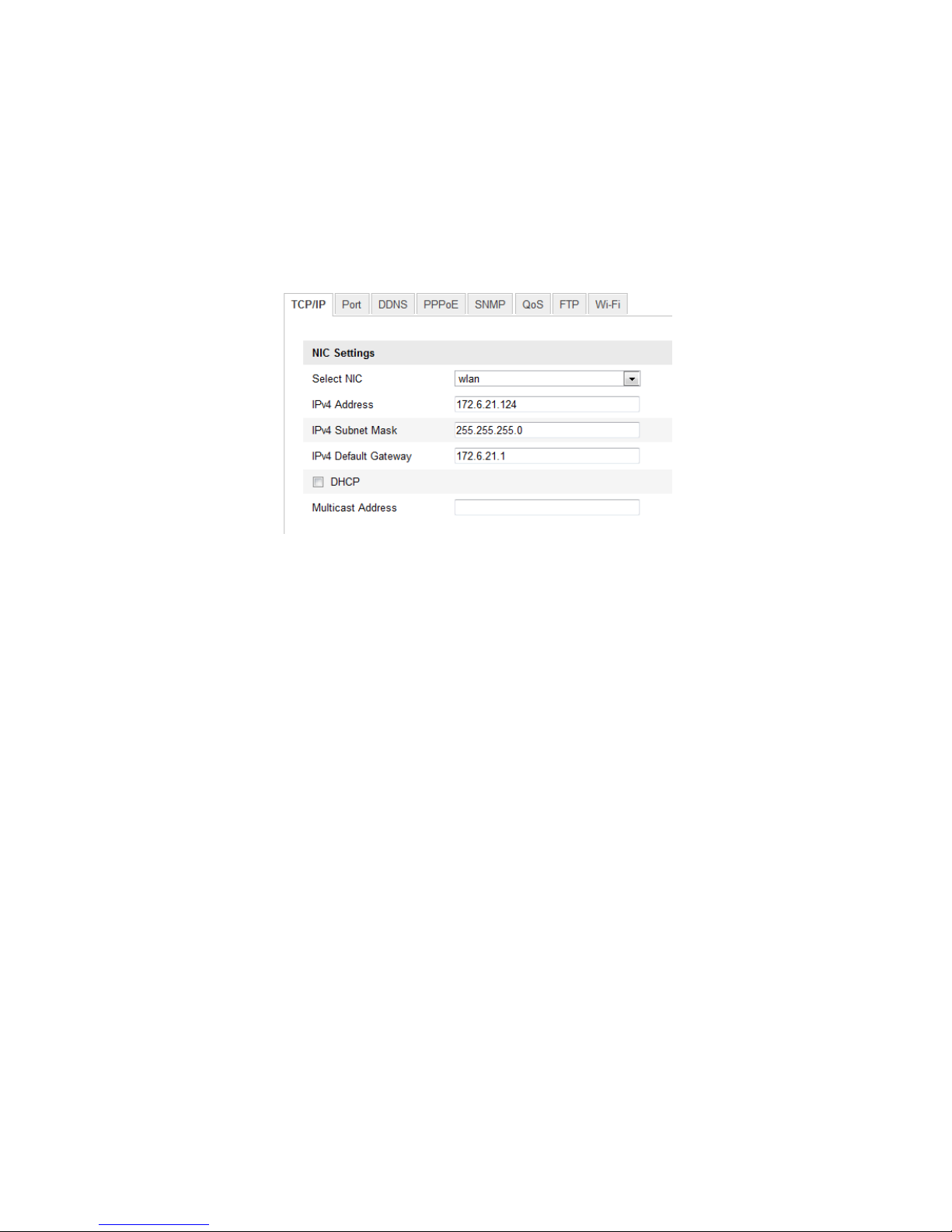
IP property settings for wireless network connection
The default IP address of the wireless network interface controller is 192.168.1.64.
When you connect the wireless network you can change the default IP.
To change the default IP:
1. Enter the TCP/IP configuration interface.
Configuration > Camera Configuration > Network > TCP/IP
2. Set Select NIC as wlan.
3. Customize the IPv4 address, the IPv4 Subnet Mask, the IPv4 Default Gateway, and
the Multicast Address.
The setting use the same process as the LAN.
If you do not want to assign the IP address, select the checkbox to enable the DHCP.
20 Clare Controls IP Network Camera User Guide
 Loading...