

Clare Controls HDBaseT 16x16, HDBaseT 32x32 User Manual
Doc ID - 753 • Rev 02
Modular Matrix Switch
User Guide
Models HDBaseT 16x16 and 32x32
Last modified: 09/29/16

Copyright
© 09SEP16 Clare Controls, LLC. All rights reserved.
This document may not be copied in whole or in part or
otherwise reproduced without prior written consent from
Clare Controls, LLC., except where specifically permitted
under US and international copyright law.
Trademarks and
patents
Modular Matrix Switches, Models CM-MM161610-HD and
CM-MM323210-HD name is a trademark of Clare
Controls, LLC.
Other trade names used in this document may be
trademarks or registered trademarks of the manufacturers
or vendors of the respective products.
Manufacturer
Clare Controls, LLC.
7519 Pennsylvania Ave., Suite 104
Sarasota, FL 34243, USA
Contact information
For contact information, see www.clarecontrols.com.

Modular Matrix Switch User Guide i
Content
Important information...ii
Limitation of liability...ii
Introduction...1
About the switch system...1
Features...1
Package contents...2
Switcher models...2
Signal cards...2
Front panel...3
Front panel button control...4
External connections...5
Input and output connectors...5
Changeable cards introduction and installation...6
Connecting with the RS-232 communication port...10
Connecting with a computer...10
System diagram...11
IP and RS-232 control protocol...12
Detailed examples...15
Specifications...17
Changeable cards...18
Troubleshooting and maintenance...20
Safety operation guide...21
After-sales service...22
Warranty information...22

ii Modular Matrix Switch User Guide
Important information
Limitation of liability
To the maximum extent permitted by applicable law, in no event will Clare
Controls, Inc. be liable for any lost profits or business opportunities, loss of use,
business interruption, loss of data, or any other indirect, special, incidental, or
consequential damages under any theory of liability, whether based in contract,
tort, negligence, product liability, or otherwise. Because some jurisdictions do
not allow the exclusion or limitation of liability for consequential or incidental
damages the preceding limitation may not apply to you. In any event the total
liability of Clare Controls, Inc. shall not exceed the purchase price of the
product. The foregoing limitation will apply to the maximum extent permitted by
applicable law, regardless of whether Clare Controls, Inc. has been advised of
the possibility of such damages and regardless of whether any remedy fails of
its essential purpose.
Installation in accordance with this manual, applicable codes, and the
instructions of the authority having jurisdiction is mandatory.
While every precaution has been taken during the preparation of this manual to
ensure the accuracy of its contents, Clare Controls, Inc. assumes no
responsibility for errors or omissions.

Modular Matrix Switch User Guide 1
Introduction
About the switch system
The HDBaseT 16x16 and 32x32 matrix switches are high-performance video and
audio modular matrix switches. Various changeable cards make matrix switches
flexible and an all-in-one solution for different projects. The matrix switches can
support different video signals with cross switching. Every video or audio signal is
transmitted and switched independently; this will cause the least signal attenuation,
so that the output signal keeps its high fidelity.
Two series of changeable cards work with matrix switches, input card MOD-4I series
and output card MOD-4O series. All the cards support hot plug-and-play. Users can
choose the right card for different applications. Different signal cards are used for
processing different video signal, including HMDI, VGA, and HDBaseT.
The matrix switches can be used for different projects, because of the changeable
card design. It is the combination solution for multimedia conference rooms, control
rooms, broadcasting rooms, and shopping centers. The matrix switches can handle
all the audio and visual management, including the switching, driving, and scaling.
Features
Modular chassis with configurable I/O slots, ranging from 16x16 to 32x32
Various I/O cards, includes HDMI, VGA, and HDBaseT cards (compatible with
YUV, YC and CVBC) to configure any matrix
True cross-point switching for any input to any output, regardless signal format
Advanced EDID management, three ways to guarantee maximum compatibility
Supports HDMI 1.4a and 3D
Integrated HDBaseT technology
I/O cards works directly with CATx or a fiber optic extender
Ultra-switching for an instantaneous display, ensuring the transition runs
smoothly
Unique pixel-accurate and re-clocking technology provides exceptional output
transmission and accurate timing
Controlled via buttons, RS-232, TCP/IP, IR, also compatible with third-party
controls
Field-upgradeable and hot-swappable, friendly to use and maintain
HDCP compliant
LCD display

2 Modular Matrix Switch User Guide
Package contents
1 x modular matrix switch (with empty slots and empty covers)
1 x RS-232 cable
1 x IR remote (battery is not included)
2 x power cord
4 x plastic cushions
1 x user manual
Switcher models
Table 1: Title of the table
Model
Height
Maximum slot
Power
supplies
RS-232
control
Network
control
16x16
3U
4 input card slots and
4 output card slots
Dual
√
Optional
32x32
5U
8 input card slots and
8 output card slots
Dual
√
Optional
Signal cards
To meet different situation and users, the signal cards are classified into the
following models.
Input cards
Table 2: Input cards
Models
Inputs
Signal Format
CM-MOD-HDI10
4
HDMI
CM-MOD-VGI10
4
VGA
CM-MOD-HDBI10
4
HDBaseT
Modular Matrix Switch User Guide 3
Table 3: Output cards
Models
Outputs
Signal Format
CM-MOD-HDO10
4
HDMI
CM-MOD-VGO10
4
VGA
CM-MOD-HDBO10
4
HDBaseT
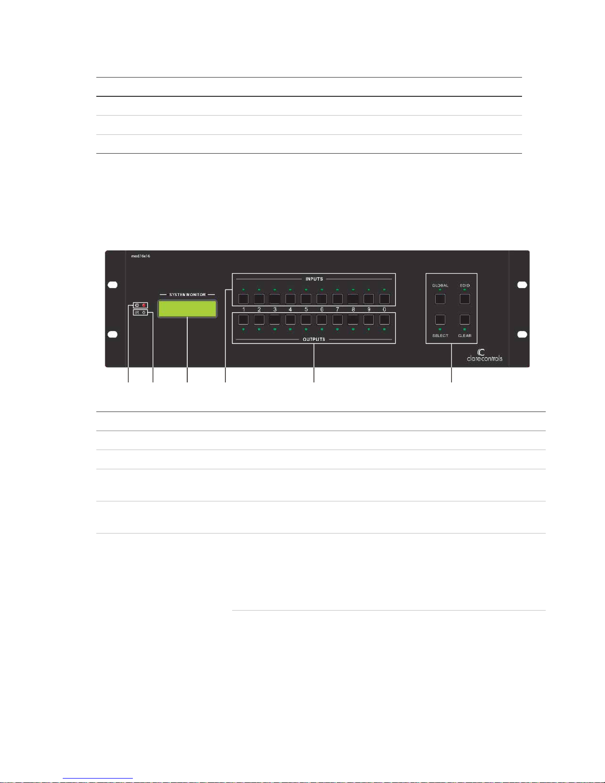
Front panel
The 16x16 and 32x32 switches share the same function buttons, but only differ in
case height.
(1) Power indicator
Power 'on' indicator light.
(2) IR receiver
IR receive window.
(3) LCD indicator
Shows real-time system status.
(4) INPUTS
Allows direct selection of the input channel from 1 to 16 or
1 to 32.
(5) OUTPUTS
Allows direct selection of the output channel from 1 to 16 or
1 to 32.
(6) FUNCTION
GLOBAL: Used to transfer video and audio signal (HDMI) of an
input channel to all output channels.
Example: To transfer HDMI signal from input channel 7 to all
output channels, press the buttons as follows: Input “0” “7” +
“GLOBAL” + “Select”.
EDID: Used to manually control EDID management.
Example: To learn the EDID data of the display on output
channel 2 to input channel 3, press the buttons as follows:
"EDID" + Input "0" "3" + Output "0" "2".
(1) (2) (3) (4) (5) (6)

4 Modular Matrix Switch User Guide
SELECT: Used to transfer video and audio signal (HDMI) from
an input to an output.
Example To transfer both the video and audio signals from input
channel 3 to output channel 4, press the buttons as follows:
Input “0” "3" + Output “0” "4" + "SELECT".
CLEAR: Clear an operation, such as switching output channel,
studying EDID data before it comes into effect. Meanwhile, the
switcher returns to the previous state.
Front panel button control
Users can control the switch rapidly and directly using its front panel buttons. The
following is a brief operation guide to operating the front panel buttons.
Switching I/O connection
Function: Switch I/O connection. It is important to know that input and output
channels should be double-digit. For example, input 01 represents input 1.
Format: Input Channel + Output Channel + Select
Examples
To transfer input 1 to output 11, press the following.
(input) 0 1 + (output) 1 2 + Select.
To transfer signals from input 1 to all output channels, press the following.
0 1 + Global + Select.
EDID Management
Function: Enable the input channel to capture and learn the EDID data of an output.
Format: EDID + Input Channel + Output Channel + Select
Example
To enable input 1 to learn the EDID data of output 2, press the following.
EDID + (input) 0 1 + (output) 0 2 + Select.
Clear the previous operation
Function: Clears the previous operations before pressing Select to enforce it.
Pressing Clear only erases the operations not confirmed by pressing Select.

Modular Matrix Switch User Guide 5
Notes
Input Channel: Fill with the number of input channel to be controlled,
Output Channel: Fill with the number of output channels to be controlled. Press
Global to select all the outputs.
The input and output channels on the rear panel are counting from left to right,
and top to bottom.
The input delay time between two numbers of every input and output channel
must be less than 5 seconds; otherwise, the operation will be cancelled.
End every operation by pressing Select to confirm the operation.
External connections
Input and output connectors
The 16x16 switch has 8 card slots (max.) in the rear panel, including 4 input slots
and 4 output slots.
The 32x32 switch has 16 card slots (max.) in the rear panel, including 8 input slots
and 8 output slots.
Note: The cards in the pictures are for reference, only. You can choose different
cards in different cases, each supporting plug-and-play.
 Loading...