

Clare Controls CM-MT4410-BT-70 User Manual
2014-12-352 • Rev 03
HDBaseT 4x4 Matrix Switcher
Model CM-MT4410-BT-70


2014-12-352 • Rev 03
Copyright
© 11DEC14 Clare Controls, Inc. All rights reserved.
This document may not be copied in whole or in part or
otherwise reproduced without prior written consent from
Clare Controls, Inc., except where specifically permitted
under US and international copyright law.
Trademarks and
patents
HDBaseT 4x4 Matrix Switcher, Model CM-MT4410-BT-70
name is a trademark of Clare Controls, Inc.
Other trade names used in this document may be
trademarks or registered trademarks of the manufacturers
or vendors of the respective products.
Manufacturer
Clare Controls, Inc.
7519 Pennsylvania Ave., Suite 104, Sarasota, FL 34243,
USA
Version
This document applies to HDBaseT 4x4 Matrix Switcher
User Guide, Model CM-MT4410-BT-70 version 1.
Contact information
For contact information, see www.clarecontrols.com.


HDBaseT 4x4 Matrix Switcher User Guide i
Content
Important information...iii
Limitation of liability...iii
Introduction...1
Features...1
Package contents...2
Product appearance...4
Front panel...4
Rear panel...5
Connection with RS232 communication port...6
Twisted pair cable connection...7
System connection...8
Usage precautions...8
System diagram...9
Connection procedure...10
System applications...10
Application solution...11
System operations...11
I/O control...11
Learn EDID data...12
EDID setting...12
Status check...13
Clear operation...13
IR control...14
IR remote...14
IR operations...15
RS232 control...19
TCP/IP control...25

ii HDBaseT 4x4 Matrix Switcher User Guide
Specifications...30
Troubleshooting and maintenance...32
Safety operation guide...34
After-sales service...35

HDBaseT 4x4 Matrix Switcher User Guide iii
Important information
Limitation of liability
To the maximum extent permitted by applicable law, in no event will Clare
Controls, Inc. be liable for any lost profits or business opportunities, loss of use,
business interruption, loss of data, or any other indirect, special, incidental, or
consequential damages under any theory of liability, whether based in contract,
tort, negligence, product liability, or otherwise. Because some jurisdictions do not
allow the exclusion or limitation of liability for consequential or incidental damages
the preceding limitation may not apply to you. In any event the total liability of
Clare Controls, Inc. shall not exceed the purchase price of the product. The
foregoing limitation will apply to the maximum extent permitted by applicable law,
regardless of whether Clare Controls, Inc. has been advised of the possibility of
such damages and regardless of whether any remedy fails of its essential
purpose.
Installation in accordance with this manual, applicable codes, and the instructions
of the authority having jurisdiction is mandatory.
While every precaution has been taken during the preparation of this manual to
ensure the accuracy of its contents, Clare Controls, Inc. assumes no responsibility
for errors or omissions.


HDBaseT 4x4 Matrix Switcher User Guide 1
Introduction
The CM-MT4410-BT-70 is an HDBaseT matrix switch with four HDMI inputs, four
HDBaseT outputs (with two mirrored local HDMI outputs), four de-embedded stereo
audio outputs, and four de-embedded digital audio outputs. It enables cross-point
switching from any input to any output, and supports high-resolution 1080 P, 3D, and
4K*2K. The HDBaseT output works in conjunction with the CM-BT10-RX70 receiver, to
transmit HDMI, IR, RS232, and PoC (Power over Cable) over a Cat5e/Cat6 cable up to
230 ft. (70 m).
Features
HDTV compatible with high definition transmission resolution up to 1920 x 1200 at
60 Hz, 1080 P at 24 Hz/60 Hz, and supports 3D.
HDCP compliant and DVI compatible, supporting DVI1.0.
Auto and manual control of EDID and HDCP management
HDBaseT outputs allow transmission of HDMI, RS232 and IR up to 230 ft. (70 m)
via Cat5e/Cat6 cable, allowing source equipment to be centrally located and
shared between multiple display devices.
PoC provides power for all the HDBaseT receivers connected to the HDBaseT
outputs, which eliminates the need for additional power supplies at the receiver
location.
Matrix switch is controllable via TCP/IP, RS232, IR (remote included), or the front
panel.
Individual IR inputs allow infrared commands to be sent to remote equipment via
HDBaseT receivers; additionally, 'IR All In' allows a single IR input to be shared to
all connected HDBaseT receivers, reducing the number of IR outputs required by
a control system.
IR received at the remote located HDBaseT receivers can be routed to the
centrally located source equipment via the 'IR Out' ports.
Supports PCM, Dolby, and DTS5.1 surround
LCD indicator shows connection status, switching status, HDCP status, and
output resolution.

2 HDBaseT 4x4 Matrix Switcher User Guide
Package contents
1 x CM-MT4410-BT-70 HDBaseT 4x4 matrix switch
2 x removable brackets for rack mounting of the switch
10 x screws
1 x power adapter (48 VDC)
1 x power cord
1 x IR remote
4 x 3.5 mm male mono to 3.5 mm male stereo IR adapter cable for use with a
central control system
1 x RS232 (male/female) cable for connection to a control system
8 x captive screw connectors
4 x plastic feet for shelf mounting
1 x user manual
Notes: Please verify that the product and all the accessories are included. If not,
contact your dealer.

HDBaseT 4x4 Matrix Switcher User Guide 3
4 HDBaseT 4x4 Matrix Switcher User Guide
Product appearance
Front panel
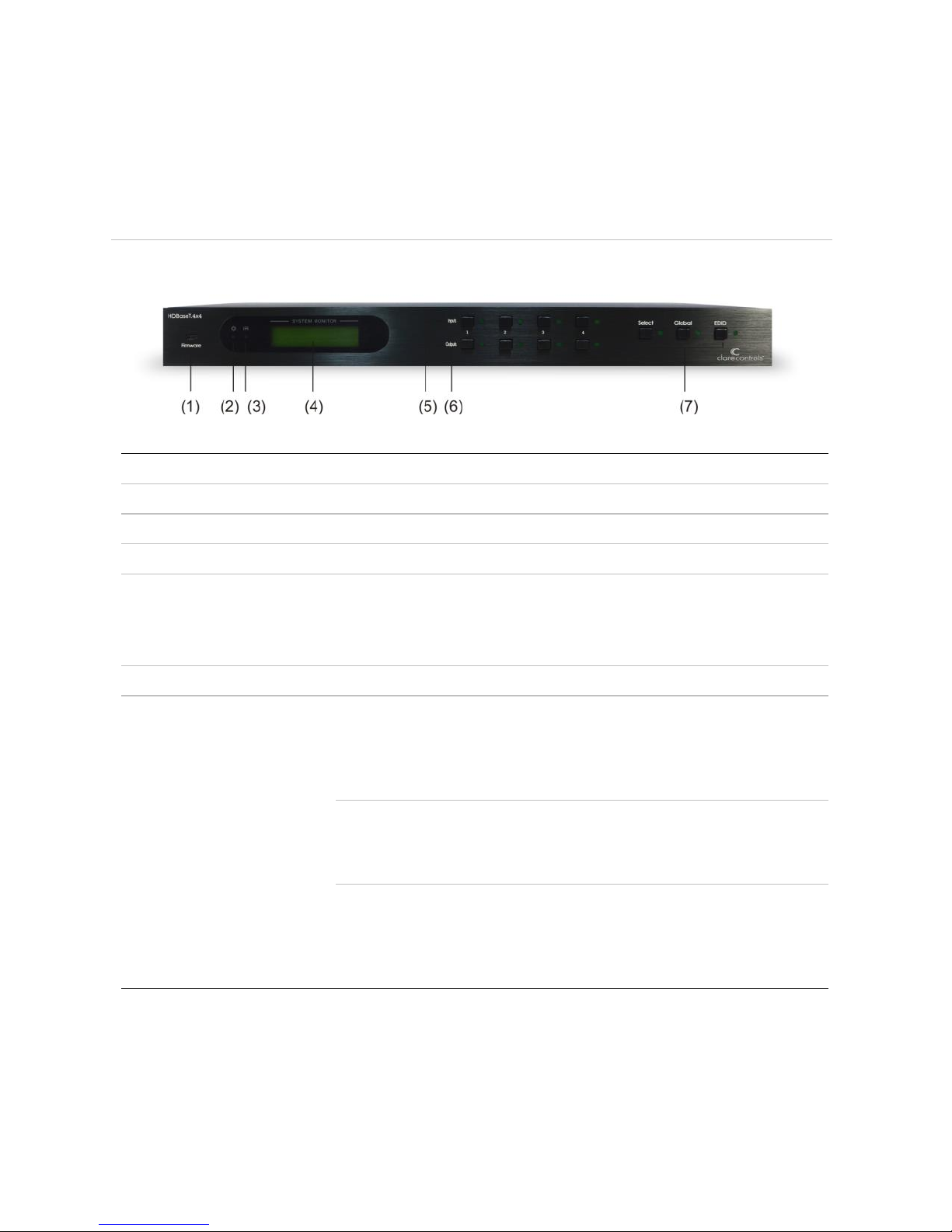
Figure 1: Front panel of HDBaseT 4x4 Matrix Switcher
(1) Firmware
Micro USB port for updating firmware.
(2) Power indicator
Power 'on' indicator light.
(3) IR receiver
IR receive window.
(4) LCD indicator
Shows real-time system status.
(5) INPUTS/Menu
buttons
Normal mode: Input buttons range from 1 to 4.
Inquire mode: Press and hold “SELECT” for 3 seconds to enter
this mode. Press ◄► to change menus and ▲▼ to change
selection.
(6) Outputs
Output buttons, ranging from 1 to 4.
(7) Function buttons
SELECT button: Used to transfer HDMI and IR signal from an
input to an output.
Example To transfer both HDMI and IR signals from input channel
1 to output channel 3, press the buttons in this order:
“1”, “Select”, “3”.
GLOBAL button: Used to select all input to all outputs.
Example To transfer both HDMI and IR signals from all input
channels to all output channels, press the buttons in this order:
“1”, “GLOBAL”
EDID management button: Manually capture and copy the
EDID data from the output device to the input port.
Example To capture and copy the EDID data from output
channel 4 to input channel 2, press the buttons in this order:
“EDID”, “2”, “4”
HDBaseT 4x4 Matrix Switcher User Guide 5
Using the front control panel, press the buttons to directly control the switcher. Follow
the format below.
Input Channel (1-4) + SELECT + Output Channel (1-4)
This will route the HDMI signal and IR from the selected input to the selected output.
Rear panel
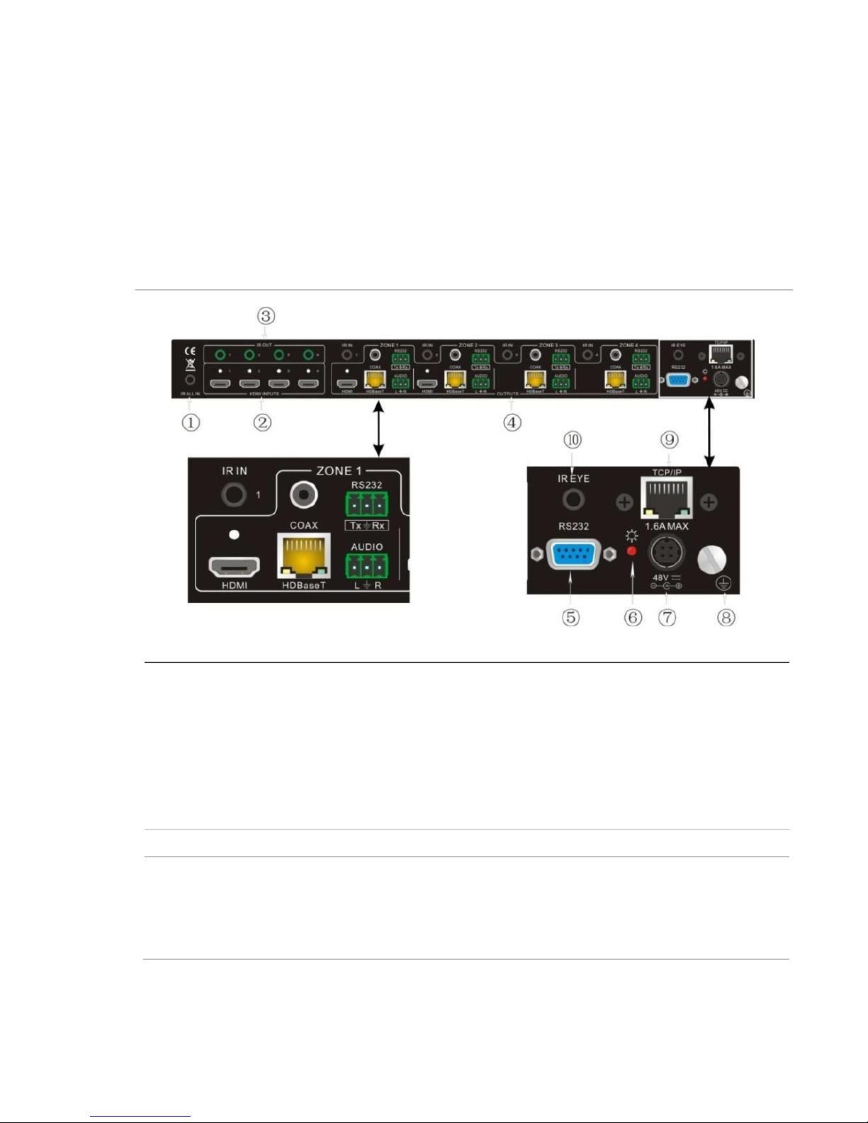
Figure 2: Rear panel of HDBaseT 4x4 Matrix Switcher
(1) IR ALL IN
Global IR control: An IR input signal in this port will pass through to
all connected HDBaseT receivers simultaneously.
Note: This applies to all IR inputs on this switch.
When using a control system, such as Clare Controls, Crestron, or
URC, the 3.5 mm female mono to 3.5 mm male stereo adapter
cable (included) must be used. The female mono end connects to
the control system. The male stereo end connects to the
CM-MT4410-BT-70.
(2) HDMI INPUTS
Type A female HDMI connectors.
(3) IR OUT
An IR signal transmitted via HDBaseT from any of the connected
receivers can be use on any of these outputs for an IR emitter to
control source equipment. These IR OUTs make up an IR matrix
with the IR INs on the HDBaseT receivers. They can be switched in
conjunction with the AV signal, or can be switched separately.
6 HDBaseT 4x4 Matrix Switcher User Guide
(4) OUTPUTS
IR IN: An IR signal input is transmitted via HDBaseT to the
corresponding receiver and is available for an IR emitter connected
to the receiver's IR OUT port.
HDMI: Mirrored HDMI output for local use.
COAX: HDMI de-embedded digital audio output.
HDBaseT: Connects to the HDBT IN on the CM-BT10-RX70
receiver. Supports transmission of HDMI, bi-directional IR and
RS232 and PoC (power-over-cable) up to 230 ft. (70 m).
RS232: RS232 port for communication with the RS232 port on
corresponding HDBaseT receiver.
AUDIO: HDMI de-embedded stereo audio output.
(5) RS232
The serial port for unit control, 9-pin female connector.
(6) Power indicator
Indicator light is on when the switch is powered.
(7) 48 VDC
Connection for external 48 VDC power supply.
(8) GROUND
Bonding point to ensure equipment is properly grounded.
(9) TCP/IP
TCP/IP port for control of the switch via IP.
(10) IR EYE
Allows direct connection for IR control, thus eliminating the need for
a front mounted emitter.
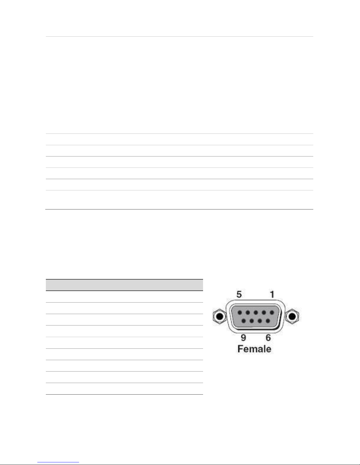
Connection with RS232 communication port
The CM-MT4410-BT-70 HDBaseT matrix switch can be controlled by the front panel,
IR, or RS232. RS232 control is via the rear RS232 communication port. It is a
female 9-pin D connector. The pin definitions are listed in the table below.
Table 1: RS232 connection definitions
No.
Pin
Function
1
N/u
Unused
2
Tx
Transmit
3
Rx
Receive
4
N/u
Unused
5
Gnd
Ground
6
N/u
Unused
7
N/u
Unused
8
N/u
Unused
9
N/u
Unused
 Loading...