

Clare Controls CLR-CVP-B2DB50-ODIW Quick Start Manual
DOC ID - 1563 • Rev 09 1 / 17
Clare Video Doorbell Quick Start Guide
Content
Introduction...1
Included...2
Clare Video Doorbell power requirements...2
Wi-Fi signal strength requirements...3
Installation...3
(Optional) Installing the resistor and power booster...6
Creating a ClareVision Plus account...7
Setting up the doorbell in the ClareVision Plus app...12
Understanding the ClareVision Plus app icons...13
Configuring the motion detection area...13
Troubleshooting and light status...16
Warranty Information...17
Support...17
Last modified: 01/23/19
Introduction
Thank you for choosing Clare Controls. In today’s competitive market place, we
can appreciate that you have many choices for your home automation needs.
This document is intended as a quick-start guide, not a full product guide. For
more information, view the full ClareVision Plus Camera User Guide (DOC ID
1430 Rev 02).
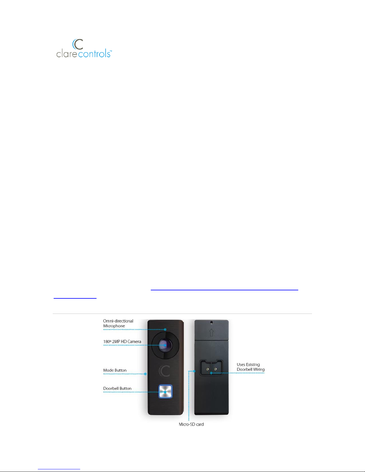
Figure 1: Clare Video Doorbell
DOC ID - 1563 • Rev 09 2 / 17
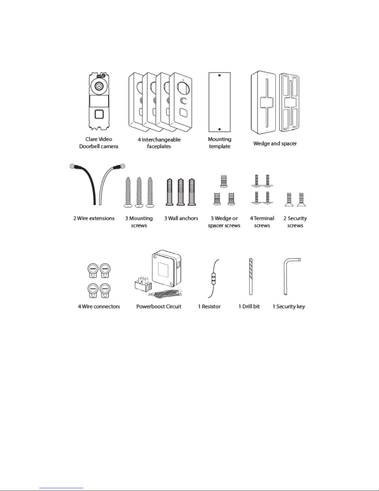
Included
The below items are included with the Clare Video Doorbell.
Clare Video Doorbell power requirements
The Clare Video Doorbell only works with mechanical doorbells that use 1624VAC power.
Note: To learn your current doorbell’s voltage, consult the original doorbell
packaging or a licensed electrician.
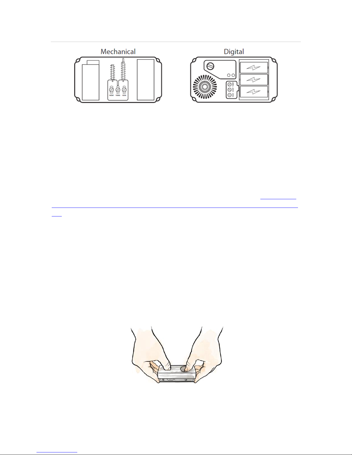
Mechanical versus digital doorbells
Listen to the tone the doorbell makes when ringing it, the tone determines if your
doorbell mechanical or digital. If it makes the standard ding-dong sound, it is
most likely a mechanical doorbell. If your doorbell plays a different tone or
melody, it’s most likely a digital doorbell. Digital doorbells are not currently
supported.
DOC ID - 1563 • Rev 09 3 / 17
Figure 2: Mechanical versus digital doorbell
Wi-Fi signal strength requirements
The Clare Video Doorbell must be connected to a 2.4GHz network and requires
a minimum -60dBm Wi-Fi signal strength at the installation location.
We recommend downloading a Wi-Fi analysis tool for your phone or tablet to
check signal strength. Stand at the doorbell installation location and test the WiFi strength. If a -60dBM signal or better is not achievable, we recommend
installation of a Wi-Fi range extender or Wireless Access Point (WAP) to ensure
proper video and audio streaming.
For a list of recommended Wi-Fi signal strength apps and tools, see Clare Video
Doorbell: Wi-Fi Signal Strength Apps and Tools Tech Bulletin (DOC ID 1608 Rev
02).
Installation
Before starting installation, make sure to shut off the doorbell’s power supply at
the breaker panel.
To install the Clare Video Doorbell:
1. Remove the existing doorbell and disconnect the wires connected to the
screws on the back.
2. Remove the Clare Video Doorbell’s faceplate by firmly holding the doorbell
and gently pressing down on the doorbell button and edge of the camera lens
bare.
DOC ID - 1563 • Rev 09 4 / 17
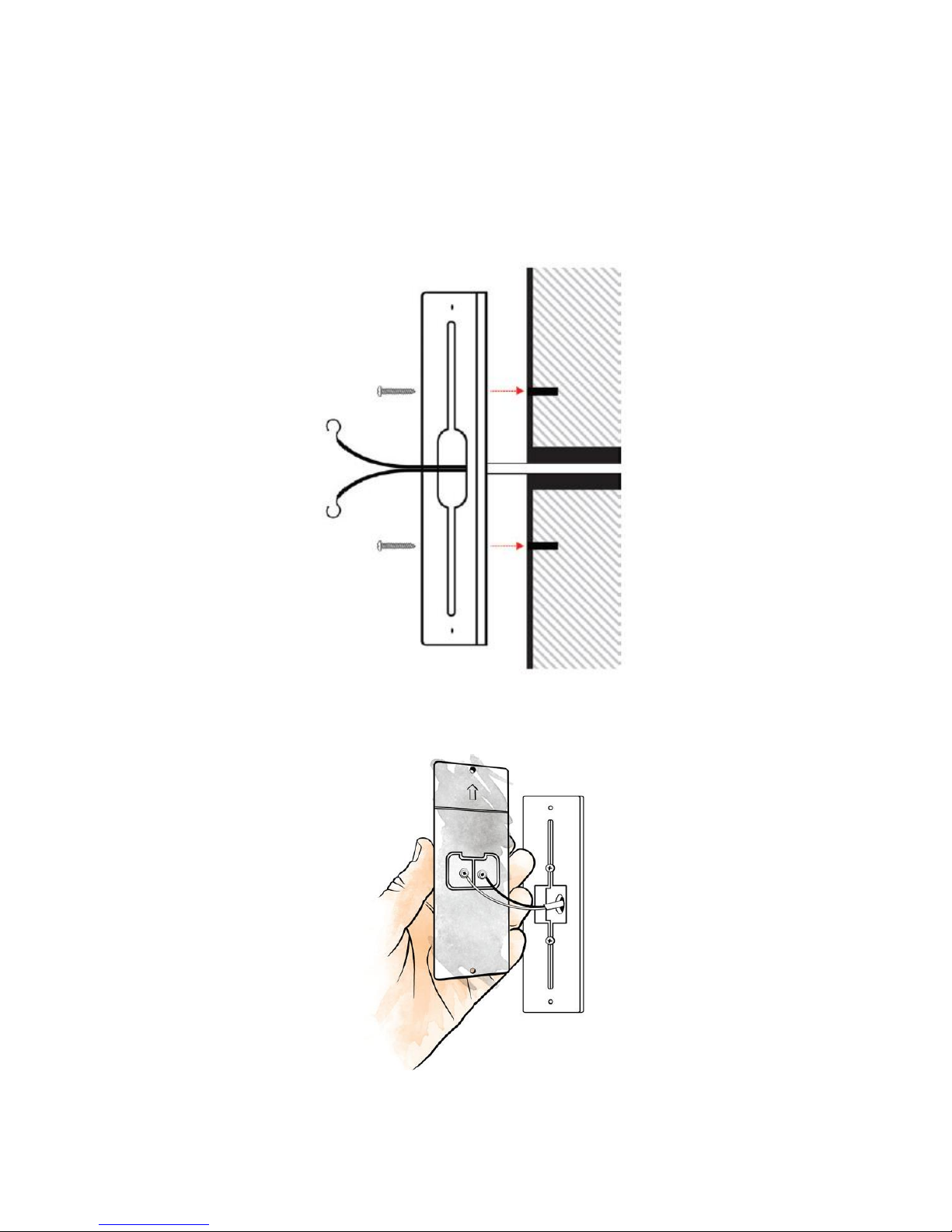
3. Mount the supplied spacer or wedge plate to the doorbell location using the
supplied wedge/space screws.
Note: The angled wedge plate can be used to change the viewing angle of
the doorbell.
Make sure to pull the doorbell wires through the center of the wedge
plate/spacer.
4. Connect the existing doorbell wires to the leads on the back panel of the
doorbell.
DOC ID - 1563 • Rev 09 5 / 17
If the existing wiring is not long enough, follow the instructions below to
extend the wiring.
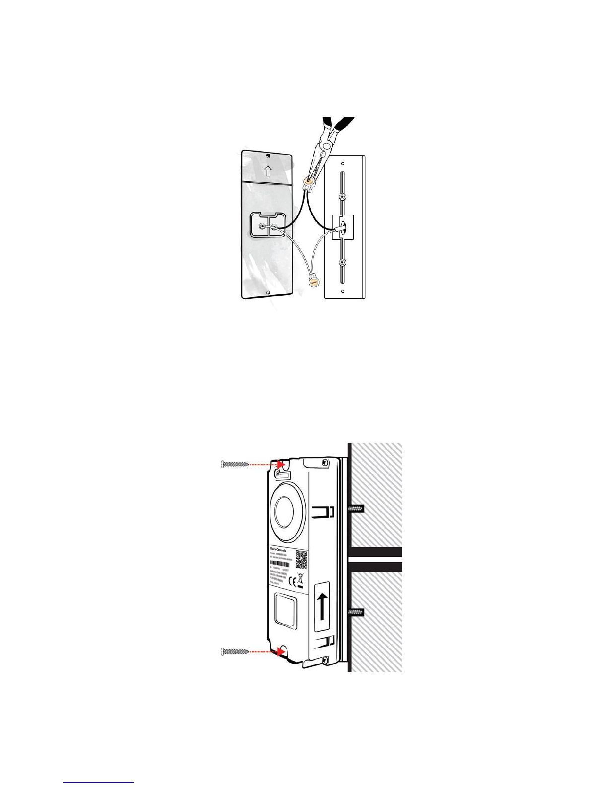
a. Insert the wires into the provided connectors.
b. Use pliers to snap the button into place.
Notes
• Do not strip the wires, the connectors pierce the insulation.
• The 2 wires used to power the doorbell can be connected to either
terminal.
5. Install the doorbell using the supplied mounting screws.
6. Restore power at the breaker, and then follow the instructions to setup the
doorbell in the ClareVision Plus app.
DOC ID - 1563 • Rev 09 6 / 17
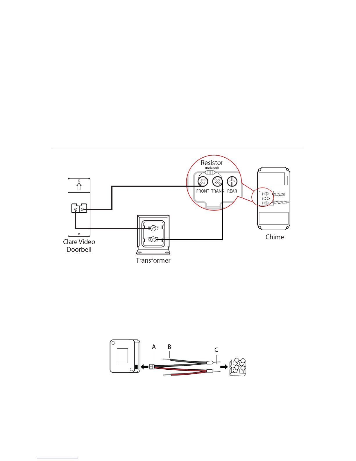
(Optional) Installing the resistor and power booster
The resistor can be installed when using a mechanical chime to eliminate
potential doorbell buzzing, and the power booster improves doorbell sound.
To install the resistor:
1. Wrap the ends of the supplied resistor around the terminals on the doorbell.
2. Verify proper installation by ringing the doorbell.
Note: Connecting the resistor in the wrong direction does not harm either
device, but results in the doorbell not ringing correctly. To correct this
mistake, reverse the direction of the resistor.
Figure 3: Resistor installation
To install the supplied power booster:
1. Using a small flat head screwdriver, loosen the set screws on the supplied
screw terminal.
2. Connect end C of the black and red wires to the screw terminal, then connect
end A of each wire to the provided power booster then re-tighten set screws
on the screw terminal.
 Loading...