

Clare Controls CLIQ.host Installation Sheet
© 08DEC14 Clare Controls, Inc. 1 / 3 Doc ID 2014-12-613 • REV 06
CLIQ.host Controller Installation Sheet
Description
The Clare Controls CLIQ.host controller provides all device
management services to AppModules, supports all Clare user
interface services, and acts as the gateway to the ClareCloud
for system updates. The controller comes complete with the
ClareOS and all AppModules preloaded.
Note: Models, and their appearance, are subject to change
without any prior notice.
WARNING: Any changes or modifications made to this product
not expressly authorized by the manufacturer could void the
user’s right to operate this device.
Unpacking the CLIQ.host
Remove all contents from the CLIQ.host packaging and ensure
you have the following items.
• 1 × CLIQ.host device
• 1 × power supply
• 3 × terminal connectors
• 1 × terminal connector jig
• 2 × RJ12 to DB-9 connectors (null modem)
• 6 × IR emitters
• 1 × Z-Wave antenna and extender cable
• 4 × rubber foot covers
Record the device’s UUID number (labeled on the bottom of
the device) on the line below, or scan the QR code (also on the
label) with a scanning app, and then email the number to your
system programmer. Your system programmer will need this
UUID information to configure the CLIQ.host device.
UUID: __________________________________
Do not use this UUID for more than one account.
WARNING: Do not apply power to the CLIQ.host until
installation is complete. Failure to do so may result in bodily
injury and/or damage to the equipment.
Installation
The CLIQ.host can be set on a rack shelf, or located in any
room near your devices.
Connecting devices to the CLIQ.host
After placing your CLIQ.host, make the connections to your
other devices. Figures 1 and 2 identify the LEDs and ports on
the front and rear of the CLIQ.host. Refer to the documentation
that came with each of your other devices for detailed
information about connecting those devices to the CLIQ.host.
To connect the CLIQ.host:
1. Connect your serial devices (optional) to either of the two
RS-232 ports using using an RJ12 to RS-232 cable, or an
RJ12 to DB9 null modem cable (included). See Figure 2,
item 1. For RJ12 pinouts, see Figure 3.
2. Connect your IR devices (optional) to the 12-pin terminal
connector (included), and then insert the connector into
the port labeled “IR Outputs.” See Figure 2, item 2.
If your IR device comes with a 3.5 mm connector, you will
need to cut and strip the wires before connecting it to the
terminal connector.
Note: When connecting an IR emitter (included), attach
the striped wire to positive (+) and the black wire to
negative (-).
3. Connect a CS-BR-1 Streams Audio Bridge (optional) to a
USB port on the CLIQ.host. See Figure 2, item 3.
Note: The USB connection allows the CS-BR-1 to encode
up to three simultaneous audio streams onto the CobraNet
network.
4. Connect your digital I/O devices (optional) to the 8-pin
terminal connector, and then insert the terminal connector
into the port labeled “I/O.” See Figure 2, item 4.
5. When connecting devices, wire it such that ports 1 and 2
share the same 12 VDC power and ground and ports 3
and 4 share the same power and ground.
6. Use an Ethernet cable (not included) to connect your
CobraNet switch to the port labeled “CobraNet.” See
Figure 2, item 5.
2 / 3 Doc ID 2014-12-613 • REV 06
Note:
The CobraNet port is preset with the static IP
address 172.30.100.1. All CobraNet devices used on the
same subnet must use an address from 172.30.100.2 to
172.30.100.254.
7. Use an Ethernet cable (not included) to connect to your
data network switch to the port labeled “Ethernet.” See
Figure 2, item 6.
Notes
• The Network port is preset to DHCP. If you are using
the Streaming Media server in your project, a fixed IP
address is not required and should be configured as
“localhost.”
• If you are using a device, such as an RTI remote that
requires the controller to have a static IP, you must set
the static IP using a MAC/DHCP reservation on the local
router.
8. Connect relay contacts (e.g., garage door contacts) to the
6-pin terminal connector, and then insert the terminal
connector into the port labeled “Relay.” See Figure 2,
item 7.
9. Screw the Z-Wave antenna or optional Z-Wave antenna
extender into the Z-Wave port. See Figure 2, item 8.
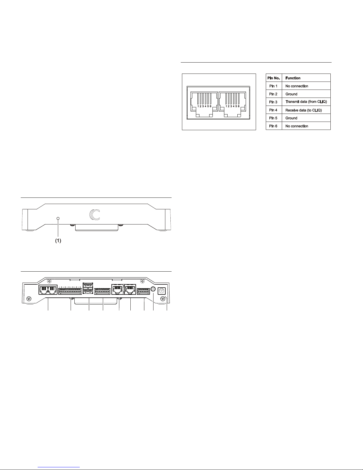
Figure 1: CLIQ.host front
(1) LED – Illuminates when unit is powered on
Figure 2: CLIQ.host rear connections
(1) RS-232 (2 ports)
(2) IR Outputs
(3) USB ports
(4) I/O
(5) CobraNet
(6) Ethernet
(7) Relay
(8) Z-Wave antenna
(9) Power – 12 VDC
RS-232 port pinouts
If you are using your own RJ12 cable (rather than the one
supplied), ensure your RJ12 cable connector pinouts match
the pinouts on the RS-232 ports, as shown in Figure 3.
Figure 3: RS-232 ports with pinouts
Powering the CLIQ.host
Plugging in the power adapter automatically turns on the
CLIQ.host and starts the boot process.
To connect power to the CLIQ.host:
1. Plug one end of the power adapter into a power receptacle
on the back of the CLIQ.host labeled “12vdc.” See
Figure 2, item 9.
2. Check the LED on the front of the CLIQ.host. It illuminates
blue when the device is receiving power. See Figure 1,
item 1.
Time, date, and time zone
Your CLIQ.host controller automatically detects and sets its
time, date, and time zone when you connect it to your data
network. CLIQ.host uses NTP and synchronizes the date and
time at boot up and periodically throughout the day.
Configure, test, and deploy a project
Refer to the Fusion Configuration Tool Administrator Guide
(Doc ID 069) for instructions on creating, testing, and deploying
a project. When you deploy the project from Fusion, it will
deploy to the CLIQ.host.
Adding the rubber foot covers
To prevent the unit from sliding, use the four rubber foot covers
included with your CLIQ.host.
To add the rubber foot covers:
• Peel each foot cover from the paper backing and place
one on each foot on the bottom of the CLIQ.host.
RS232
IR Outputs
USB
I/O
CobraNet Ethernet
Relay
#1 #2
12vdc
Networks
#1 #2
1 2 3 456
12vdc
Gnd
#3 #1#2
12vdc
Gnd
#4
NC
NO
C
NC
NO
C
(1)
(2)
(3) (4)
(5) (6)
(7)
(8)
(9)
RS232
#1 #2
 Loading...