

Clare Controls ClareVision Installation Manual
ClareVision
Network Video Record
Installation Guide
4
Doc ID 2015-01-344 • Rev 04
er
-Channel NVR with PoE

2 ClareVision Network Video Recorder Installation Guide
Copyright
© 13JAN15 Clare Controls, Inc. All rights reserved.
This document may not be copied in whole or in part or otherwise
reproduced without prior written consent from Clare Controls, Inc.,
except where specifically permitted under US and international
copyright law.
Trademarks
The ClareVision name is a trademark of Clare Controls, Inc.
Other trade names used in this document may be trademarks or
registered trademarks of the ma nu fa ctu re rs o r ve n do rs of the
respective products.
Version
This document applies to CV-B4410-01 ClareVision Network Video
Recorder Installation Guide Revision 01.
Contact information
For contact information, see www.clarecontrols.com.
Note: The figures shown in this manual are for reference only. The appearance
and interface of the device are subject to the actual model.

ClareVision Network Video Recorder Installation Guide i
Content
NVR pre-installation...1!
Package contents...1!
NVR installation...1!
Hard disk installation (optional)...2!
Front panel...4!
Rear panel...5!
HDD storage calculation chart...6!
Startup...7!
Using the Setup Wizard...7!
Live View...11!
Adding and configuring IP cameras...11!
Configuring basic parameters of IP cameras...12!
PTZ control...14!
PTZ settings...14!
PTZ control...15!
Playback...16!
Instant playback by channel...16!
Playback by channel...16!
Backup...17!
Understanding camera capacity in an NVR...19!
Streaming video types...19!
Adjusting settings...20!
Specifications...21!
Regulatory information...22!
Contact information...23!

ii ClareVision Network Video Recorder Installation Guide

ClareVision Network Video Recorder Installation Guide 1
NVR pre-installation
This NVR is highly advanced surveillance equipment that should be installed with
care. Follow these precautionary steps before the installation of the NVR.
• Keep all liquids away from the NVR.
• Install the NVR in a well-ventilated and dust-free area.
• Ensure environmental conditions meet factory specifications.
• Install a manufacturer recommended HDD.
Package contents
1 X 4 channel NVR appliance
1 X AC power cord
1 X optical mouse
1 X remote Control
1 X SATA hard drive cable
4 X small Phillips head screws
1 X technical bulletin: NVR Understanding Camera Capacity
NVR installation
When installing the NVR:
• Ensure there is ample room for the audio and video cables.
• When routing cables, ensure that the bend radius of the cables is no less than
five times the diameter.
• Connect both the alarm and RS-485 cable.
• Ensure the NVR is grounded.
• Environmental temperature should be within the range of 14ºF to 131ºF
(-10
ºC to 55 ºC).
• Environmental humidity should be within the range of 10% to 90%.
2 ClareVision Network Video Recorder Installation Guide
Hard disk installation (optional)
Additional SATA hard disks can be installed on your NVR. Disconnect the power
from the NVR before installing a hard disk drive (HDD). A factory recommended
HDD should be used for this installation.
Tools required: screwdriver.
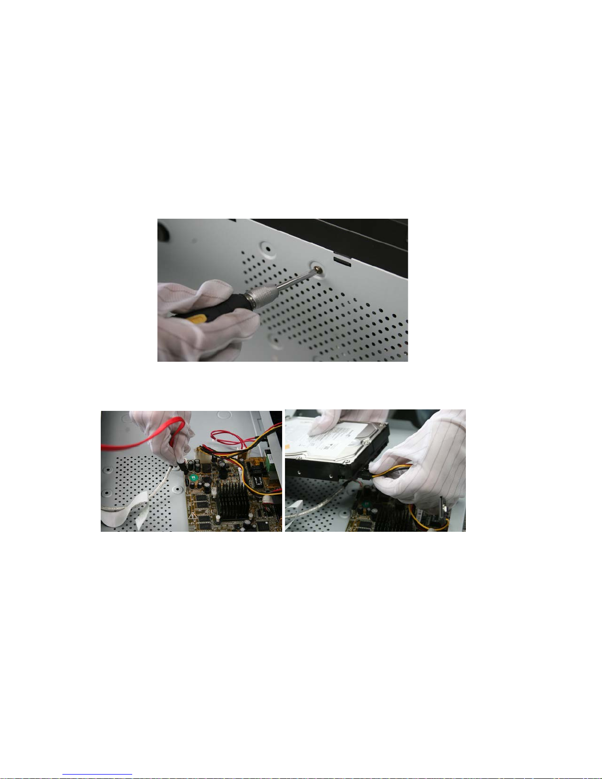
To install the hard disk drive into the NVR:
1. Remove the cover from the NVR by unfastening the screws on the rear and
side panels.
2. Connect one end of the data cable to the motherboard of the NVR and the
other end to the HDD.
ClareVision Network Video Recorder Installation Guide 3
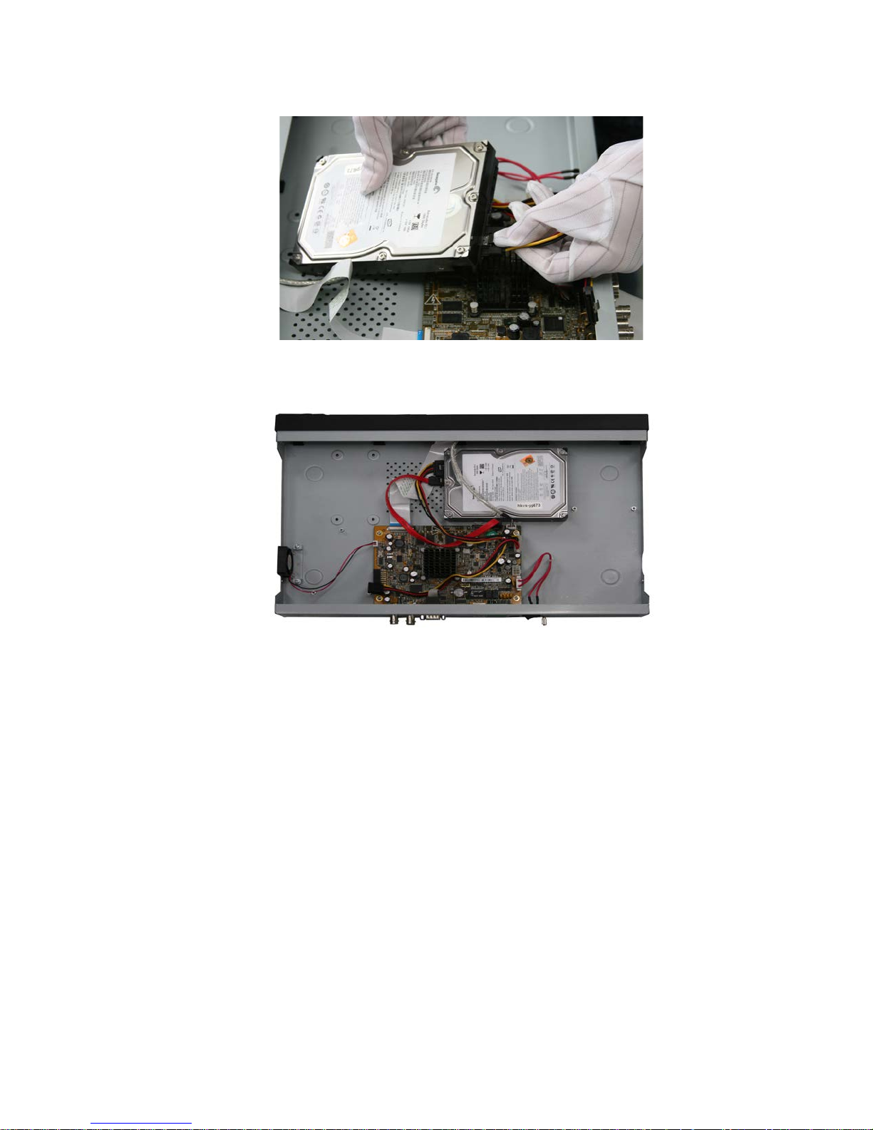
3. Connect the power cable to the HDD.
4. Place the HDD on the bottom of the device, and then fasten the screws on
the bottom to affix the HDD.
4 ClareVision Network Video Recorder Installation Guide
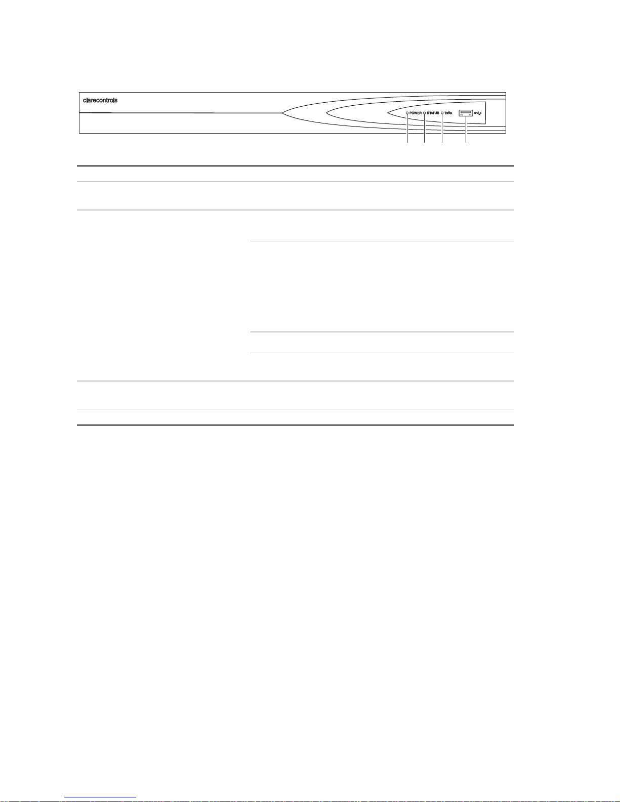
Front panel
No.
Name
Description
1
Power
POWER: The POWER LED turns green when the NVR
is powered up.
2
Status
READY: The LED is green when the device is running
normally.
STATUS:
1. The light is green when the IR remote control is
enabled.
2. The light is red when the functio n o f th e composite
keys (SHIFT) are used.
3. The light will not be on if one of the above conditions
are not met.
ALARM: When an alarm occurs, the light will turn red.
HDD: The LED flashes red when the HDD is
reading/writing.
3
Tx/Rx
Tx/Rx LED flashes green when the network connection
is functioning normally.
4
USB
USB connector.
(1) (2) (3) (4)
ClareVision Network Video Recorder Installation Guide 5
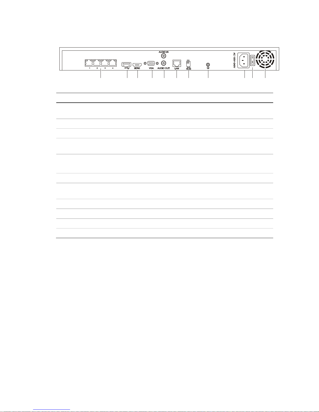
Rear panel
No.
Item
Description
1
Network Interfaces with
PoE function
The network interfaces for the cameras and provide power
over Ethernet.
2
USB
Connects USB disks and devices.
3
HDMI
HDMI video output connector.
4
VGA
DB9 connector for VGA output. Display local video output
and menu.
5
AUDIO IN
BNC connector for audio input. (Also for two-way audio)
AUDIO OUT
BNC connector for audio output.
6
LAN Interface
1 network interface.
7
RS-485 Interface
Connector for RS-485 devices. T+ and T- pins connect to
R+ and R- pins of PTZ receiver respectively.
8
Ground
Ground (needs to be connected when NVR starts up).
9
Power Supply
12 VDC power supply.
10
Power Switch
Switch for turning on/off the device.
11
Fan
Removes heat from the device.
(1) (2) (3) (4) (5) (6) (7)
(8) (9) (10)
(11)
 Loading...