

Clare Controls 4-Channel NVR with PoE, 8-Channel NVR with PoE, 16-Channel NVR with PoE, 32-Channel NVR with PoE, 64-Channel NVR with PoE User Manual

Network Video Recorder
User Manual
Models
4-Channel NVR with PoE
8-Channel NVR with PoE
16-Channel NVR with PoE
32-Channel NVR with PoE
64-Channel NVR with PoE
DOC ID 2014-12-371 • Rev 05

Copyright
© 29DEC14 Clare Controls, Inc. All rights reserved.
This document may not be copied in whole or in part or otherwise
reproduced without prior written consent from Clare Controls, Inc.,
except where specifically permitted under US and international
copyright law.
Trademarks and
patents
The Clare Controls Network Video Recorder User Manual name and
logo are trademarks of Clare Controls, Inc.
Other trade names used in this document may be trademarks or
registered trademarks of the manufacturers or vendors of the
respective products.
Manufacturer
Clare Controls, Inc.
7519 Pennsylvania Ave., Suite 104, Sarasota, FL 34243, USA
Contact information
Clare Controls, Inc.
7519 Pennsylvania Ave, Suite 104
Sarasota, FL 34243
Support: 941.404.1072
Fax: 941.870.9646
http://support.clarecontrols.com
www.clarecontrols.com


Content
Important information ............................................................................ v
Limitation of liability .............................................................................. v
Advisory messages .............................................................................. v
Chapter 1 Introduction ....................................................................................... 1
Introduction ........................................................................................... 1
Front panel ........................................................................................... 1
IR remote control operations ................................................................ 6
Troubleshooting the remote control ........................................... 8
USB mouse operation .......................................................................... 8
The mouse operation ................................................................. 9
Input method description ...................................................................... 9
Rear panel .......................................................................................... 10
Chapter 2 Getting Started ................................................................................ 14
Starting up and shutting down the NVR .............................................. 14
Shutting down the NVR ........................................................... 15
Rebooting the NVR .................................................................. 16
Using the wizard for basic configuration ............................................. 16
Adding and connecting the IP cameras .............................................. 22
Adding the online IP cameras ............................................................. 22
Editing the connected IP cameras and configuring customized
protocols ............................................................................................. 25
Configuring the customized protocols ................................................. 26
Editing IP cameras connected to the PoE interfaces ............... 28
Chapter 3 Introduction to Live View ............................................................... 30
Introduction to Live View .................................................................... 30
Operations in Live View mode ............................................................ 30
Front panel operation in Live View ........................................... 31
Using the mouse in Live View .................................................. 32
Using an auxiliary monitor ....................................................... 33
Quick Setting toolbar in Live View mode ................................. 34
Adjusting Live View settings ............................................................... 36
Setting cameras order ............................................................. 37
Channel-zero encoding ...................................................................... 37
User logout ......................................................................................... 38
Network Video Recorder User Manual i

Chapter 4 Configuring PTZ Settings ............................................................... 39
Configuring PTZ settings .................................................................... 39
Setting PTZ presets, patrols, and patterns ......................................... 40
Customizing presets ................................................................ 40
Calling presets ......................................................................... 41
Customizing patrols ................................................................. 42
Calling patrols .......................................................................... 43
Customizing patterns ............................................................... 44
Calling patterns ....................................................................... 45
PTZ control panel ............................................................................... 46
Chapter 5 Record and Capture Settings ........................................................ 47
Configuring parameters ...................................................................... 47
Configuring record/capture schedule ................................................. 50
Configuring motion detection record and capture ............................... 54
Configuring alarm triggered record and capture ................................. 56
Manual record and continuous capture .............................................. 58
Configuring holiday record and capture ............................................. 59
Configuring redundant recording and capture .................................... 60
Configuring HDD group for recording and capture ............................. 62
Files protection ................................................................................... 63
Playing back record files .................................................................... 65
Playing back by channel .......................................................... 65
Playing back by time ................................................................ 67
Playing back by event search .................................................. 69
Playing back by tag ................................................................. 73
Playing back by system logs ................................................... 77
Playing back external file ......................................................... 78
Auxiliary functions of playback ........................................................... 79
Playing back frame by frame ................................................... 79
Smart search ........................................................................... 80
Digital zoom ............................................................................. 83
Reverse playback of multi-channel .......................................... 83
Picture playback ................................................................................. 84
Backing up recorded files ................................................................... 86
Backing up by normal video search ................................................... 86
Backing up by event search ............................................................... 93
Backing up video clips ........................................................................ 95
Backing up pictures ............................................................................ 97
Managing backup devices .................................................................. 99
Chapter 8 Alarm Settings .............................................................................. 102
Setting motion detection alarm ......................................................... 102
Setting sensor alarms ...................................................................... 104
Detecting video loss alarm ............................................................... 106
Detecting video tampering alarm ...................................................... 107
Handling alarm exceptions ............................................................... 109
Setting alarm response actions ........................................................ 110
ii Network Video Recorder User Manual

Full screen monitoring ...................................................................... 110
Audible warning ................................................................................ 110
Notify surveillance center ................................................................. 110
Email linkage .................................................................................... 111
Trigger alarm output ......................................................................... 111
Triggering or clearing alarm output manually ................................... 112
Chapter 9 Network Settings ........................................................................... 114
Configuring general settings ............................................................. 114
Configuring advanced settings ......................................................... 116
Configuring PPPoE settings ............................................................. 116
Configuring DDNS ............................................................................ 116
ClareVision DDNS: ................................................................ 117
IPServer: ................................................................................ 117
DynDNS: ................................................................................ 117
PeanutHull: ............................................................................ 118
NO-IP: .................................................................................... 118
Configuring NTP server .................................................................... 118
Configuring SNMP ............................................................................ 119
Configuring a remote alarm host ...................................................... 120
Configuring multicast ........................................................................ 120
Configuring RTSP............................................................................. 121
Configuring server and HTTP ports .................................................. 122
Configuring a HTTPS port ................................................................ 122
Configuring Advanced ...................................................................... 123
Configuring email.............................................................................. 124
Configuring high-speed downloads .................................................. 126
Checking network traffic ................................................................... 127
Configuring network detection .......................................................... 127
Testing network delay and packet loss ............................................. 127
Exporting network packets ............................................................... 128
Checking the network status ............................................................ 129
Checking network statistics .............................................................. 130
Chapter 10 RAID ............................................................................................. 131
Configuring array and virtual disk ..................................................... 131
Introduction ....................................................................................... 131
One-touch configuration ................................................................... 132
Manually creating array and virtual disk ........................................... 134
Rebuilding array ............................................................................... 139
Automatically rebuilding array .......................................................... 139
Manually rebuilding array ................................................................. 140
Repairing a virtual disk ..................................................................... 141
Deleting the virtual disk and array .................................................... 142
Deleting the virtual disk .................................................................... 142
Deleting the array ............................................................................. 143
Migrating and extending ................................................................... 143
Upgrading firmware .......................................................................... 147
Network Video Recorder User Manual iii

Initializing HDDs ............................................................................... 149
Managing Network HDD................................................................... 150
Managing eSATA ............................................................................. 152
Managing the HDD group................................................................. 153
Setting HDD groups ............................................................... 153
Setting the HDD property ...................................................... 155
Configuring Quota mode .................................................................. 156
Checking HDD status ....................................................................... 157
HDD detection .................................................................................. 158
Configuring HDD error alarms .......................................................... 159
Chapter 12 Camera Settings ......................................................................... 161
Configuring OSD settings ................................................................. 161
Configuring privacy mask ................................................................. 162
Configuring video parameters .......................................................... 163
Chapter 13 NVR Management and Maintenance ......................................... 164
Viewing system information .............................................................. 164
Searching and export log files .......................................................... 166
Importing and exporting configuration files ....................................... 169
Upgrading the system ...................................................................... 170
Restoring default settings ................................................................. 172
Chapter 14 Other Settings ............................................................................. 173
Understanding camera capacity in an NVR...................................... 173
Streaming video types ........................................................... 173
Adjusting settings .................................................................. 174
Configuring RS-232 serial ports ....................................................... 174
Configuring general settings ............................................................. 175
Configuring DST settings ................................................................. 176
Configuring more settings for device parameters ............................. 176
Adding a camera using the web interface ........................................ 177
Managing user accounts .................................................................. 178
Adding a user ........................................................................ 179
Deleting a user ...................................................................... 182
Editing a user ........................................................................ 182
Appendix A Troubleshooting ........................................................................ 185
Glossary .......................................................................................................... 194
iv Network Video Recorder User Manual

Important information
Limitation of liability
To the maximum extent permitted by applicable law, in no event will Clare
Controls, Inc. be liable for any lost profits or business opportunities, loss of use,
business interruption, loss of data, or any other indirect, special, incidental, or
consequential damages under any theory of liability, whether based in contract,
tort, negligence, product liability, or otherwise. Because some jurisdictions do not
allow the exclusion or limitation of liability for consequential or incidental
damages the preceding limitation may not apply to you. In any event the total
liability of Clare Controls, Inc. shall not exceed the purchase price of the product.
The foregoing limitation will apply to the maximum extent permitted by applicable
law, regardless of whether Clare Controls, Inc. has been advised of the
possibility of such damages and regardless of whether any remedy fails of its
essential purpose.
Installation in accordance with this manual, applicable codes, and the instructions
of the authority having jurisdiction is mandatory.
While every precaution has been taken during the preparation of this manual to
ensure the accuracy of its contents, Clare Controls, Inc. assumes no
responsibility for errors or omissions.
Advisory messages
Advisory messages alert you to conditions or practices that can cause unwanted
results. The advisory message used in this document is shown and described
below.
Note: Note messages advise you of the possible loss of time or effort. They
describe how to avoid the loss. Notes are also used to point out important
information that you should read.
Network Video Recorder User Manual v

No.
Name
Description
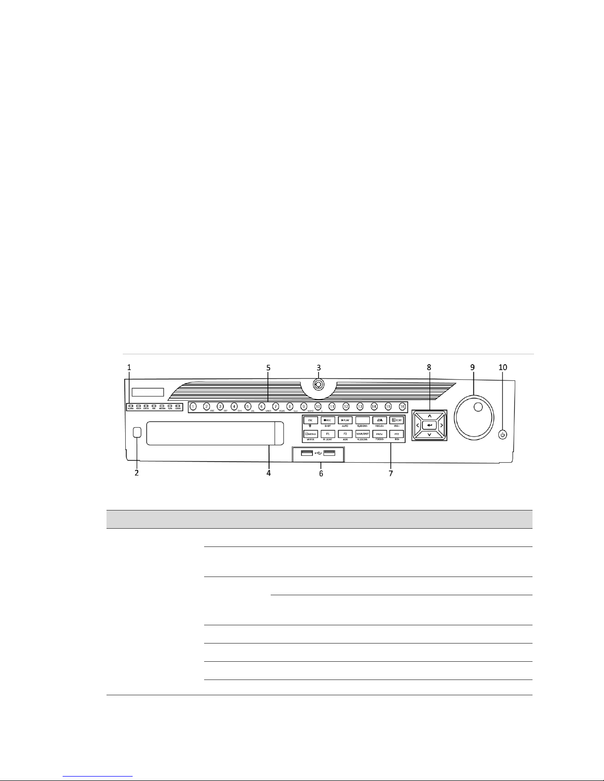
1
Status Indicators
ALARM
Turns red when a sensor alarm is detected.
READY
Ready indicator is normally blue, indicating that the device is
functioning properly.
STATUS
Turns blue when an IR remote controls the device.
Turns red when controlled by a keyboard and purple when the
IR remote and keyboard is used at the same time.
HDD
Blinks red when data is being read from or written to HDD.
MODEM
Reserved for future usage.
TX/RX
Blinks blue when the network connection is functioning properly.
Guard indicator turns blue when the device is in armed status. At
Chapter 1
Introduction
Introduction
Front panel
Figure 1: 64-Channel NVR front panel
Table 1: 64-Channel NVR control panel buttons
Network Video Recorder User Manual 1

Chapter 1: Introduction
GUARD
this time, an alarm is enabled when an event is detected.
The indicator turns off when the device is unarmed. Pressing
and holding the ESC button for more than three seconds in Live
View mode can change the arm/disarm status.
2
IR Receiver
Receiver for IR remote.
3
Front Panel Lock
You can lock or unlock the panel by the key.
4
DVD-R/W
Slot for DVD-R/W.
5
Alphanumeric Buttons
Switch to the corresponding channel in Live view or PTZ Control
mode.
Switch between different channels in Playback mode.
The light of the button is blue when the corresponding channel is
recording; it is red when the channel is in network transmission
status; it is pink when the channel is recording and transmitting.
6
USB Interfaces
Universal Serial Bus (USB) ports for additional devices such as
USB mouse and USB Hard Disk Drive (HDD).
7
Composite Keys
ESC
Back to the previous menu.
Press for arming or disarming the device in Live View mode.
REC/SHOT
Enter the Manual Record setting menu.
In PTZ control settings, press the button and then you can call a
PTZ preset by pressing Numeric button.
It is also used to turn audio on and off in the Playback mode.
PLAY/AUTO
The button is used to enter the Playback mode.
It is also used to auto-scan in the PTZ Control menu.
ZOOM+
Zoom in the PTZ camera in the PTZ Control setting.
A/FOCUS+
Adjust focus in the PTZ Control menu.
It is also used to switch between input methods (upper and
lowercase alphabet, symbols and numeric input).
EDIT/IRIS+
Edit text fields. When editing text fields, it will also function as a
Backspace button to delete the character in front of the cursor.
On checkbox fields, pressing the button will tick the checkbox.
In PTZ Control mode, the button adjusts the iris of the camera.
In Playback mode, it can be used to generate video clips for
backup.
Enter or exit the folder of USB device and eSATA HDD.
MAIN/SPOT/
ZOOM-
Switch between main and spot output.
In PTZ Control mode, it can be used to zoom out the image.
F1/LIGHT
Select all items on the list when used in a list field.
In PTZ Control mode, it will turn on/off PTZ light (if applicable).
2 Network Video Recorder User Manual

Chapter 1: Introduction
In Playback mode, it is used to switch between play and reverse
play.
F2/AUX
Cycle through tab pages.
In synchronous playback mode, it is used to switch between
channels.
MENU/WIPER
Press the button will help you return to the Main menu (after
successful login).
Press and hold the button for 5 seconds will turn off audible key
beep.
In PTZ Control mode, the MENU/WIPER button will start wiper
(if applicable).
In Playback mode, it is used to show/hide the control interface.
PREV/FOCUS-
Switch between single screen and multi-screen mode.
In PTZ Control mode, it is used to adjust the focus in conjunction
with the A/FOCUS+ button.
PTZ/IRIS-
Enter the PTZ Control mode.
In the PTZ Control mode, it is used to adjust the iris of the PTZ
camera.
8
Control Buttons
DIRECTION
The DIRECTION buttons are used to navigate between different
fields and items in menus.
In the Playback mode, the Up and Down button is used to speed
up and slow down recorded video. The Left and Right button will
select the next and previous record files.
In Live View mode, these buttons can be used to cycle through
channels.
In PTZ control mode, it can control the movement of the PTZ
camera.
ENTER
The ENTER button is used to confirm selection in any of the
menu modes.
It can also be used to tick checkbox fields.
In Playback mode, it can be used to play or pause the video.
In single-frame Playback mode, pressing the button will advance
the video by a single frame.
In Auto-switch mode, it can be used to stop /start auto switch.
9
JOG SHUTTLE Control
Move the active selection in a menu. It will move the selection up
and down.
In Live View mode, it can be used to cycle through different
channels.
In the Playback mode: For 64-Channel NVRs, the ring is used
to jump 30s forward/backward in video files.
In PTZ control mode, it can control the movement of the PTZ
Network Video Recorder User Manual 3
Chapter 1: Introduction
No.
Name
Description
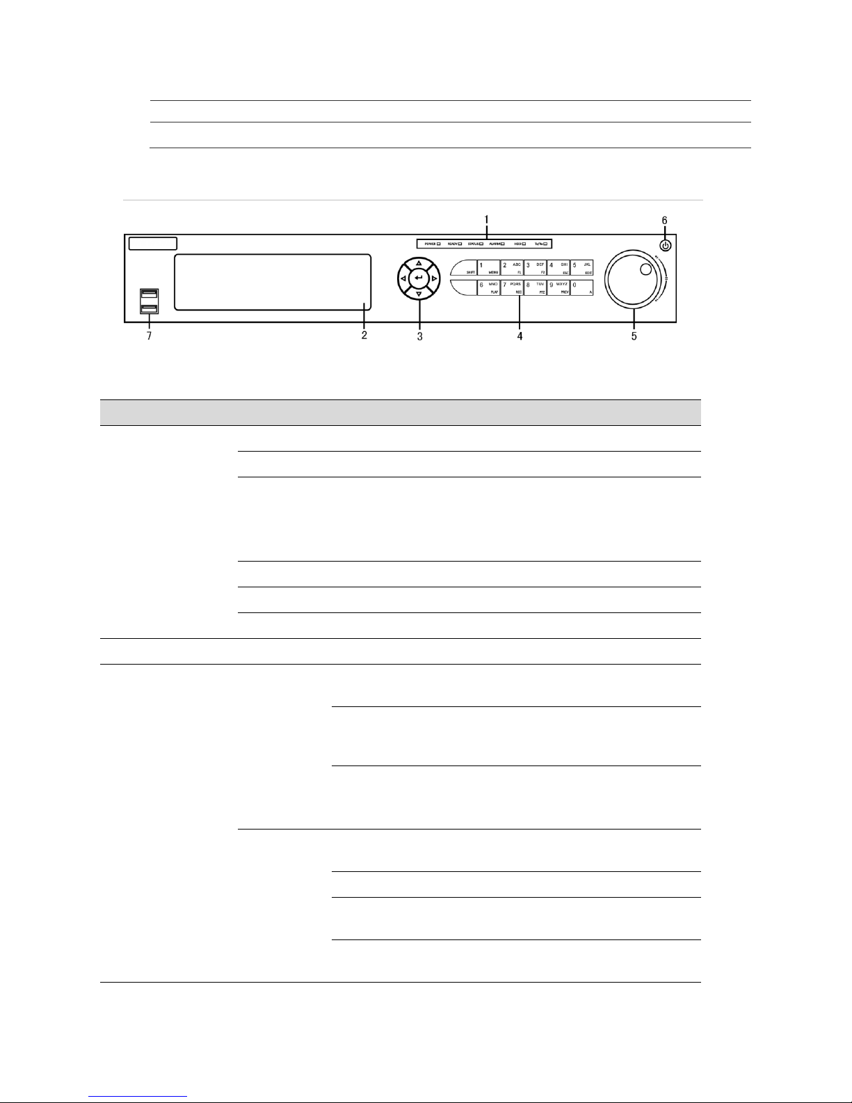
1
Status Indicators
POWER
Turns green when NVR is powered up.
READY
The indicator is green when the device is running normally.
STATUS
The light is green when the IR remote control is enabled;
The light is red when the function of the composite keys (SHIFT)
are used;
The light is out when none of the above condition is met.
ALARM
The light is red when there is an alarm occurring.
HDD
Blinks red when HDD is reading/writing.
Tr/Tx
Blinks green when network connection is functioning normally.
2
DVD-R/W
Slot for DVD-R/W.
3
Control Buttons
DIRECTIONS
In menu mode, the direction buttons are used to navigate
between different fields and items and select setting parameters.
In playback mode, the Up and Down buttons are used to speed
up and slow down record playing. The Left and Right buttons are
used to move the recording 30 seconds forwards or backwards.
In the image setting interface, the up and down button can adjust
the level bar of the image parameters.
In live view mode, these buttons can be used to switch channels.
ENTER
The Enter button is used to confirm selection in menu mode; or
used to check checkbox fields and ON/OFF switch.
In playback mode, it can be used to play or pause the video.
In single-frame play mode, pressing the Enter button will play the
video by a single frame.
In auto sequence view mode, the buttons can be used to pause
or resume auto sequence.
camera.
10
POWER ON/OFF
Power on/off switch.
Figure 2: 16-Channel NVR and 32-Channel NVR front panel
Table 2: 16-Channel NVR and 32-Channel NVR control panel buttons
4 Network Video Recorder User Manual

Chapter 1: Introduction
4
Composite Keys
SHIFT
Switch between the numeric or letter input and functions of the
composite keys. (Input letter or numbers when the light is out;
Realize functions when the light is red.)
1/MENU
Access the main menu interface.
2/ABC/F1
The F1 button when used in a list field will select all items in the
list.
In PTZ Control mode, it will turn on/off PTZ light and when the
image is zoomed in, the key is used to zoom out.
3/DEF/F2
The F2 button is used to change the tab pages.
In PTZ control mode, it zooms in the image.
4/FHI/ESC
Exit and back to the previous menu.
5/JKL/EDIT
Delete characters before cursor.
Check the checkbox and select the ON/OFF switch.
Start/stop record clipping in playback.
6/MNO/PLAY
Playback, for direct access to playback interface.
7/PQRS/REC
Open the manual record interface.
8/TUV/PTZ
Access PTZ control interface.
9/WXYZ/PREV
Multi-channel display in live view.
0/A
Shift the input methods in the editing text field. (Upper and
lowercase, alphabet, symbols or numeric input).
Double press the button to switch the main and auxiliary output.
5
JOG SHUTTLE Control
Move the active selection in a menu. It will move the selection up
and down.
In Live View mode, it can be used to cycle through different
channels.
In the Playback mode, it can be used to jump 30s
forward/backward in video files.
In PTZ control mode, it can control the movement of the PTZ
camera.
6
POWER ON/OFF
Power on/off switch.
7
USB Interfaces
Universal Serial Bus (USB) ports for additional devices such as
USB mouse and USB Hard Disk Drive (HDD).
Network Video Recorder User Manual 5

Chapter 1: Introduction
No.
Name
Description
1
Power
POWER: The POWER LED turns green when NVR is
powered up.
2
Status
READY: The LED is green when the device is running
normally.
STATUS: 1) The light is green when the IR remote
control is enabled. 2) The light is red when the function
of the composite keys (SHIFT) is used. 3) The light is
out when none of the above condition is met.
ALARM: The light is red when there is an alarm
occurring.
HDD: The LED flashes red when HDD is
reading/writing.
3
Tx/Rx
TX/RX LED flashes green when network connection is
functioning normally.
4
USB
USB connector
1 2 3
4
Figure 3: 4-Channel and 8-Channel NVR front panel
Table 3: 4-Channel and 8-Channel NVR control panel buttons
IR remote control operations
The NVR may also be controlled with the included IR remote control, shown
below. The keys on the remote control closely resemble the ones on the front
panel.
Note: Batteries (2 × AAA) must be installed before operation.
6 Network Video Recorder User Manual

Figure 4: Remote control
No.
Name
Description
1
POWER
Power on/off the device.
2
DEV
Enables/Disables Remote Control.
3
Alphanumeric buttons
Same as Alphanumeric buttons on front panel.
4
EDIT button
Same as EDIT/IRIS+ button on front panel.
5
A button
Same as A/FOCUS+ button on front panel.
6
REC button
Same as REC/SHOT button on front panel.
7
PLAY button
Same as the PLAY/AUTO button on front panel.
8
INFO button
Reserved.
9
VOIP/MON button
Same as the MAIN/SPOT/ZOOM- button on front panel.
10
MENU button
Same as the MENU/WIPER button on front panel.
11
PREV button
Same as the PREV/FOCUS- button on front panel.
12
DIRECTION/ENTER buttons
Same as the DIRECTION/ENTER buttons on front panel.
13
PTZ button
Same as the PTZ/IRIS- button on front panel.
14
ESC button
Same as the ESC button on front panel.
15
RESERVED
Reserved for future usage.
Chapter 1: Introduction
Table 4: Remote control buttons
Network Video Recorder User Manual 7

Chapter 1: Introduction
16
F1 button
Same as the F1/LIGHT button on front panel.
17
PTZ Control buttons
Buttons to adjust the iris, focus and zoom of a PTZ
camera.
18
F2 button
Same as the F2/AUX button on front panel.
Troubleshooting the remote control
Note: Make sure you have installed batteries properly in the remote control. Be
sure to aim the remote control at the IR receiver in the front panel.
If you press a button and do not receive a response, follow the procedures below
to troubleshoot.
To troubleshoot the remote control:
1. Go to Menu > Settings > General > More Settings using the front control
panel or the mouse.
2. Check and remember the NVR ID. The default ID number is 255. This ID
number is valid for all the IR remote controls.
3. Press the DEV button on the remote control.
4. Enter the NVR ID number from step 2.
5. Press ENTER on the remote.
If the Status indicator on the front panel turns blue, the remote control is
operating properly. If the Status indicator does not turn blue and there is still no
response from the remote, check the following:
Batteries are installed correctly and that the polarities of the batteries are not
reversed.
Batteries are fresh and charged.
IR receiver is not obstructed.
If the remote still is not functioning properly, change remotes and try again, or
contact your dealer.
USB mouse operation
A regular 3-button (Left/Right/Scroll-wheel) USB mouse can also be used with
this NVR.
To use a USB mouse:
1. Plug USB mouse into one of the USB interfaces on the front panel of the
NVR.
8 Network Video Recorder User Manual
Chapter 1: Introduction
Name
Action
Description
Left-click
Single-click
Live view: Select channel and show the quick set menu.
Menu: Select and enter.
Double-click
Live view: Switch between single-screen and multi-screen.
Click and drag
PTZ control: pan, tilt and zoom.
Video tampering, privacy mask and motion detection:
Select target area.
Digital zoom-in: Drag and select target area.
Live view: Drag channel/time bar.
Right-click
Single-click
Live view: Show menu.
Menu: Exit current menu to upper level menu.
Wheel- scroll
Scrolling up
Live view: Previous screen.
Menu: Previous item.
Scrolling down
Live view: Next screen.
Menu: Next item.
2. The mouse should be automatically detected. If in the rare case the mouse is
not detected, it is possible that the two devices are not compatible. Refer to
the recommended device list from your provider.
The mouse operation
Table 5: Mouse control
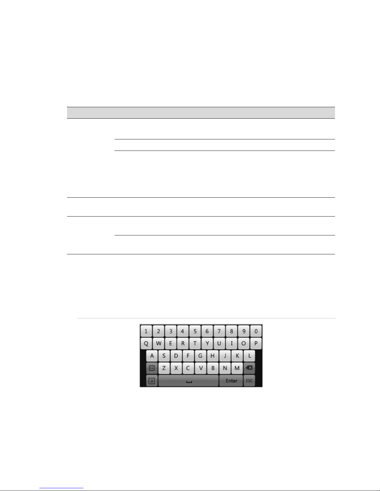
Input method description
You can use the soft keyboard to enter text. To display the keyboard, click the
123 icon.
Figure 5: Soft keyboard
Network Video Recorder User Manual 9
Chapter 1: Introduction
Icons
Description
Lowercase/uppercase
Space
Escape
Symbols
Backspace
Enter
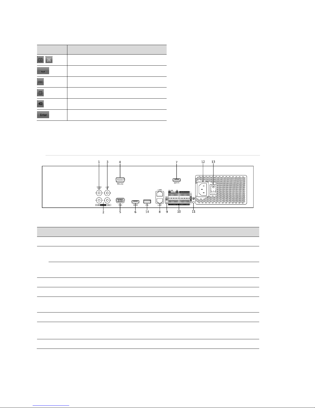
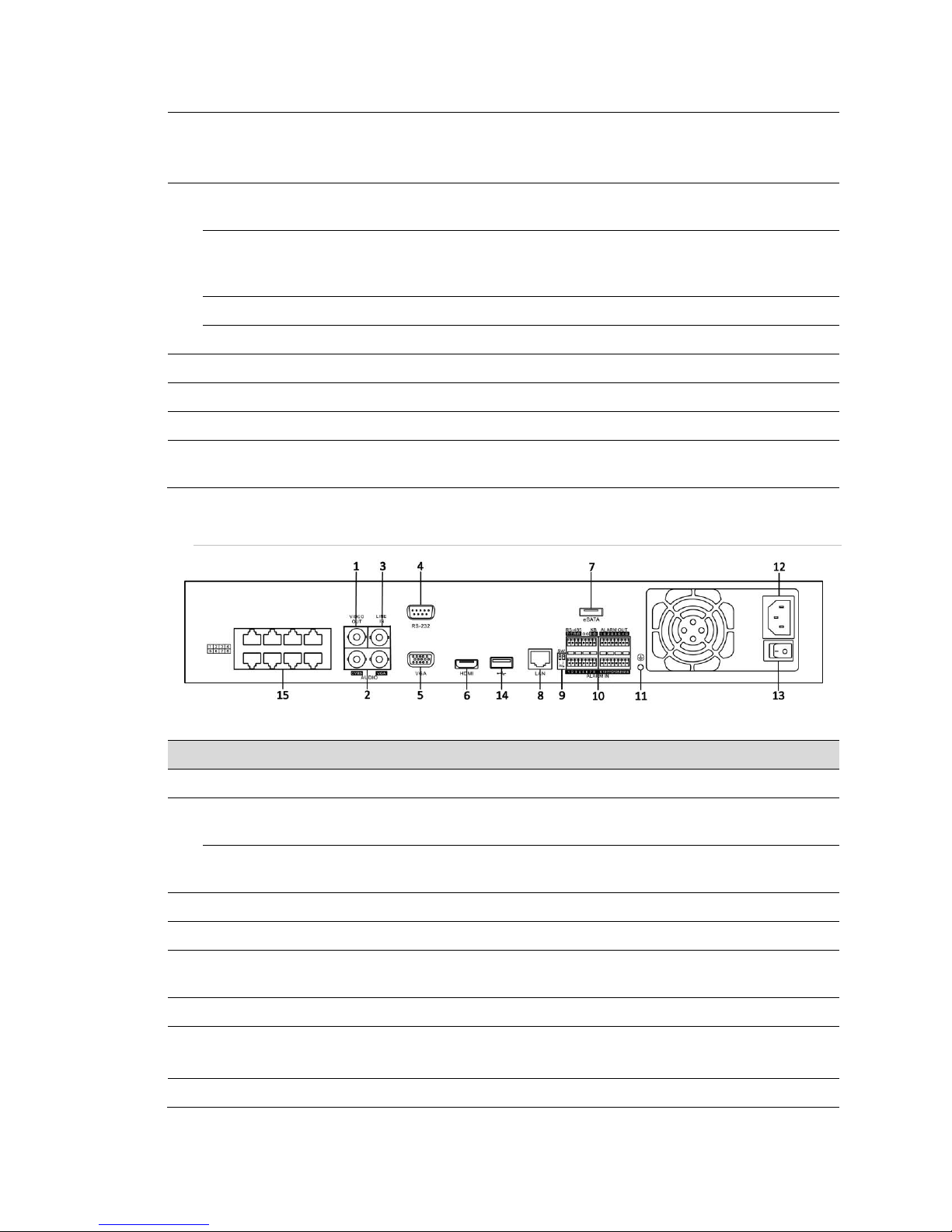
No.
Name
Description
1
VIDEO OUT
BNC connector for video output.
2
CVBS AUDIO OUT
BNC connector for audio output. This connector is
synchronized with CVBS video output.
VGA AUDIO OUT
BNC connector for audio output. This connector is
synchronized with VGA video output.
3
LINE IN
BNC connector for audio input.
4
RS-232 Interface
Connector for RS-232 devices.
5
VGA
DB9 connector for VGA output. Display local video output
and menu.
6
HDMI
HDMI video output connector.
7
eSATA (Optional)
Connects external SATA HDD, CD/DVD-RM.
2 eSATA interfaces.
8
LAN Interface
2 network interfaces.
Table 6: Soft keyboard icons
Rear panel
Figure 6: 64-Channel NVR rear panel
Table 7: 64-Channel NVR rear panel connections
10 Network Video Recorder User Manual
Chapter 1: Introduction
9
Termination Switch
RS-485 termination switch.
Up position is not terminated.
Down position is terminated with 120Ω resistance.
10
RS-485 Interface
Connector for RS-485 devices. T+ and T- pins connect to
R+ and R- pins of PTZ receiver respectively.
Controller Port
D+/D- pin connects to Ta, Tb pin of controller. For
cascading devices, the first NVR’s D+/D- pin should be
connected with the D+/D- pin of the next NVR.
ALARM IN
Connector for alarm input.
ALARM OUT
Connector for alarm output.
11
GROUND
Ground (needs to be connected when NVR starts up).
12
AC 100 to 240 V
AC 100 to 240 V power supply.
13
POWER
Switch for turning on/off the device.
14
USB interface
Universal Serial Bus (USB) ports for additional devices
such as USB mouse and USB Hard Disk Drive (HDD).
No.
Name
Description
1
VIDEO OUT
BNC connector for video output.
2
CVBS AUDIO OUT
BNC connector for audio output. This connector is
synchronized with CVBS video output.
VGA AUDIO OUT
BNC connector for audio output. This connector is
synchronized with VGA video output.
3
LINE IN
BNC connector for audio input.
4
RS-232 Interface
Connector for RS-232 devices.
5
VGA
DB9 connector for VGA output. Display local video output
and menu.
6
HDMI
HDMI video output connector.
7
eSATA (Optional)
Connects external SATA HDD, CD/DVD-RM.
2 eSATA interfaces.
8
LAN Interface
1 network interface provided.
Figure 7: CV-M16810-04 and CV-M32810-08 rear panel connections
Table 8: CV-M16810-04 and CV-M32810-08 rear panel connections
Network Video Recorder User Manual 11
Chapter 1: Introduction
9
Termination Switch
RS-485 termination switch.
Up position is not terminated.
Down position is terminated with 120 Ω resistance.
10
RS-485 Interface
Connector for RS-485 devices. T+ and T- pins connect to
R+ and R- pins of PTZ receiver respectively.
Controller Port
D+/D- pin connects to Ta, Tb pin of controller. For
cascading devices, the first NVR’s D+/D- pin should be
connected with the D+/D- pin of the next NVR.
ALARM IN
Connector for alarm input.
ALARM OUT
Connector for alarm output.
11
GROUND
Ground (needs to be connected when NVR starts up).
12
AC 100 to 240V
AC 100 to 240 V power supply.
13
POWER
Switch for turning on/off the device.
14
USB interface
Universal Serial Bus (USB) ports for additional devices
such as USB mouse and USB Hard Disk Drive (HDD).
15
Network Interfaces with PoE
function
Network interface for the cameras and to provide power
over Ethernet.
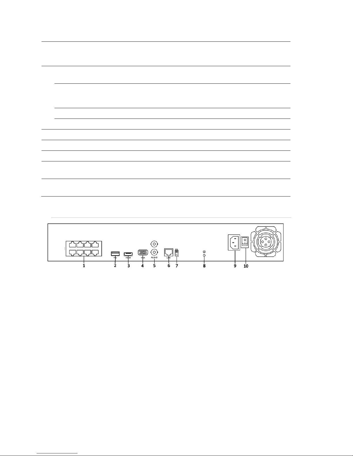
Figure 8: CV-B4410-01 and CV-B8810-02 rear panel
12 Network Video Recorder User Manual

Table 9: CV-B4410-01 and CV-B8810-02 rear panel connections
No.
Name
Description
1
Network Interfaces with
PoE function
Network interfaces for the cameras and to provide power over
Ethernet.
2
USB
Connects USB disks and devices.
3
HDMI
HDMI video output connector.
4
VGA
DB9 connector for VGA output. Display local video output and
menu.
5
AUDIO IN
BNC connector for audio input (also for two-way audio).
AUDIO OUT
BNC connector for audio output.
6
LAN Interface
1 network interface.
7
RS-485 Interface
Connector for RS-485 devices. T+ and T- pins connect to R+
and R- pins of PTZ receiver respectively.
8
Ground
Ground (needs to be connected when NVR starts up).
9
Power Supply
12 VDC power supply.
10
Power Switch
Switch for turning on/off the device.
Chapter 1: Introduction
Network Video Recorder User Manual 13

Chapter 2
Getting Started
Starting up and shutting down the NVR
Proper startup and shutdown procedures are crucial to expanding the life of the
NVR. Before you start, check that the voltage of the extra power supply is the
same with the NVR’s requirement, and that the ground connection is working
properly.
To start up the NVR:
1. Check the power supply is plugged into an electrical outlet. It is HIGHLY
recommended that an Uninterruptible Power Supply (UPS) be used in
conjunction with the device. The Power indicator LED on the front panel
should be red, indicating the device gets the power supply.
2. Press the POWER button on the front panel. The Power indicator LED should
turn blue indicating that the unit begins to start up.
3. After startup, the Power indicator LED remains blue. A splash screen with the
status of the HDD appears on the monitor. Clicking the Live View screen will
display the Quick menu. The Quick menu, a row of icons at the bottom of the
screen, shows the HDD status. ‘X’ means that the HDD is not installed or
cannot be detected.
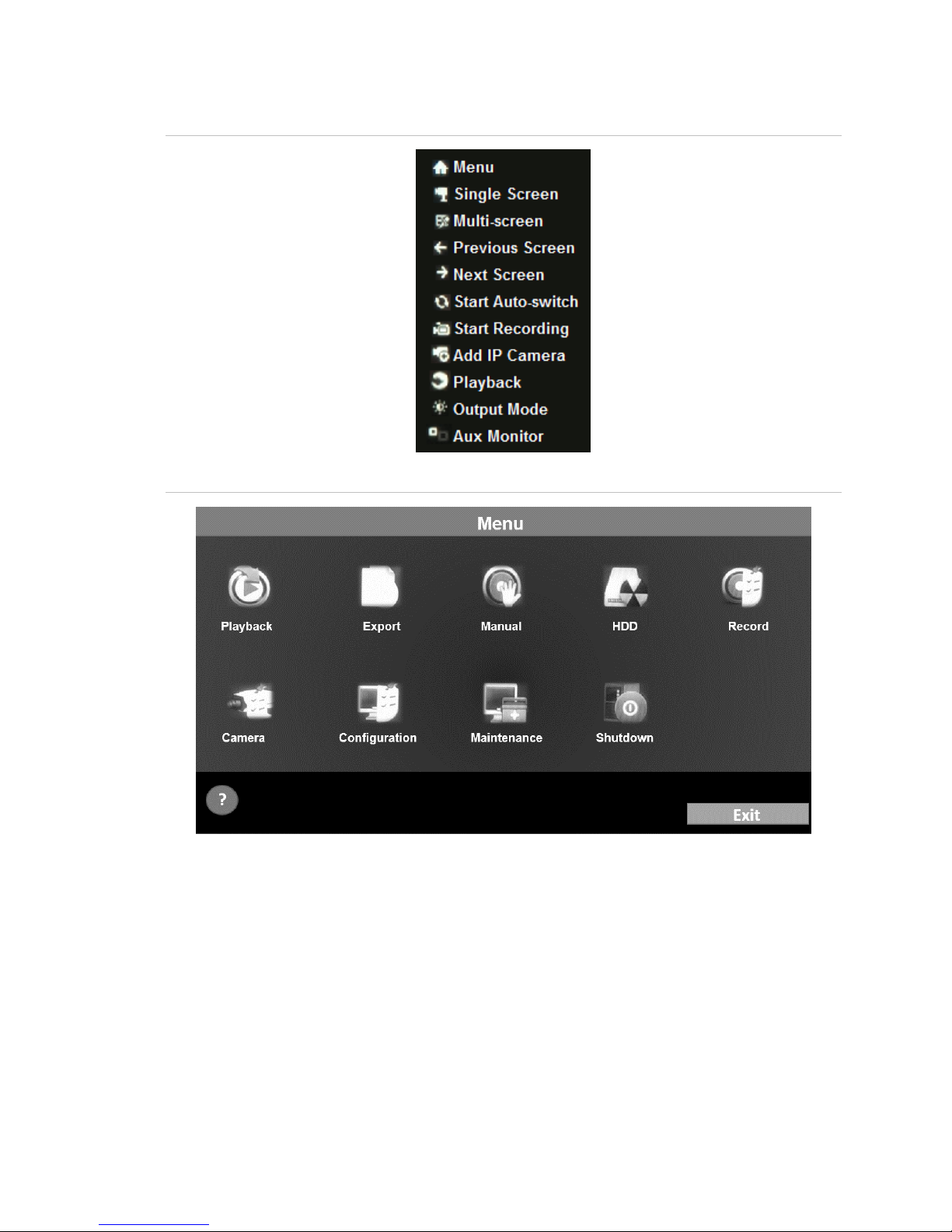
4. On the Live View screen, right click for a menu to appear, see figure 9 below.
Click Menu, on the top of the Right-click menu to display the Top menu, see
Figure 10 below. From the Top menu, you can configure advanced settings or
shutdown the NVR.
14 Network Video Recorder User Manual
Chapter 2: Getting Started
Figure 9: Right-click menu
Figure 10: Top menu
Shutting down the NVR
There are two proper ways to shut down the NVR.
To shut down the NVR (Option 1):
1. Click Menu > Shutdown. (See Figure 11.)
2. Click Shutdown.
3. Click Yes.
Network Video Recorder User Manual 15
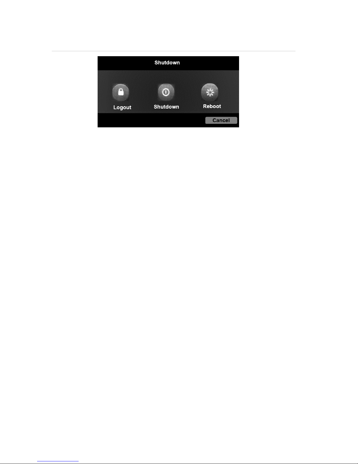
Chapter 2: Getting Started
Figure 11: Shutdown menu
To shut down the NVR from the front panel (Option 2):
1. Press and hold the POWER button on the front panel for three seconds.
2. Enter the administrator’s username and password in the dialog box for
authentication.
3. Click Yes.
Note: Do not press the POWER button again when the system is shutting down.
Rebooting the NVR
In the Shutdown menu, you can also reboot the NVR.
To reboot the NVR from the Shutdown menu:
1. Click Menu > Shutdown.
2. Click Reboot to reboot the NVR.
Using the wizard for basic configuration
By default, the Setup Wizard starts once the NVR has loaded, as shown in
Figure 12.
16 Network Video Recorder User Manual
Chapter 2: Getting Started
Figure 12: Start Wizard interface
To use the Setup Wizard:
1. The Setup Wizard can walk you through some important settings of the NVR.
If you don’t want to use the Setup Wizard, click the Cancel button. You can
also choose to use the Setup Wizard next time by selecting the “Start wizard
when the device starts?” checkbox.
2. Click Next on the Wizard window to enter the Login window, as shown in
Figure 13.
Figure 13: Login window
3. Enter the admin password. By default, the password is secure7.
4. To change the admin password, check the New Admin Password checkbox.
Enter the new password and confirm the password in the given fields.
Network Video Recorder User Manual 17
Chapter 2: Getting Started
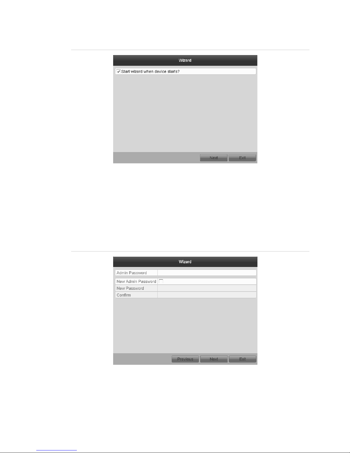
5. Click the Next button to enter the date and time settings window, as shown in
Figure 14.
Figure 14: Date and time settings
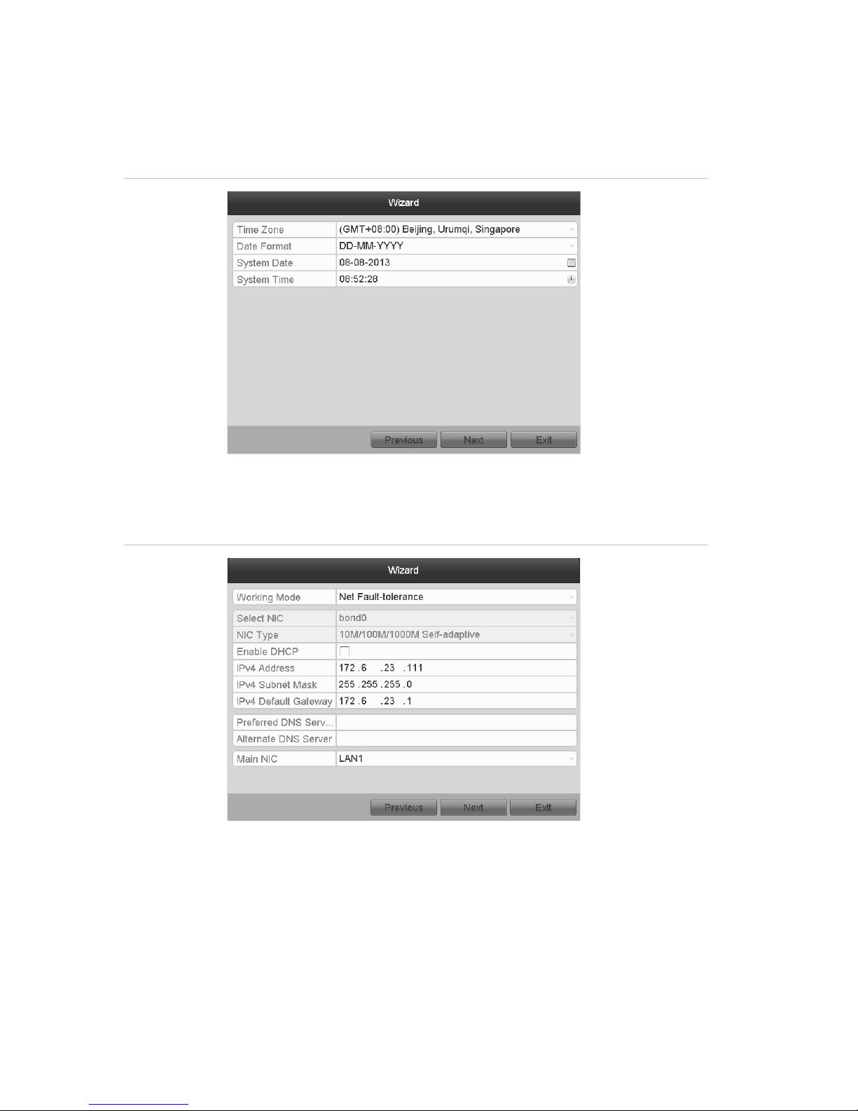
6. After the time settings, click Next. This returns you to the Network Setup
Wizard window, shown in Figures 15 and 16.
Figure 15: 64-Channel NVR network configuration
18 Network Video Recorder User Manual
Chapter 2: Getting Started
Figure 16: CV-B8810-02, CV-M16810-04, CV-M32810-08 network configuration
Note: Dual-NIC is only supported in the 64-Channel NVR device. For the
4-Channel NVR, 8-Channel NVR, 16-Channel NVR, and 32-Channel NVR
NVRs, configure the internal NIC IPv4 address for the cameras connecting to
the PoE network interface of the NVR.
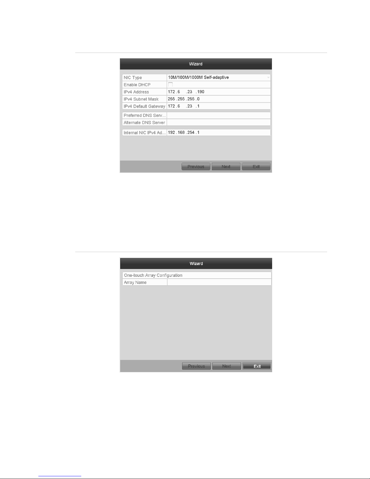
7. Configure the network parameters, and then click Next. It then takes you to
the Array Management window (supported by the 64-Channel NVR, only).
Figure 17: Array management
8. Configure the network parameters, and then click Next. This takes you to the
HDD Management window, shown in Figure 18.
Network Video Recorder User Manual 19
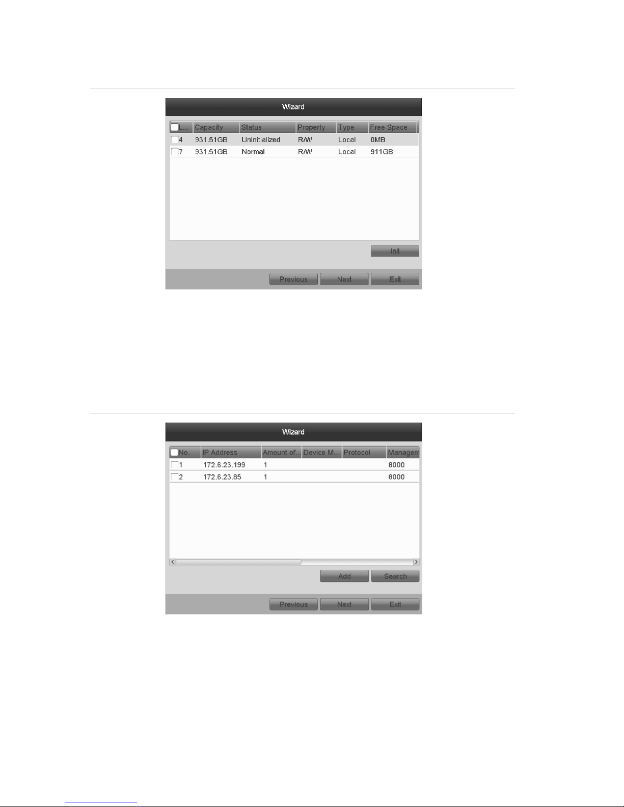
Chapter 2: Getting Started
Figure 18: HDD management
9. To initialize the HDD, click Init. Initialization removes all the data saved in the
HDD.
10. Click Next to enter the Adding IP Camera interface.
11. Click Search to find online IP Camera. Select the IP camera to be added, and
then click Add.
Figure 19: Search for IP cameras
12. Click Next. Configure the recording for the searched IP cameras.
20 Network Video Recorder User Manual
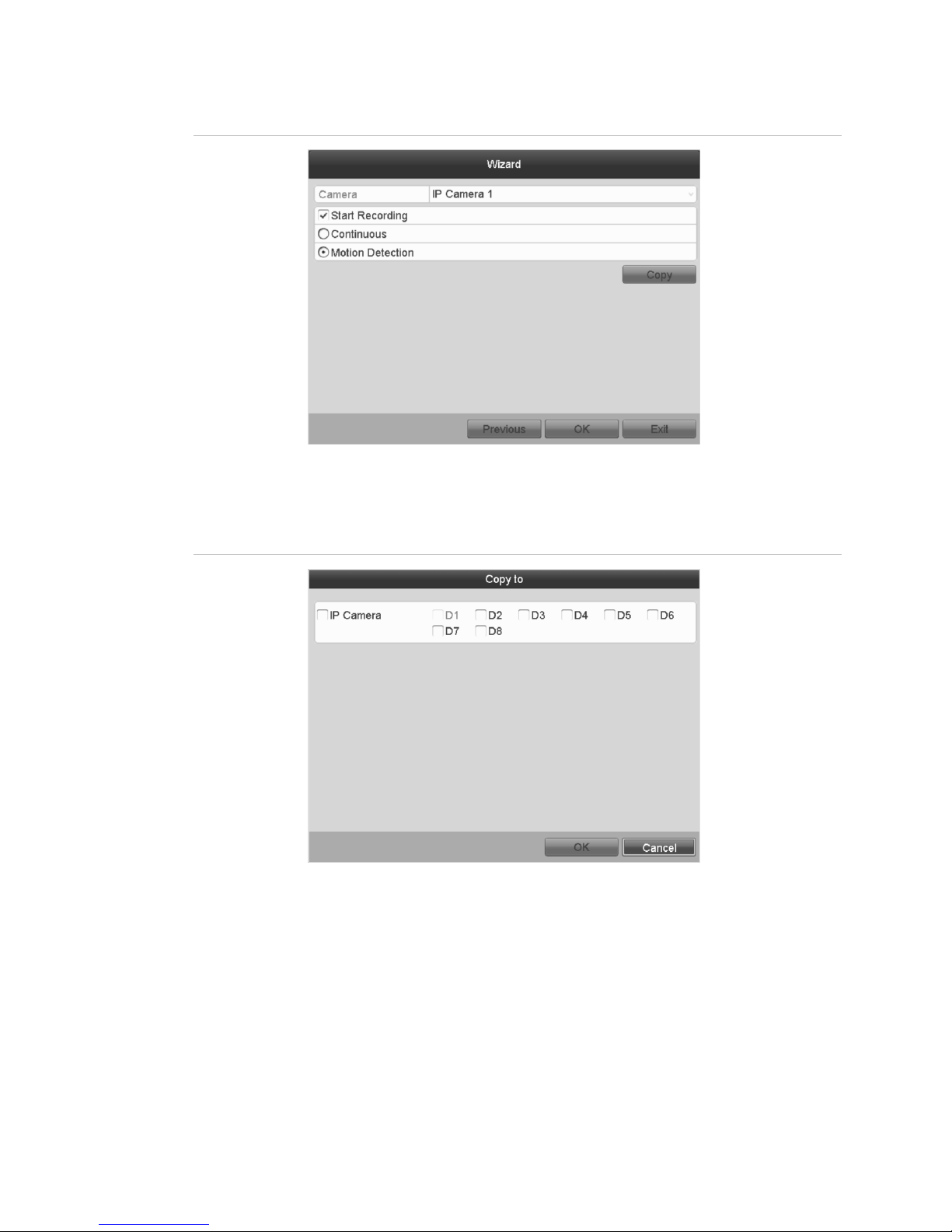
Chapter 2: Getting Started
Figure 20: Record settings
13. Click Copy to copy the settings to other channels, as shown in Figure 21.
Figure 21: Copy record settings
14. Click OK to complete the startup Setup Wizard.
Network Video Recorder User Manual 21
 Loading...