

Features Description
• Small size
• SMT-compatible
• Easily formed leads
• Sputtered ruthenium contacts
• Hermetically sealed contacts
• Fast switching speed — up to 500Hz
• Wide range of available magnetic sensitivities
Clare’s Mini-DYAD™ dry reed switches are ideally suited
for small switching signal applications. This switch has
sputtered ruthenium contacts and an extraordinary seal
strength, achieved by a patented laser sealing of the glass.
In low level or dry switching environments, both switches
typically provide >1 billion operations. The switches have
hermetically sealed contacts and offer a wide range of
available magnetic sensitivities.
Mini-Dyad
MN2
™
Applications
• Security
• Proximity sensing
• Smoke alarms
• Automotive
• Level sensor
• Lamp current sensor
• Relays
Approvals
• UL listed
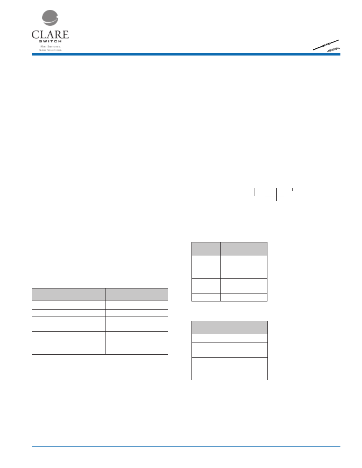
Standard Test Coil
The magnetic force (expressed in NI, AT or Ampere Turns) required to cause the reed switch contacts to
close is called the pull-in or operate value.
MN2
Part # Coil - 1
Coil definition NARM1 CTC01
Coil resistance 1200Ω
Number of turns 5,000
Wire size (nom. diameter) 0.0399mm (AWG 46)
Bobbin diameter (inside coil) 3.96mm
Winding length 10.4mm
(1)
Consult factory for test procedure.
The reed switch shall be placed in the test coil with the gap centered in the core of the coil winding.
Test leads and their clips must be non-magnetic.
The longitudinal axis of the test coil and the test switch shall be vertical.
Ordering Information
A complete part number is represented by the digits to the right. For example, MN2S1030 is a
MINI-DYAD™ with a minimum operate value of 10 and a maximum of 30. Refer to the switch
operating specification charts for available ranges. Special ranges are available upon request.
XX
1,2,3
X
Maximum Operate Value (NI)
Lead Configuration
1
Packaging
MN2S XX XX
Minimum Operate Value (NI)
Surface Mount Mini-Dyad
Refer to operating characteristics table for complete part number.
Mini-DYAD
TM
Part # Operate Range (NI)
MN2S1015 10 to 15
MN2S1020 10 to 20
MN2S1030 10 to 30
MN2S1520 15 to 20
MN2S1525 15 to 25
MN2S2025 20 to 25
Mini-DYAD
TM
Surface Mount
Part # Operate Range (NI)
MN2308 10 to 15
MN2288 10 to 20
MN2339 10 to 30
MN2285 15 to 20
MN2289 15 to 25
MN2286 20 to 25
1
Tolerance = ± 1.5NI
2
Full Blade Sensitivity
3
Surface Mount Switches are packaged 2,000 parts per reel
DS-MN2-R2
www.clare.com
1
Mini-Dyad
MN2
™
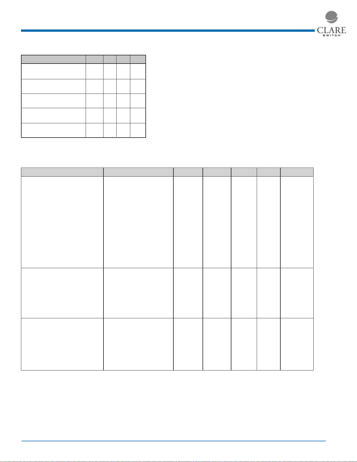
Ratings (@ 25˚ C)
Parameter Min Typ Max Units
Switching Voltage
MN2 - Mini-DYAD
Switching Current
MN2 - Mini-DYAD
Carry Current
MN2 - Mini-DYAD
™
™
™
- - 200 Volts
- - 0.5 Amps
- - 2 Amps
Absolute Maximum Ratings are stress ratings. Stresses
in excess of these ratings can cause permanent damage
to the device. Functional operation of the device at these
or any other conditions beyond those indicated in the
operational sections of this data sheet is not implied.
Exposure of the device to the absolute maximum ratings
for extended period may degrade the device and effect
its reliability.
Switching Frequency
MN2 - Mini-DYAD
™
- - 500 Hz
Contact Resistance
MN2 - Mini-DYAD
(See detailed specifications for more information.)
™
- -0 100 mΩ
Specifications
All parameters are at 25°C unless otherwise stated.
PARAMETER CONDITIONS SYMBOL MIN TYP MAX UNITS
Contact Ratings
Operate ampere turns range Full Blade Tolerance = ± 1.5NI AT 10 - 25 NI
Release ampere turns range Full Blade Tolerance = ± 1.5NI AT 5 - 25 NI
Switching Voltage Max DC/PeakAC Resistive V
Switching Current Max DC/PeakAC Resistive I
Carry Current Max DC/PeakAC Resistive I
L
L
C
Contact Rating Max DC/PeakAC Resistive - - - 10 VA
Life Expectancy 1V, 10mA Signal Level - - 1000 - x10
10V, 10mA Low Level - - 500 - -x10
50V, 100mA Telecom Load - - 2 - x10
100V, 100mA Rated Loads - - 2 - x10
Static Contact Resistance 50mV, 10mA
(1)
CR - 70 100 Ω
Contact Material - - Ru - -
Switch Specifications
Insulation Resistance
(2)
100V, 25°C, 40% RH IR 10
Capacitance Across Open Contacts - - 0.3 - pF
Dielectric Strength
Operate Time, At nominal coil voltage, T
(5)
Between Contacts - 250 300 - VDC/Peak AC
OP
including bounce 10Hz Square Wave
Release Time Zener-Diode Suppression
(3)
T
REL
Environmental Ratings
Storage Temperature T
Operating Temperature T
A
O
Soldering Temperature - - - +265 ˚C
Vibration Resistance 5Hz - 200Hz G - - 20 -Gs
1
Shock Resistance 11±1ms,
/2 Sine Wave S - - 50 Gs
Weight - - 0.12 - grams/unit
(1)
Contact resistance measured with 4 terminal method, 1.1" between test leads
(2)
>1012 Ω is available upon request
(3)
A 24V zener in series with a diode across the coil
(4)
Use caution not to exceed vibration resistance limits while ultrasonically cleaning. Contact CP Clare
Engineering for more details/ recommendations
(5)
15 ampere turn minimum
- - 200 VDC
- - 500 mAmps
- - 2.0 Amps
9
10
11
- Ω
- - 0.5 ms
- - 0.1 ms
-40 - +125 ˚C
-40 - +125 ˚C
6
Ops
6
Ops
6
Ops
6
Ops
2
www.clare.com
Rev. 2

Performance Data*
Mini-Dyad
MN2
™
Mini-DYAD
Mini-DYAD™
Operate NI vs. Release NI
Test Coil: NARM 1; Full Length Terminals
20
18
16
14
12
10
8
Release NI
6
4
2
0
10
111213 141516
Capacitance Across Open Contacts
50
40
30
20
Percentage
10
0
.20
.21
*The Performance data shown in the graphs above is typical of device performance. For guaranteed parameters not indicated in the written specifications,
please contact our application department.
Mini-DYAD™
.22 .23
Capacitance (pF)
Operate NI
.25
.24
171819
.26
.27
Minimum
Maximum
.28 .29
20 21
.30
50
40
30
20
10
Percent Operate Increase
0
.722
Contact Resistance Throughout Life
450
400
350
300
250
200
150
100
50
Average Resistance (mOhms)
0
0
Mini-DYAD
Operate Shift After Lead Trim
.910
Overall Length in Inches
Mini-DYAD™
50V, 100mA Resistive Load
400 600 700 800 1000 1200
200
Operations (Thousands)
™
™
1.036 1.125
1.355
1400
Mini-DYAD™
Typical Contact Resistance
10V, 10mA Resistive Load
70
60
50
40
30
20
10
Average Resistance (mOhms)
0
0
102030 40 50 607080 90
Operations (Millions)
100
2.54 MAX.
(0.100)
2.29 MAX.
(0.090)
Mini-DYAD™
2.80 MAX.
(0.110)
10.00 MAX.
(0.395)
34.54 MAX.
(1.360)
+
12.34
(0.486)
Mechanical Dimensions
Mini-DYAD™ SMT
0.13 MIN.
(0.005)
10.00 MAX.
(0.395)
13.84
(0.545)
16.25 MAX.
(0.640)
0.38 MAX.
(R 0.015)
4 PLACES
o
+
10
1.02
(0.040)
MAX. TWIST ALLOWED
TYP. BOTH ENDS
o
+
5
2.80 MAX.
o
0.18
7
(0.007)
1.32 MAX.
(0.052)
(0.110)
1.32 MAX.
(0.052)
2.90 MAX.
(0.114)
1.52
(0.060)
Recommended Pad Sizes
TM
SMT
2.79
(0.110)
Dimensions
mm
(inches)
2.62
(0.100)
Mini Dyad
12.32 MAX.
(0.490)
Rev. 2
www.clare.com
3

Mini-Dyad
MN2
™
Tape & Reel Packaging
Tape and Reel Packaging for SMT CM10 Switch
Embossed Carrier
Top Cover
Tape Thickness
.10 MAX.
(.004)
Embossment
3.00 ± .10
(.118 ± .004)
(.0135 ± .0005)
Top Cover
Tape
.343 ± .013
(.559 ± .004)
2.29
(.090)
1.75 ± .10
(.069 ± .004)
14.20 ± .10
8¡ MAX
2.00 ± .10
(.079 ± .004)
8.00 ± .10
(.315 ± .004)
User Direction of Feed
1.91
(.075)
1.55 ± .05
(.061 ± .002)
3.00 ± .10
(.118 ± .004)
2.59 ± .10
(.102 ± .004)
4.00 ± .10
(.157 ± .004)
16.45 ± .10
(.649 ± .004)
9.27
(.365)
2.00 ± .25
(.079 ± .010)
32.00 ± .30
(1.260 ± .012)
Dimensions
mm
inches
4
www.clare.com
Rev. 2

Worldwide Sales Offices
CLARE LOCATIONS
Clare Headquarters
78 Cherry Hill Drive
Beverly, MA 01915
Tel: 1-978-524-6700
Fax: 1-978-524-4900
Toll Free: 1-800-27-CLARE
Clare Switch Division
4315 Earth City Expresssway
St. Louis, MO 63045
Tel: 1-314-770-1832
Fax: 1-314-770-1812
Clare Micronix Division
145 Columbia
Aliso Viejo, CA 92656-1490
Tel: 1-949-831-4622
Fax: 1-949-831-4628
SALES OFFICES
AMERICAS
Americas Headquarters
Clare
78 Cherry Hill Drive
Beverly, MA 01915
Tel: 1-978-524-6700
Fax: 1-978-524-4900
Toll Free: 1-800-27-CLARE
Eastern Region
Clare
P.O. Box 856
Mahwah, NJ 07430
Tel: 1-201-236-0101
Fax: 1-201-236-8685
Toll Free: 1-800-27-CLARE
Central Region
Clare Canada Ltd.
3425 Harvester Road, Suite 202
Burlington, Ontario L7N 3N1
Tel: 1-905-333-9066
Fax: 1-905-333-1824
Western Region
Clare
1852 West 11th Street, #348
Tracy, CA 95376
Tel: 1-209-832-4367
Fax: 1-209-832-4732
Toll Free: 1-800-27-CLARE
EUROPE
European Headquarters
CP Clare nv
Bampslaan 17
B-3500 Hasselt (Belgium)
Tel: 32-11-300868
Fax: 32-11-300890
France
Clare France Sales
Lead Rep
99 route de Versailles
91160 Champlan
France
Tel: 33 1 69 79 93 50
Fax: 33 1 69 79 93 59
Germany
Clare Germany Sales
ActiveComp Electronic GmbH
Mitterstrasse 12
85077 Manching
Germany
Tel: 49 8459 3214 10
Fax: 49 8459 3214 29
Italy
C.L.A.R.E.s.a.s.
Via C. Colombo 10/A
I-20066 Melzo (Milano)
Tel: 39-02-95737160
Fax: 39-02-95738829
Sweden
Clare Sales
Comptronic AB
Box 167
S-16329 Spånga
Tel: 46-862-10370
Fax: 46-862-10371
United Kingdom
Clare UK Sales
Marco Polo House
Cook Way
Bindon Road
Taunton
UK-Somerset TA2 6BG
Tel: 44-1-823 352541
Fax: 44-1-823 352797
ASIA PACIFIC
Asian Headquarters
Clare
Room N1016, Chia-Hsin, Bldg II,
10F, No. 96, Sec. 2
Chung Shan North Road
Taipei, Taiwan R.O.C.
Tel: 886-2-2523-6368
Fax: 886-2-2523-6369
http://www.clare.com
Clare cannot assume responsibility for use of any circuitry other
than circuitry entirely embodied in this Clare product. No circuit
patent licenses nor indemnity are expressed or implied. Clare reserves the right to change the specification and circuitry, without
notice at any time. The products described in this document are not
intended for use in medical implantation or other direct life support
applications where malfunction may result in direct physical harm,
injury or death to a person.
Canada
Clare Canada Ltd.
3425 Harvester Road, Suite 202
Burlington, Ontario L7N 3N1
Tel: 1-905-333-9066
Fax: 1-905-333-1824
Specification: PB-MN2-R2
©Copyright 2000
Ultra-Mini Dyad™, Mini Dyad™, and Dyad® are
trademarks of Clare, Inc.
All rights reserved. Printed in USA.
3/7/01
 Loading...