

CLARE MN2308, MN2285, MN2286, MN2288, MN2S1020 Datasheet
...
Features Description
• Small size
• SMT-compatible
• Easily formed leads
• Sputtered ruthenium contacts
• Hermetically sealed contacts
• Fast switching speed — up to 500Hz
• Wide range of available magnetic sensitivities
Clare’s Mini-DYAD™ dry reed switches are ideally suited
for small switching signal applications. This switch has
sputtered ruthenium contacts and an extraordinary seal
strength, achieved by a patented laser sealing of the glass.
In low level or dry switching environments, both switches
typically provide >1 billion operations. The switches have
hermetically sealed contacts and offer a wide range of
available magnetic sensitivities.
Mini-Dyad
MN2
™
Applications
• Security
• Proximity sensing
• Smoke alarms
• Automotive
• Level sensor
• Lamp current sensor
• Relays
Approvals
• UL listed
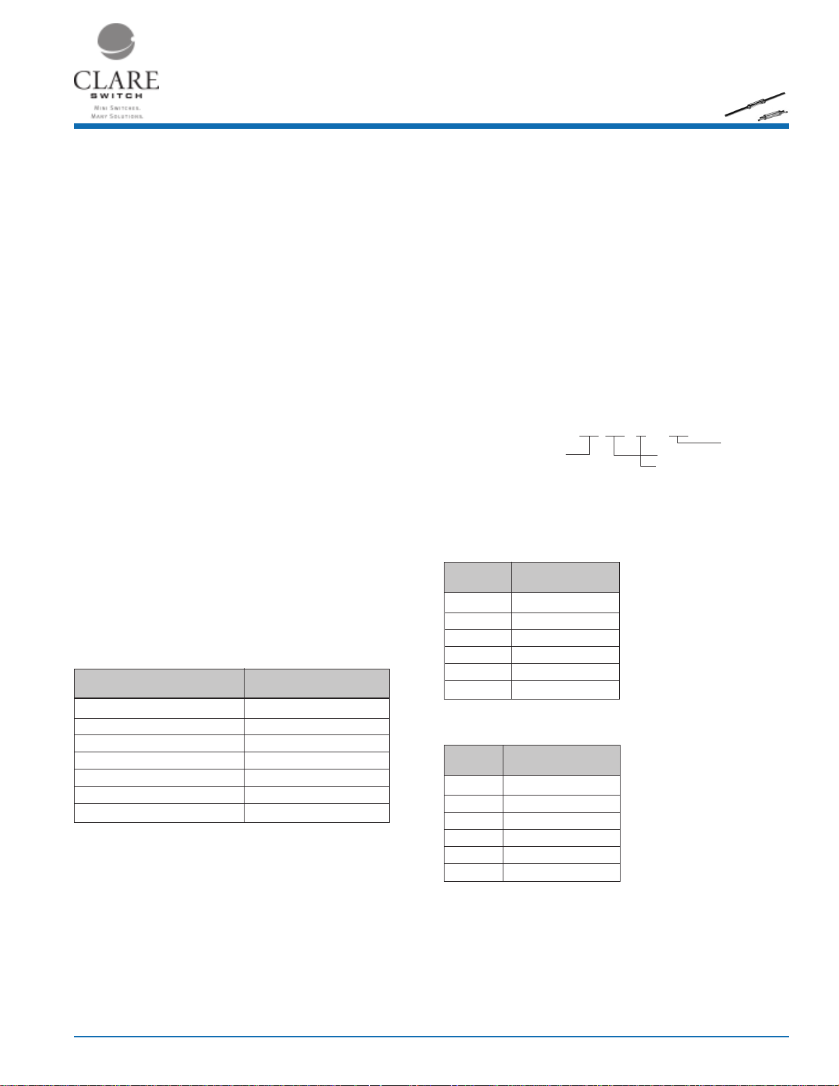
Standard Test Coil
The magnetic force (expressed in NI, AT or Ampere Turns) required to cause the reed switch contacts to
close is called the pull-in or operate value.
MN2
Part # Coil - 1
Coil definition NARM1 CTC01
Coil resistance 1200Ω
Number of turns 5,000
Wire size (nom. diameter) 0.0399mm (AWG 46)
Bobbin diameter (inside coil) 3.96mm
Winding length 10.4mm
(1)
Consult factory for test procedure.
The reed switch shall be placed in the test coil with the gap centered in the core of the coil winding.
Test leads and their clips must be non-magnetic.
The longitudinal axis of the test coil and the test switch shall be vertical.
Ordering Information
A complete part number is represented by the digits to the right. For example, MN2S1030 is a
MINI-DYAD™ with a minimum operate value of 10 and a maximum of 30. Refer to the switch
operating specification charts for available ranges. Special ranges are available upon request.
XX
1,2,3
X
Maximum Operate Value (NI)
Lead Configuration
1
Packaging
MN2S XX XX
Minimum Operate Value (NI)
Surface Mount Mini-Dyad
Refer to operating characteristics table for complete part number.
Mini-DYAD
TM
Part # Operate Range (NI)
MN2S1015 10 to 15
MN2S1020 10 to 20
MN2S1030 10 to 30
MN2S1520 15 to 20
MN2S1525 15 to 25
MN2S2025 20 to 25
Mini-DYAD
TM
Surface Mount
Part # Operate Range (NI)
MN2308 10 to 15
MN2288 10 to 20
MN2339 10 to 30
MN2285 15 to 20
MN2289 15 to 25
MN2286 20 to 25
1
Tolerance = ± 1.5NI
2
Full Blade Sensitivity
3
Surface Mount Switches are packaged 2,000 parts per reel
DS-MN2-R2
www.clare.com
1
Mini-Dyad
MN2
™
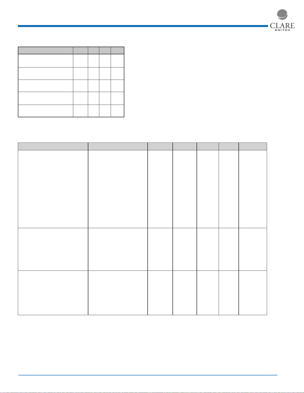
Ratings (@ 25˚ C)
Parameter Min Typ Max Units
Switching Voltage
MN2 - Mini-DYAD
Switching Current
MN2 - Mini-DYAD
Carry Current
MN2 - Mini-DYAD
™
™
™
- - 200 Volts
- - 0.5 Amps
- - 2 Amps
Absolute Maximum Ratings are stress ratings. Stresses
in excess of these ratings can cause permanent damage
to the device. Functional operation of the device at these
or any other conditions beyond those indicated in the
operational sections of this data sheet is not implied.
Exposure of the device to the absolute maximum ratings
for extended period may degrade the device and effect
its reliability.
Switching Frequency
MN2 - Mini-DYAD
™
- - 500 Hz
Contact Resistance
MN2 - Mini-DYAD
(See detailed specifications for more information.)
™
- -0 100 mΩ
Specifications
All parameters are at 25°C unless otherwise stated.
PARAMETER CONDITIONS SYMBOL MIN TYP MAX UNITS
Contact Ratings
Operate ampere turns range Full Blade Tolerance = ± 1.5NI AT 10 - 25 NI
Release ampere turns range Full Blade Tolerance = ± 1.5NI AT 5 - 25 NI
Switching Voltage Max DC/PeakAC Resistive V
Switching Current Max DC/PeakAC Resistive I
Carry Current Max DC/PeakAC Resistive I
L
L
C
Contact Rating Max DC/PeakAC Resistive - - - 10 VA
Life Expectancy 1V, 10mA Signal Level - - 1000 - x10
10V, 10mA Low Level - - 500 - -x10
50V, 100mA Telecom Load - - 2 - x10
100V, 100mA Rated Loads - - 2 - x10
Static Contact Resistance 50mV, 10mA
(1)
CR - 70 100 Ω
Contact Material - - Ru - -
Switch Specifications
Insulation Resistance
(2)
100V, 25°C, 40% RH IR 10
Capacitance Across Open Contacts - - 0.3 - pF
Dielectric Strength
Operate Time, At nominal coil voltage, T
(5)
Between Contacts - 250 300 - VDC/Peak AC
OP
including bounce 10Hz Square Wave
Release Time Zener-Diode Suppression
(3)
T
REL
Environmental Ratings
Storage Temperature T
Operating Temperature T
A
O
Soldering Temperature - - - +265 ˚C
Vibration Resistance 5Hz - 200Hz G - - 20 -Gs
1
Shock Resistance 11±1ms,
/2 Sine Wave S - - 50 Gs
Weight - - 0.12 - grams/unit
(1)
Contact resistance measured with 4 terminal method, 1.1" between test leads
(2)
>1012 Ω is available upon request
(3)
A 24V zener in series with a diode across the coil
(4)
Use caution not to exceed vibration resistance limits while ultrasonically cleaning. Contact CP Clare
Engineering for more details/ recommendations
(5)
15 ampere turn minimum
- - 200 VDC
- - 500 mAmps
- - 2.0 Amps
9
10
11
- Ω
- - 0.5 ms
- - 0.1 ms
-40 - +125 ˚C
-40 - +125 ˚C
6
Ops
6
Ops
6
Ops
6
Ops
2
www.clare.com
Rev. 2
 Loading...